coil CHRYSLER VOYAGER 2005 Manual PDF
[x] Cancel search | Manufacturer: CHRYSLER, Model Year: 2005, Model line: VOYAGER, Model: CHRYSLER VOYAGER 2005Pages: 2339, PDF Size: 59.69 MB
Page 2177 of 2339

(4) Install the glove box (Refer to 23 - BODY/IN-
STRUMENT PANEL/GLOVE BOX - INSTALLA-
TION).
(5) Reconnect the battery negative cable.
EVAPORATOR TEMPERATURE
SENSOR
DESCRIPTION
The evaporator temperature sensor used for the
manual and automatic temperature control systems
on RS models is installed on the top of the HVAC
housing behind the instrument panel and measures
the air temperature downstream of the evaporator
(Fig. 15). The sensor is an electrical thermistor in a
plastic housing that is inserted into the HVAC hous-
ing. Two terminals within the molded plastic connec-
tor receptacle on the sensor connect it to the vehicle
electrical system through a take out and connector of
the HVAC wire harness.
The evaporator temperature sensor used for the
manual and automatic temperature control systems
on RG models is installed on the top of the expansion
valve in the right rear corner of the engine compart-
ment and measures the temperature of the evapora-
tor coils (Fig. 16). The sensor has a small probe that
is inserted in a small well in the body of the expan-
sion valve that is filled with a special silicone-based
thermal grease. A small molded plastic push-in
retainer secures the sensor to a threaded hole in the
top surface of the expansion valve. Two terminals
within a molded plastic connector receptacle on thesensor connect it to the vehicle electrical system
through a take out and connector of the HVAC wire
harness.
Fig. 14 Blower Motor Resistor Block - Typical
1 - BLOWER MOTOR RESISTOR
2 - INSTRUMENT PANEL WIRE HARNESS
3 - SCREW (2)
4 - GLOVE BOX OPENING REINFORCEMENT
5 - BLOWER MOTOR PIGTAIL WIRE HARNESS
6 - HVAC HOUSING
Fig. 15 Evaporator Temperature Sensor - RS Models
1 - EVAPORATOR TEMPERATURE SENSOR
2 - HVAC HOUSING
3 - A/C EVAPORATOR
Fig. 16 Evaporator Temperature Sensor - RG Models
1 - EVAPORATOR TEMPERATURE SENSOR
2 - A/C EXPANSION VALVE
24 - 26 CONTROLS - FRONTRS
BLOWER MOTOR RESISTOR BLOCK (Continued)
Page 2187 of 2339
(6) Install the screw that secures the front of the
rear HVAC housing to the right quarter inner panel.
Tighten the screw to 11 N´m (97 in. lbs.).
(7) Install the screw that secures the back of the
rear HVAC housing to the right D-pillar. Tighten the
screw to 11 N´m (97 in. lbs.).
(8) Install the two screws that secure the top of
the quarter trim panel attaching bracket to the quar-
ter inner panel. Tighten the screws to 2 N´m (17 in.
lbs.).
(9) Reinstall the right quarter trim panel and
right D-pillar trim panel onto the quarter inner
panel (Refer to 23 - BODY/INTERIOR/QUARTER
TRIM PANEL - INSTALLATION).
(10) Reconnect the battery negative cable.
(11) Perform the heater-A/C control calibration
procedure (Refer to 24 - HEATING & AIR CONDI-
TIONING/CONTROLS - FRONT/A/C-HEATER CON-
TROL - STANDARD PROCEDURE - HEATER-A/C
CONTROL CALIBRATION).
BLOWER MOTOR RELAY
DESCRIPTION
The rear blower motor relay is a International
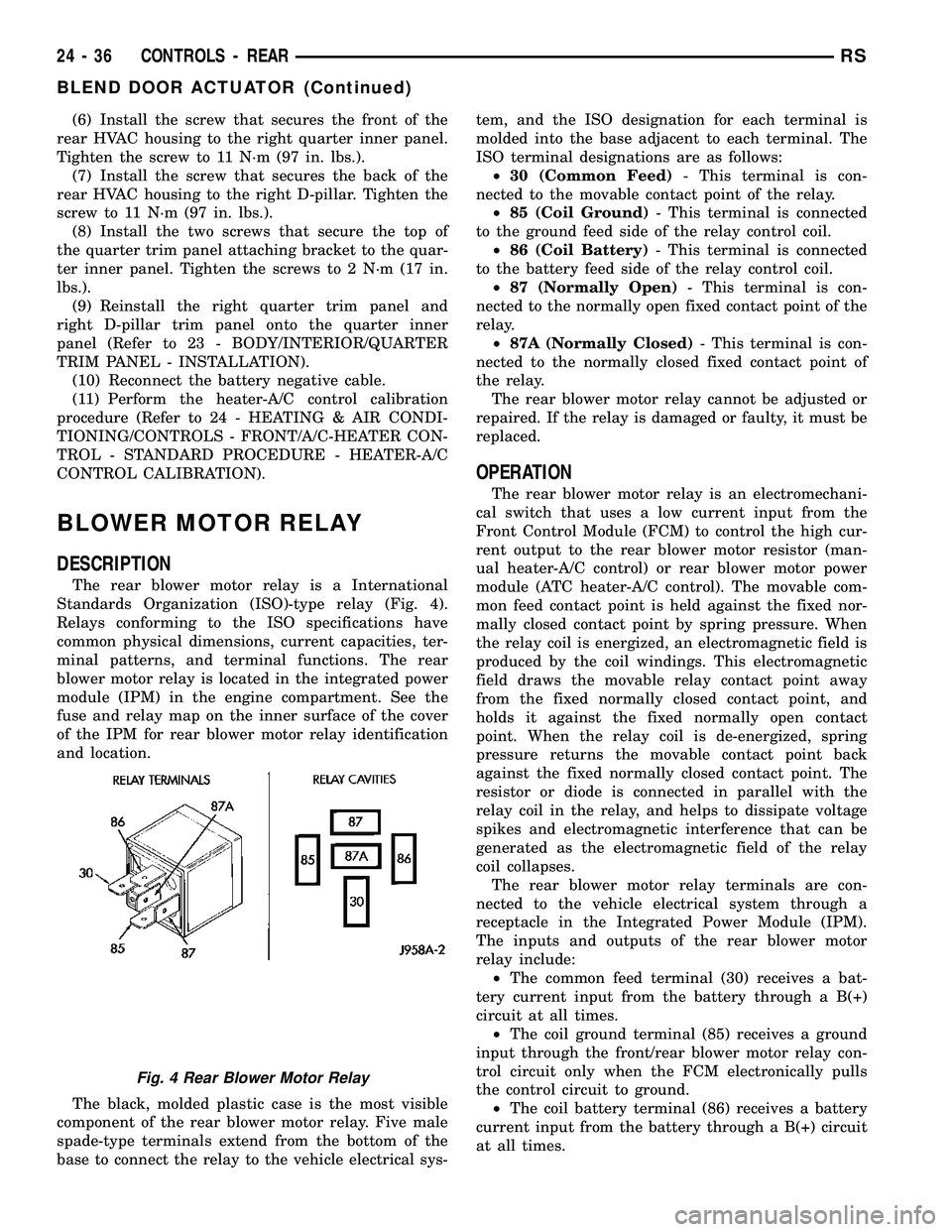
Standards Organization (ISO)-type relay (Fig. 4).
Relays conforming to the ISO specifications have
common physical dimensions, current capacities, ter-
minal patterns, and terminal functions. The rear
blower motor relay is located in the integrated power
module (IPM) in the engine compartment. See the
fuse and relay map on the inner surface of the cover
of the IPM for rear blower motor relay identification
and location.
The black, molded plastic case is the most visible
component of the rear blower motor relay. Five male
spade-type terminals extend from the bottom of the
base to connect the relay to the vehicle electrical sys-tem, and the ISO designation for each terminal is
molded into the base adjacent to each terminal. The
ISO terminal designations are as follows:
²30 (Common Feed)- This terminal is con-
nected to the movable contact point of the relay.
²85 (Coil Ground)- This terminal is connected
to the ground feed side of the relay control coil.
²86 (Coil Battery)- This terminal is connected
to the battery feed side of the relay control coil.
²87 (Normally Open)- This terminal is con-
nected to the normally open fixed contact point of the
relay.
²87A (Normally Closed)- This terminal is con-
nected to the normally closed fixed contact point of
the relay.
The rear blower motor relay cannot be adjusted or
repaired. If the relay is damaged or faulty, it must be
replaced.
OPERATION
The rear blower motor relay is an electromechani-
cal switch that uses a low current input from the
Front Control Module (FCM) to control the high cur-
rent output to the rear blower motor resistor (man-
ual heater-A/C control) or rear blower motor power
module (ATC heater-A/C control). The movable com-
mon feed contact point is held against the fixed nor-
mally closed contact point by spring pressure. When
the relay coil is energized, an electromagnetic field is
produced by the coil windings. This electromagnetic
field draws the movable relay contact point away
from the fixed normally closed contact point, and
holds it against the fixed normally open contact
point. When the relay coil is de-energized, spring
pressure returns the movable contact point back
against the fixed normally closed contact point. The
resistor or diode is connected in parallel with the
relay coil in the relay, and helps to dissipate voltage
spikes and electromagnetic interference that can be
generated as the electromagnetic field of the relay
coil collapses.
The rear blower motor relay terminals are con-
nected to the vehicle electrical system through a
receptacle in the Integrated Power Module (IPM).
The inputs and outputs of the rear blower motor
relay include:
²The common feed terminal (30) receives a bat-
tery current input from the battery through a B(+)
circuit at all times.
²The coil ground terminal (85) receives a ground
input through the front/rear blower motor relay con-
trol circuit only when the FCM electronically pulls
the control circuit to ground.
²The coil battery terminal (86) receives a battery
current input from the battery through a B(+) circuit
at all times.
Fig. 4 Rear Blower Motor Relay
24 - 36 CONTROLS - REARRS
BLEND DOOR ACTUATOR (Continued)
Page 2188 of 2339
²The normally open terminal (87) provides a bat-
tery current output to the blower motor resistor
(manual heater-A/C control) or blower power module
(ATC heater-A/C control) through a fuse in the IPM
on the fused rear blower motor relay output circuit
only when the blower motor relay coil is energized.
²The normally closed terminal (87A) is not con-
nected to any circuit in this application, but provides
a battery current output only when the rear blower
motor relay coil is de-energized.
Refer to the appropriate wiring information for
diagnosis and testing of the micro-relay and for com-
plete HVAC wiring diagrams.
REMOVAL
(1) Disconnect and isolate the negative battery
cable.
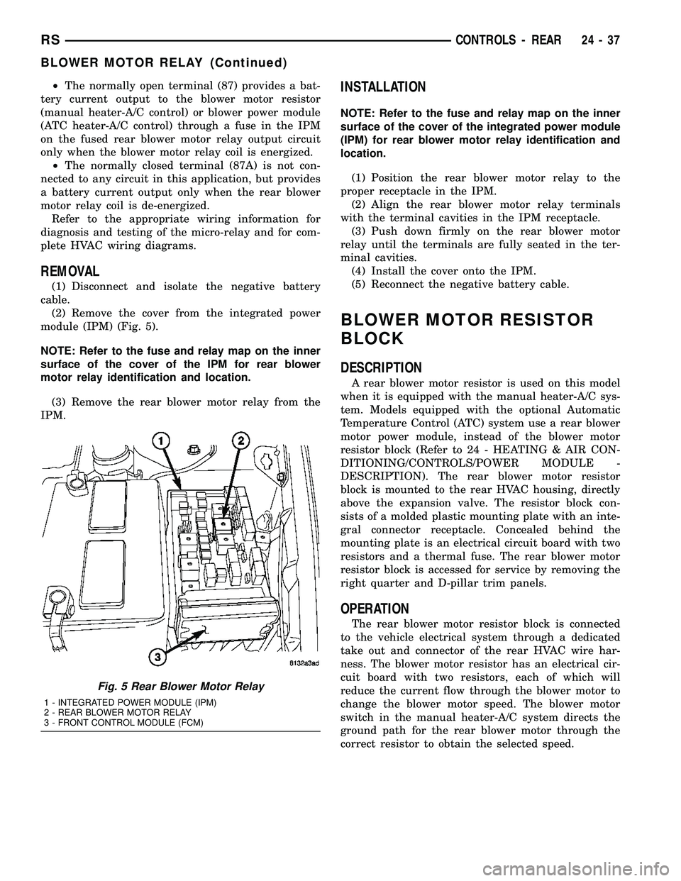
(2) Remove the cover from the integrated power
module (IPM) (Fig. 5).
NOTE: Refer to the fuse and relay map on the inner
surface of the cover of the IPM for rear blower
motor relay identification and location.
(3) Remove the rear blower motor relay from the
IPM.
INSTALLATION
NOTE: Refer to the fuse and relay map on the inner
surface of the cover of the integrated power module
(IPM) for rear blower motor relay identification and
location.
(1) Position the rear blower motor relay to the
proper receptacle in the IPM.
(2) Align the rear blower motor relay terminals
with the terminal cavities in the IPM receptacle.
(3) Push down firmly on the rear blower motor
relay until the terminals are fully seated in the ter-
minal cavities.
(4) Install the cover onto the IPM.
(5) Reconnect the negative battery cable.
BLOWER MOTOR RESISTOR
BLOCK
DESCRIPTION
A rear blower motor resistor is used on this model
when it is equipped with the manual heater-A/C sys-
tem. Models equipped with the optional Automatic
Temperature Control (ATC) system use a rear blower
motor power module, instead of the blower motor
resistor block (Refer to 24 - HEATING & AIR CON-
DITIONING/CONTROLS/POWER MODULE -
DESCRIPTION). The rear blower motor resistor
block is mounted to the rear HVAC housing, directly
above the expansion valve. The resistor block con-
sists of a molded plastic mounting plate with an inte-
gral connector receptacle. Concealed behind the
mounting plate is an electrical circuit board with two
resistors and a thermal fuse. The rear blower motor
resistor block is accessed for service by removing the
right quarter and D-pillar trim panels.
OPERATION
The rear blower motor resistor block is connected
to the vehicle electrical system through a dedicated
take out and connector of the rear HVAC wire har-
ness. The blower motor resistor has an electrical cir-
cuit board with two resistors, each of which will
reduce the current flow through the blower motor to
change the blower motor speed. The blower motor
switch in the manual heater-A/C system directs the
ground path for the rear blower motor through the
correct resistor to obtain the selected speed.
Fig. 5 Rear Blower Motor Relay
1 - INTEGRATED POWER MODULE (IPM)
2 - REAR BLOWER MOTOR RELAY
3 - FRONT CONTROL MODULE (FCM)
RSCONTROLS - REAR24-37
BLOWER MOTOR RELAY (Continued)
Page 2223 of 2339

(4) Open both the suction and discharge valves,
then open the charge valve to allow the heated
refrigerant to flow into the system.
(5) When the transfer of refrigerant has stopped,
close both the suction and discharge valves.
(6) If all of the refrigerant charge did not transfer
from the dispensing device, open all of the windows
in the vehicle and set the heater-air conditioner con-
trols so that the compressor is engaged and the
blower motor is operating at its lowest speed setting.
Run the engine at a steady high idle (about 1400
rpm). If the compressor will not engage, test the com-
pressor clutch control circuit and repair as required.
(7) Open the suction valve to allow the remaining
refrigerant to transfer to the refrigerant system.
WARNING: TAKE CARE NOT TO OPEN THE DIS-
CHARGE (HIGH PRESSURE) VALVE AT THIS TIME.
(8) Close the suction valve and test the system
performance. (Refer to 24 - HEATING & AIR CON-
DITIONING - STANDARD PROCEDURE - A/C PER-
FORMANCE TEST).
(9) Disconnect the charging station and manifold
gauge set from the refrigerant system service ports.
(10) Reinstall the caps onto the refrigerant system
service ports.
(11) Run the HVAC Control Cooldown test to ver-
ify proper operation(Refer to 24 - HEATING & AIR
CONDITIONING - DIAGNOSIS AND TESTING).
A/C COMPRESSOR
DESCRIPTION
A/C COMPRESSOR
Vehicles equipped with the 2.4L gasoline, 2.5L die-
sel, 2.8L diesel and 3.3L gasoline engines with the
front heating-A/C system only, use the Denso 10S17
A/C compressor. Vehicles equipped with the 3.3L and
the 3.8L gasoline engines with the optional rear heat-
ing-A/C system use the Denso 10S20 A/C compressor.
Both A/C compressors include an integral high pres-
sure relief valve. The A/C compressor is secured to a
mounting bracket on the 2.4L gasoline engine and
directly to the cylinder block on the 2.5L diesel, 2.8L
diesel, 3.3L gasoline and 3.8L gasoline engines.
HIGH PRESSURE RELIEF VALVE
A high pressure relief valve is located on the rear
of the A/C compressor. This mechanical valve is
designed to vent refrigerant from the A/C system to
protect against damage to the compressor and other
system components, caused by condenser air flow
restriction or an overcharge of refrigerant.
OPERATION
A/C COMPRESSOR
The A/C compressor is driven by the engine
through an electric clutch, drive pulley and belt
arrangement. The compressor is lubricated by refrig-
erant oil that is circulated throughout the refrigerant
system with the refrigerant.
The compressor draws in low-pressure refrigerant
vapor from the evaporator through its suction port. It
then compresses the refrigerant into a high-pressure,
high-temperature refrigerant vapor. The compressor
pumps the high-pressure refrigerant vapor to the
condenser through the compressor discharge port.
The compressor cannot be repaired. If faulty or
damaged, the entire compressor assembly must be
replaced. The compressor clutch, pulley and clutch
coil are available for service.
HIGH PRESSURE RELIEF VALVE
The high pressure relief valve vents the system
when a discharge pressure of 3445 to 4135 kPa (500
to 600 psi) or above is reached. The valve closes
when a minimum discharge pressure of 2756 kPa
(400 psi) is reached.
The high pressure relief valve vents only enough
refrigerant to reduce the system pressure, and then
re-seats itself. The majority of the refrigerant is con-
served in the system. If the valve vents refrigerant, it
does not mean that the valve is faulty.
The high pressure relief valve is a factory-cali-
brated unit. The valve cannot be adjusted or
repaired, and must not be removed or otherwise dis-
turbed. The valve is only serviced as a part of the
compressor assembly.
DIAGNOSIS AND TESTING
A/C COMPRESSOR NOISE DIAGNOSIS
Excessive noise while the air conditioning compres-
sor is operating can be caused by loose compressor
mounts, a loose compressor clutch, or high operating
pressures in the refrigerant system. Verify compres-
sor drive belt condition, proper compressor mounting,
correct refrigerant charge level, and compressor head
pressure before compressor repair is performed.
With the close tolerances within the compressor, it
is possible to experience a temporary lockup. The
longer the compressor is inactive, the more likely the
condition is to occur. This condition is the result of
normal refrigerant migration within the refrigerant
system caused by ambient temperature changes. The
refrigerant migration may wash the refrigerant oil
out of the compressor.
24 - 72 PLUMBING - FRONTRS
PLUMBING - FRONT (Continued)
Page 2224 of 2339
NOTE: Prior to a vehicle being removed from ser-
vice or stored for more than two weeks, the com-
pressor should be operated to ensure adequate
refrigerant oil distribution throughout the system
components. Turn on the air conditioner for a min-
imum of five minutes with outside air and the high-
est blower speed selected.
BELT NOISE
If the compressor drive belt slips at initial start-up,
it does not necessarily mean the compressor has
failed. The following procedure can be used to iden-
tify a compressor drive belt noise problem.
A. Start the vehicle and run at idle.
B. Turn the air conditioner On and listen for belt
squeal.
C. If belt squeal is heard, turn the air conditioner
Off immediately.
If the belt squeal stops when the air conditioner is
turned Off, perform the following repair procedures.
(1) Using an appropriate sized oil filter wrench or
a strap wrench, grasp the outer diameter of the com-
pressor clutch hub. While facing the compressor,
rotate the hub clockwise, then counterclockwise. If
the hub rotates, proceed to the next step. If the hub
will not rotate, the compressor is internally damaged,
and must be replaced.
(2) Turn the hub clockwise five complete revolu-
tions and remove the tool.
(3) Start the vehicle and run at idle.
(4) Turn the air conditioner On. Observe the com-
pressor and the system for normal operation, noting
cooling performance and noise levels. Operate for five
minutes before turning the air conditioner Off. If
acceptable cooling performance is observed during
compressor operation, the compressor does not need
to be replaced.
(5) Inspect the drive belt for wear, damage, and
proper tension. (Refer to 7 - COOLING/ACCESSORY
DRIVE/DRIVE BELTS - DIAGNOSIS AND TEST-
ING).
REMOVAL
A/C COMPRESSOR
WARNING: REFER TO THE APPLICABLE WARN-
INGS AND CAUTIONS FOR THIS SYSTEM BEFORE
PERFORMING THE FOLLOWING OPERATION (Refer
to 24 - HEATING & AIR CONDITIONING/PLUMBING -
FRONT - WARNING - A/C PLUMBING) and (Refer to
24 - HEATING & AIR CONDITIONING/PLUMBING -
FRONT - CAUTION - A/C PLUMBING).(1) Recover the refrigerant from the refrigerant
system (Refer to 24 - HEATING & AIR CONDITION-
ING/PLUMBING - FRONT/REFRIGERANT - STAN-
DARD PROCEDURE - REFRIGERANT SYSTEM
RECOVERY).
(2) Disconnect and isolate the negative battery
cable.
(3) Remove the nuts that secure the A/C suction
line and the A/C discharge line to the A/C compres-
sor.
(4) Disconnect the A/C suction line and the A/C
discharge line from the A/C compressor.
(5) Remove the O-ring seal and gasket from the
suction and discharge line fittings and discard.
(6) Install plugs in, or tape over the opened suc-
tion and discharge fittings and the compressor ports.
(7) Raise and support the vehicle.
(8) Remove the accessory drive belt (Refer to 7 -
COOLING/ACCESSORY DRIVE/DRIVE BELTS -
REMOVAL).
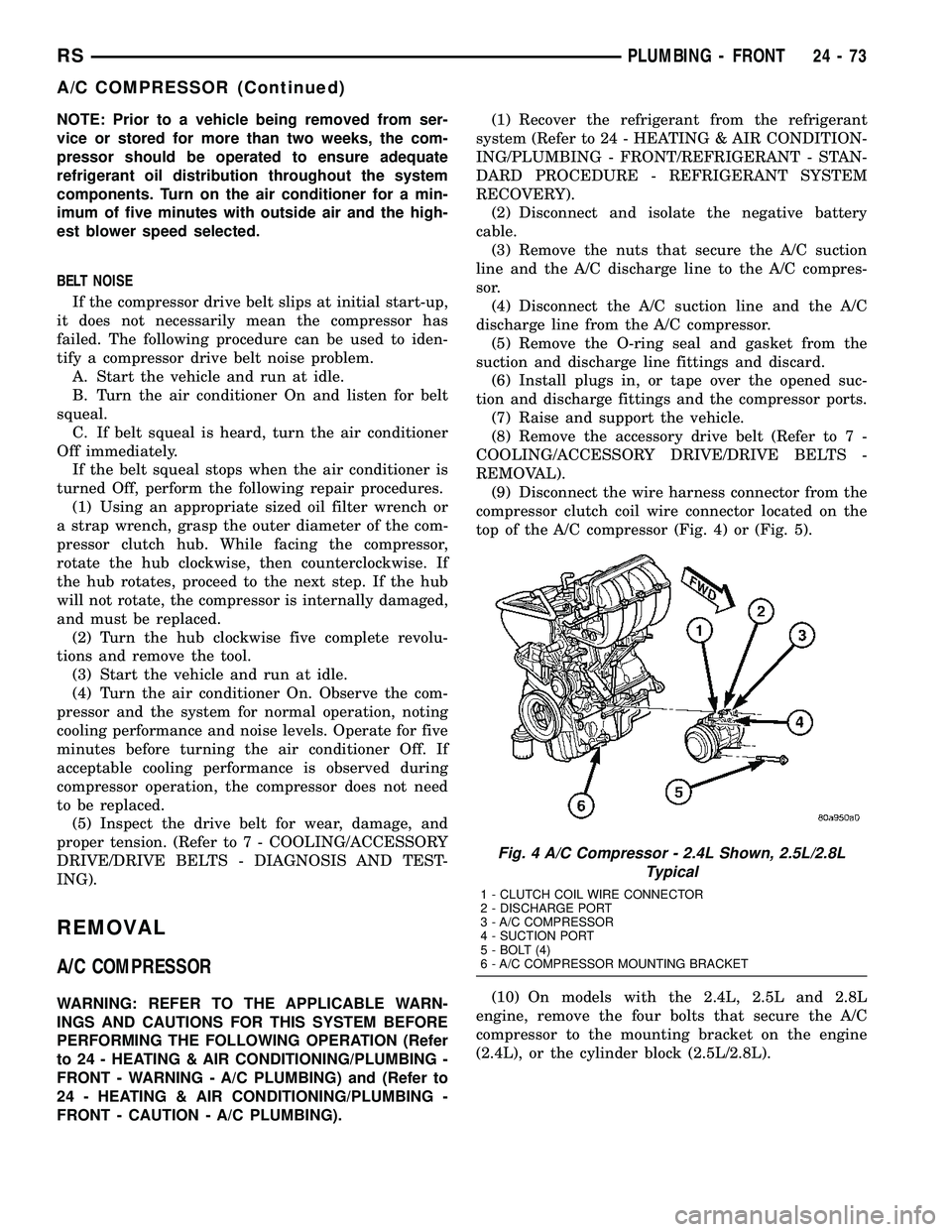
(9) Disconnect the wire harness connector from the
compressor clutch coil wire connector located on the
top of the A/C compressor (Fig. 4) or (Fig. 5).
(10) On models with the 2.4L, 2.5L and 2.8L
engine, remove the four bolts that secure the A/C
compressor to the mounting bracket on the engine
(2.4L), or the cylinder block (2.5L/2.8L).
Fig. 4 A/C Compressor - 2.4L Shown, 2.5L/2.8L
Typical
1 - CLUTCH COIL WIRE CONNECTOR
2 - DISCHARGE PORT
3 - A/C COMPRESSOR
4 - SUCTION PORT
5 - BOLT (4)
6 - A/C COMPRESSOR MOUNTING BRACKET
RSPLUMBING - FRONT24-73
A/C COMPRESSOR (Continued)
Page 2225 of 2339
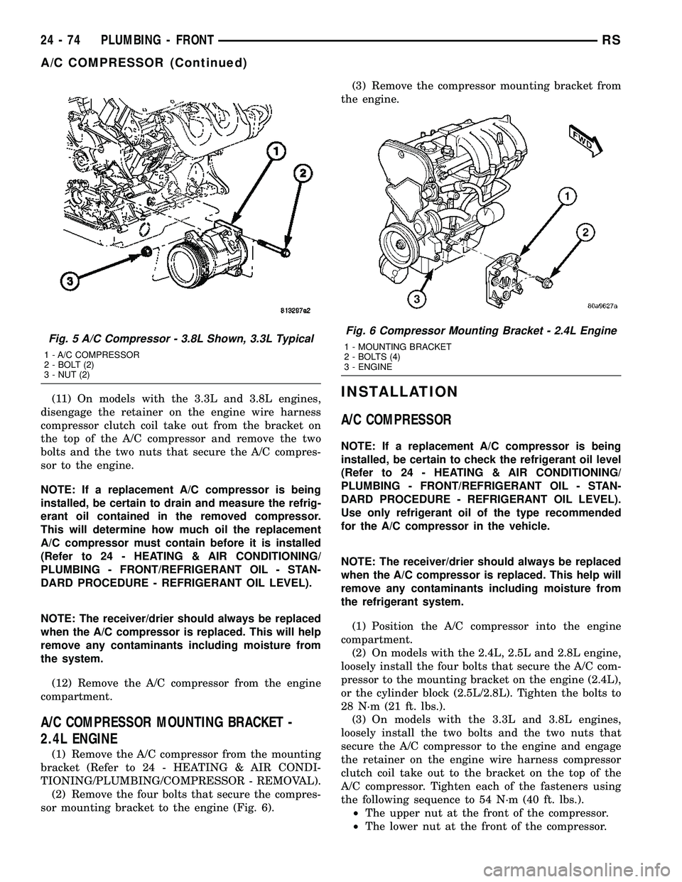
(11) On models with the 3.3L and 3.8L engines,
disengage the retainer on the engine wire harness
compressor clutch coil take out from the bracket on
the top of the A/C compressor and remove the two
bolts and the two nuts that secure the A/C compres-
sor to the engine.
NOTE: If a replacement A/C compressor is being
installed, be certain to drain and measure the refrig-
erant oil contained in the removed compressor.
This will determine how much oil the replacement
A/C compressor must contain before it is installed
(Refer to 24 - HEATING & AIR CONDITIONING/
PLUMBING - FRONT/REFRIGERANT OIL - STAN-
DARD PROCEDURE - REFRIGERANT OIL LEVEL).
NOTE: The receiver/drier should always be replaced
when the A/C compressor is replaced. This will help
remove any contaminants including moisture from
the system.
(12) Remove the A/C compressor from the engine
compartment.
A/C COMPRESSOR MOUNTING BRACKET -
2.4L ENGINE
(1) Remove the A/C compressor from the mounting
bracket (Refer to 24 - HEATING & AIR CONDI-
TIONING/PLUMBING/COMPRESSOR - REMOVAL).
(2) Remove the four bolts that secure the compres-
sor mounting bracket to the engine (Fig. 6).(3) Remove the compressor mounting bracket from
the engine.
INSTALLATION
A/C COMPRESSOR
NOTE: If a replacement A/C compressor is being
installed, be certain to check the refrigerant oil level
(Refer to 24 - HEATING & AIR CONDITIONING/
PLUMBING - FRONT/REFRIGERANT OIL - STAN-
DARD PROCEDURE - REFRIGERANT OIL LEVEL).
Use only refrigerant oil of the type recommended
for the A/C compressor in the vehicle.
NOTE: The receiver/drier should always be replaced
when the A/C compressor is replaced. This help will
remove any contaminants including moisture from
the refrigerant system.
(1) Position the A/C compressor into the engine
compartment.
(2) On models with the 2.4L, 2.5L and 2.8L engine,
loosely install the four bolts that secure the A/C com-
pressor to the mounting bracket on the engine (2.4L),
or the cylinder block (2.5L/2.8L). Tighten the bolts to
28 N´m (21 ft. lbs.).
(3) On models with the 3.3L and 3.8L engines,
loosely install the two bolts and the two nuts that
secure the A/C compressor to the engine and engage
the retainer on the engine wire harness compressor
clutch coil take out to the bracket on the top of the
A/C compressor. Tighten each of the fasteners using
the following sequence to 54 N´m (40 ft. lbs.).
²The upper nut at the front of the compressor.
²The lower nut at the front of the compressor.
Fig. 5 A/C Compressor - 3.8L Shown, 3.3L Typical
1 - A/C COMPRESSOR
2 - BOLT (2)
3 - NUT (2)
Fig. 6 Compressor Mounting Bracket - 2.4L Engine
1 - MOUNTING BRACKET
2 - BOLTS (4)
3 - ENGINE
24 - 74 PLUMBING - FRONTRS
A/C COMPRESSOR (Continued)
Page 2226 of 2339
²The upper bolt at the rear of the compressor.
²The lower bolt at the rear of the compressor.
(4) Connect the wire harness connector to the com-
pressor clutch coil wire connector.
(5) Install the accessory drive belt (Refer to 7 -
COOLING/ACCESSORY DRIVE/DRIVE BELTS -
INSTALLATION).
(6) Lower the vehicle.
(7) Remove the tape or plugs from the suction and
discharge line fittings and the compressor ports.
(8) Lubricate new rubber O-ring seals with clean
refrigerant oil and install them and a new gasket
onto the suction and discharge line fittings.
(9) Connect the A/C suction line and the A/C dis-
charge line to the A/C compressor.
(10) Install the nut that secures the A/C suction
line and the A/C discharge line to the A/C compres-
sor. Tighten the nuts to 23 N´m (17 ft. lbs.).
(11) Reconnect the negative battery cable.
(12) Evacuate the refrigerant system (Refer to 24 -
HEATING & AIR CONDITIONING/PLUMBING -
FRONT/REFRIGERANT - STANDARD PROCE-
DURE - REFRIGERANT SYSTEM EVACUATE).
(13) Charge the refrigerant system (Refer to 24 -
HEATING & AIR CONDITIONING/PLUMBING -
FRONT/REFRIGERANT - STANDARD PROCE-
DURE - REFRIGERANT SYSTEM CHARGE).
A/C COMPRESSOR MOUNTING BRACKET -
2.4L ENGINE
(1) Position the compressor mounting bracket onto
the engine.
(2) Install the four bolts that secure the compres-
sor mounting bracket to the engine. Tighten the bolts
to 54 N´m (40 ft. lbs.).
(3) Reinstall the A/C compressor onto the mount-
ing bracket (Refer to 24 - HEATING & AIR CONDI-
TIONING/PLUMBING/COMPRESSOR -
INSTALLATION).
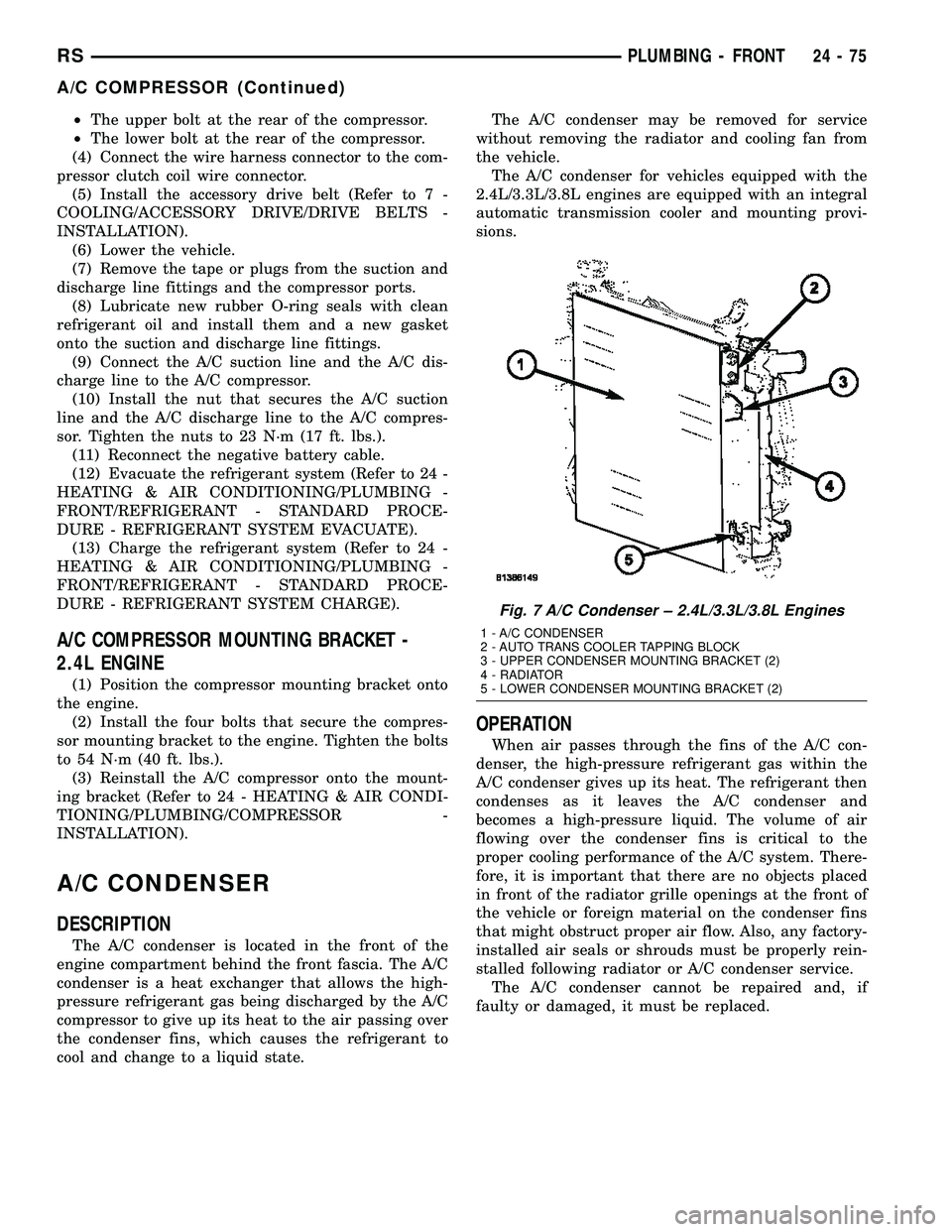
A/C CONDENSER
DESCRIPTION
The A/C condenser is located in the front of the
engine compartment behind the front fascia. The A/C
condenser is a heat exchanger that allows the high-
pressure refrigerant gas being discharged by the A/C
compressor to give up its heat to the air passing over
the condenser fins, which causes the refrigerant to
cool and change to a liquid state.The A/C condenser may be removed for service
without removing the radiator and cooling fan from
the vehicle.
The A/C condenser for vehicles equipped with the
2.4L/3.3L/3.8L engines are equipped with an integral
automatic transmission cooler and mounting provi-
sions.
OPERATION
When air passes through the fins of the A/C con-
denser, the high-pressure refrigerant gas within the
A/C condenser gives up its heat. The refrigerant then
condenses as it leaves the A/C condenser and
becomes a high-pressure liquid. The volume of air
flowing over the condenser fins is critical to the
proper cooling performance of the A/C system. There-
fore, it is important that there are no objects placed
in front of the radiator grille openings at the front of
the vehicle or foreign material on the condenser fins
that might obstruct proper air flow. Also, any factory-
installed air seals or shrouds must be properly rein-
stalled following radiator or A/C condenser service.
The A/C condenser cannot be repaired and, if
faulty or damaged, it must be replaced.
Fig. 7 A/C Condenser ± 2.4L/3.3L/3.8L Engines
1 - A/C CONDENSER
2 - AUTO TRANS COOLER TAPPING BLOCK
3 - UPPER CONDENSER MOUNTING BRACKET (2)
4 - RADIATOR
5 - LOWER CONDENSER MOUNTING BRACKET (2)
RSPLUMBING - FRONT24-75
A/C COMPRESSOR (Continued)
Page 2231 of 2339
INSTALLATION
(1) Position the A/C discharge line into the engine
compartment.
(2) Remove the tape or plugs from the compressor
discharge port and the discharge line fitting.
(3) Lubricate a new rubber O-ring seal with clean
refrigerant oil and install it and a new gasket onto
the discharge line fitting.
(4) Install the A/C discharge line to the A/C com-
pressor.(5) Install the nut that secures the A/C discharge
line to the A/C compressor. Tighten the nut to 23
N´m (17 ft. lbs.).
(6) Remove the tape or plugs from the condenser
inlet port and the discharge line fitting.
(7) Lubricate a new rubber O-ring seal with clean
refrigerant oil and install it and a new gasket onto
the discharge line fitting.
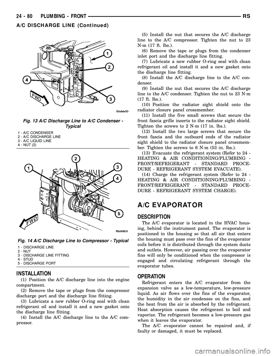
(8) Install the A/C discharge line to the A/C con-
denser.
(9) Install the nut that secures the A/C discharge
line to the A/C condenser. Tighten the nut to 23 N´m
(17 ft. lbs.).
(10) Position the radiator sight shield onto the
radiator closure panel crossmember.
(11) Install the five small screws that secure the
front fascia grille inserts to the radiator sight shield.
Tighten the screws to 2 N´m (17 in. lbs.).
(12) Install the two large screws that secure the
front fascia and the outboard ends of the radiator
sight shield to the radiator closure panel crossmem-
ber. Tighten the screws to 6 N´m (53 in. lbs.).
(13) Evacuate the refrigerant system (Refer to 24 -
HEATING & AIR CONDITIONING/PLUMBING -
FRONT/REFRIGERANT - STANDARD PROCE-
DURE - REFRIGERANT SYSTEM EVACUATE).
(14) Charge the refrigerant system (Refer to 24 -
HEATING & AIR CONDITIONING/PLUMBING -
FRONT/REFRIGERANT - STANDARD PROCE-
DURE - REFRIGERANT SYSTEM CHARGE).
A/C EVAPORATOR
DESCRIPTION
The A/C evaporator is located in the HVAC hous-
ing, behind the instrument panel. The evaporator is
positioned in the housing so that all air that enters
the housing must pass over the fins of the evaporator
coils before it is distributed through the system ducts
and outlets. However, air passing over the evaporator
fins will only be conditioned when the compressor is
engaged and circulating refrigerant through the
evaporator tubes.
OPERATION
Refrigerant enters the A/C evaporator from the
expansion valve as a low-temperature, low-pressure
liquid. As air flows over the fins of the evaporator,
the humidity in the air condenses on the fins, and
the heat from the air is absorbed by the refrigerant.
Heat absorption causes the refrigerant to boil and
vaporize. The refrigerant becomes a low-pressure gas
when it leaves the evaporator.
The A/C evaporator cannot be repaired and, if
faulty or damaged, it must be replaced.
Fig. 13 A/C Discharge Line to A/C Condenser -
Typical
1 - A/C CONDENSER
2 - A/C DISCHARGE LINE
3 - A/C LIQUID LINE
4 - NUT (2)
Fig. 14 A/C Discharge Line to Compressor - Typical
1 - DISCHARGE LINE
2 - NUT
3 - DISCHARGE LINE FITTING
4 - STUD
5 - DISCHARGE PORT
24 - 80 PLUMBING - FRONTRS
A/C DISCHARGE LINE (Continued)
Page 2232 of 2339
REMOVAL
WARNING: ON VEHICLES EQUIPPED WITH AIR-
BAGS, DISABLE THE AIRBAG SYSTEM BEFORE
ATTEMPTING ANY STEERING WHEEL, STEERING
COLUMN, OR INSTRUMENT PANEL COMPONENT
DIAGNOSIS OR SERVICE. DISCONNECT AND ISO-
LATE THE BATTERY NEGATIVE (GROUND) CABLE,
THEN WAIT TWO MINUTES FOR THE AIRBAG SYS-
TEM CAPACITOR TO DISCHARGE BEFORE PER-
FORMING FURTHER DIAGNOSIS OR SERVICE. THIS
IS THE ONLY SURE WAY TO DISABLE THE AIRBAG
SYSTEM. FAILURE TO TAKE THE PROPER PRE-
CAUTIONS COULD RESULT IN ACCIDENTAL AIR-
BAG DEPLOYMENT AND POSSIBLE PERSONAL
INJURY.
(1) Remove the HVAC housing (Refer to 24 -
HEATING & AIR CONDITIONING/DISTRIBUTION/
HVAC HOUSING - REMOVAL).
(2) Disassemble the HVAC housing to access the
evaporator (Refer to 24 - HEATING & AIR CONDI-
TIONING/DISTRIBUTION/HVAC HOUSING - DIS-
ASSEMBLY).
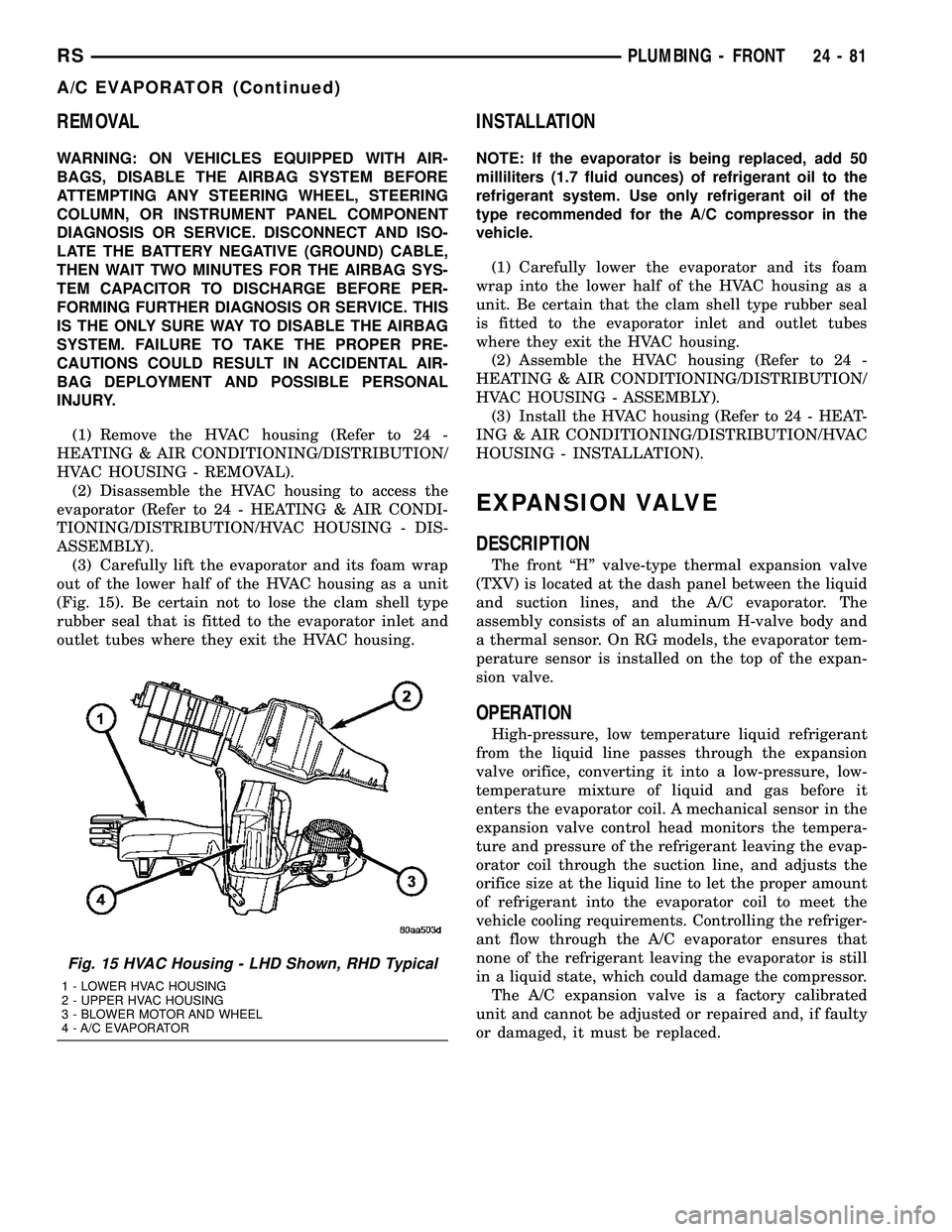
(3) Carefully lift the evaporator and its foam wrap
out of the lower half of the HVAC housing as a unit
(Fig. 15). Be certain not to lose the clam shell type
rubber seal that is fitted to the evaporator inlet and
outlet tubes where they exit the HVAC housing.
INSTALLATION
NOTE: If the evaporator is being replaced, add 50
milliliters (1.7 fluid ounces) of refrigerant oil to the
refrigerant system. Use only refrigerant oil of the
type recommended for the A/C compressor in the
vehicle.
(1) Carefully lower the evaporator and its foam
wrap into the lower half of the HVAC housing as a
unit. Be certain that the clam shell type rubber seal
is fitted to the evaporator inlet and outlet tubes
where they exit the HVAC housing.
(2) Assemble the HVAC housing (Refer to 24 -
HEATING & AIR CONDITIONING/DISTRIBUTION/
HVAC HOUSING - ASSEMBLY).
(3) Install the HVAC housing (Refer to 24 - HEAT-
ING & AIR CONDITIONING/DISTRIBUTION/HVAC
HOUSING - INSTALLATION).
EXPANSION VALVE
DESCRIPTION
The front ªHº valve-type thermal expansion valve
(TXV) is located at the dash panel between the liquid
and suction lines, and the A/C evaporator. The
assembly consists of an aluminum H-valve body and
a thermal sensor. On RG models, the evaporator tem-
perature sensor is installed on the top of the expan-
sion valve.
OPERATION
High-pressure, low temperature liquid refrigerant
from the liquid line passes through the expansion
valve orifice, converting it into a low-pressure, low-
temperature mixture of liquid and gas before it
enters the evaporator coil. A mechanical sensor in the
expansion valve control head monitors the tempera-
ture and pressure of the refrigerant leaving the evap-
orator coil through the suction line, and adjusts the
orifice size at the liquid line to let the proper amount
of refrigerant into the evaporator coil to meet the
vehicle cooling requirements. Controlling the refriger-
ant flow through the A/C evaporator ensures that
none of the refrigerant leaving the evaporator is still
in a liquid state, which could damage the compressor.
The A/C expansion valve is a factory calibrated
unit and cannot be adjusted or repaired and, if faulty
or damaged, it must be replaced.
Fig. 15 HVAC Housing - LHD Shown, RHD Typical
1 - LOWER HVAC HOUSING
2 - UPPER HVAC HOUSING
3 - BLOWER MOTOR AND WHEEL
4 - A/C EVAPORATOR
RSPLUMBING - FRONT24-81
A/C EVAPORATOR (Continued)
Page 2249 of 2339

PLUMBING - REAR
TABLE OF CONTENTS
page page
A/C EVAPORATOR
DESCRIPTION.........................98
OPERATION...........................98
REMOVAL
REAR A/C EVAPORATOR...............98
REAR A/C EVAPORATOR LINE
EXTENSION.........................99
INSTALLATION
REAR A/C EVAPORATOR..............100
REAR A/C EVAPORATOR LINE
EXTENSION........................100
A/C EXPANSION VALVE
DESCRIPTION........................100
OPERATION..........................100
DIAGNOSIS AND TESTING
REAR A/C EXPANSION VALVE..........101
REMOVAL............................101
INSTALLATION........................101
HEATER CORE
DESCRIPTION........................102
OPERATION..........................102
STANDARD PROCEDURE
REAR HEATER CORE FILLING..........102REMOVAL............................103
INSTALLATION........................104
HEATER HOSES
REMOVAL............................104
INSTALLATION........................105
LIQUID LINE
REMOVAL............................105
INSTALLATION........................106
SUCTION LINE
REMOVAL............................106
INSTALLATION........................107
UNDERBODY LINES
DESCRIPTION........................108
OPERATION..........................108
REMOVAL
UNDERBODY HEATER TUBES..........109
UNDERBODY REFRIGERANT LINES......110
INSTALLATION
UNDERBODY HEATER TUBES..........112
UNDERBODY REFRIGERANT LINES......112
A/C EVAPORATOR
DESCRIPTION
The rear A/C evaporator is located in the rear
HVAC housing, behind the right rear wheel house.
The evaporator is positioned in the rear housing so
that all air that enters the housing must pass over
the fins of the evaporator coils before it is distributed
through the system ducts and outlets. However, air
passing over the evaporator fins will only be condi-
tioned when the compressor is engaged and circulat-
ing refrigerant through the evaporator tubes. The
rear HVAC housing must be removed from the vehi-
cle to access the A/C evaporator for service.
OPERATION
Refrigerant enters the rear evaporator from the
rear expansion valve as a low-temperature, low-pres-
sure liquid. As air flows over the fins of the evapora-
tor, the humidity in the air condenses on the fins,
and the heat from the air is absorbed by the refrig-
erant. Heat absorption causes the refrigerant to boil
and vaporize. The refrigerant becomes a low-pressure
gas when it leaves the evaporator.
REMOVAL
REAR A/C EVAPORATOR
WARNING: REFER TO THE APPLICABLE WARN-
INGS AND CAUTIONS FOR THIS SYSTEM BEFORE
PERFORMING THE FOLLOWING OPERATION (Refer
to 24 - HEATING & AIR CONDITIONING/PLUMBING -
FRONT - WARNING - A/C PLUMBING), (Refer to 24 -
HEATING & AIR CONDITIONING/PLUMBING -
FRONT - CAUTION - A/C PLUMBING), and (Refer to
24 - HEATING & AIR CONDITIONING/PLUMBING -
FRONT - WARNING - HEATER PLUMBING).
(1) Remove the rear HVAC housing from the vehi-
cle (Refer to 24 - HEATING & AIR CONDITIONING/
DISTRIBUTION/HVAC HOUSING - REMOVAL).
(2) Remove the rear evaporator line extension from
the expansion valve (Refer to 24 - HEATING & AIR
CONDITIONING/PLUMBING - REAR/EVAPORA-
TOR - REMOVAL - EVAPORATOR LINE EXTEN-
SION).
(3) Remove the rear expansion valve from the rear
evaporator (Refer to 24 - HEATING & AIR CONDI-
24 - 98 PLUMBING - REARRS