ipm CHRYSLER VOYAGER 2005 Manual Online
[x] Cancel search | Manufacturer: CHRYSLER, Model Year: 2005, Model line: VOYAGER, Model: CHRYSLER VOYAGER 2005Pages: 2339, PDF Size: 59.69 MB
Page 1176 of 2339
(5) Connect the negative and positive battery
cables.
(6) Using a scan tool, check for any stored diagnos-
tic trouble codes. Ensure that all vehicle options are
operational.
IOD FUSE
DESCRIPTION
All vehicles are equipped with an Ignition-Off
Draw (IOD) fuse that is removed from its normal
cavity in the Integrated Power Module (IPM) when
the vehicle is shipped from the factory. Dealer per-
sonnel are to remove the IOD fuse from the storage
location and install it into the IPM fuse cavity
marked IOD as part of the preparation procedures
performed just prior to new vehicle delivery.
The IOD fuse is a 20 ampere blade-type mini fuse
and, when removed, it is stored in a fuse cavity adja-
cent to the washer fuse within the IPM.
OPERATION
The term ignition-off draw (IOD) identifies a nor-
mal condition where power is being drained from the
battery with the ignition switch in the Off position.
The IOD fuse feeds the memory and sleep mode func-
tions for some of the electronic modules in the vehicle
as well as various other accessories that require bat-
tery current when the ignition switch is in the Off
position, including the clock. The only reason the
IOD fuse is removed is to reduce the normal IOD of
the vehicle electrical system during new vehicle
transportation and pre-delivery storage to reduce
battery depletion, while still allowing vehicle opera-
tion so that the vehicle can be loaded, unloaded and
moved as needed by both vehicle transportation com-
pany and dealer personnel.
The IOD fuse is removed from the Integrated
Power Module (IPM) fuse cavity when the vehicle is
shipped from the assembly plant. Dealer personnel
must install the IOD fuse when the vehicle is being
prepared for delivery in order to restore full electrical
system operation. Once the vehicle is prepared for
delivery, the IOD function of this fuse becomes trans-
parent and the fuse that has been assigned the IOD
designation becomes only another Fused B(+) circuit
fuse. The IOD fuse serves no useful purpose to the
dealer technician in the service or diagnosis of any
vehicle system or condition, other than the same pur-
pose as that of any other standard circuit protection
device.
The IOD fuse can be used by the vehicle owner as
a convenient means of reducing battery depletion
when a vehicle is to be stored for periods not to
exceed approximately thirty days. However, it mustbe remembered that removing the IOD fuse will not
eliminate IOD, but only reduce this normal condition.
If a vehicle will be stored for more than thirty days,
the battery negative cable should be disconnected to
eliminate normal IOD; and, the battery should be
tested and recharged at regular intervals during the
vehicle storage period to prevent the battery from
becoming discharged or damaged.
POWER OUTLET
DESCRIPTION
Two power outlets are installed in the instrument
panel center lower bezel. Two additional power out-
lets are incorporated into the left rear C-pillar and
the center console (if equipped). The power outlets
bases are secured by a snap fit. A hinged plug flips
closed to conceal and protect the power outlet base
when not in use.
OPERATION
The power outlet base or receptacle shell is con-
nected to ground, and an insulated contact in the
bottom of the shell is connected to battery current.
The power outlet on the instrument panel marked
with a battery receives battery voltage from a fuse in
the Integrated Power Module (IPM) at all times. The
other power outlet on the instrument panel marked
with a key receives battery voltage only when the
key is in the on position.
The power outlet located in the center console
receives battery voltage all the time when positioned
between thefront seatsand key-on voltage when
positioned between therear seats. The power outlet
located on the C-pillar receives battery voltage only
when the key is in the ON position.
DIAGNOSIS AND TESTING
DIAGNOSIS & TESTING - POWER OUTLET
WARNING: ON VEHICLES EQUIPPED WITH AIR-
BAGS, REFER TO RESTRAINTS BEFORE ATTEMPT-
ING ANY STEERING WHEEL, STEERING COLUMN,
SEAT OR INSTRUMENT PANEL COMPONENT DIAG-
NOSIS OR SERVICE. FAILURE TO TAKE THE
PROPER PRECAUTIONS COULD RESULT IN ACCI-
DENTAL AIRBAG DEPLOYMENT AND POSSIBLE
PERSONAL INJURY.
(1) Check the fused B(+) fuse in the Integrated
Power Module (IPM). If OK, go to Step 2. If not OK,
repair the shorted circuit or component as required
and replace the faulty fuse.
RS8W-97 POWER DISTRIBUTION SYSTEM8W-97-3
INTEGRATED POWER MODULE (Continued)
Page 1177 of 2339

(2) Check for battery voltage at the fused B(+) fuse
in the IPM. If OK, go to Step 3. If not OK, repair the
open fused B(+) circuit to the IPM fuse as required.
(3) Open the power outlet door. Check for continu-
ity between the inside circumference of the power
outlet receptacle and a good ground. There should be
continuity. If OK, go to Step 4. If not OK, go to Step
5.
(4) Check for battery voltage at the insulated con-
tact located at the back of the power outlet recepta-
cle. If not OK, go to Step 5.
(5) Disconnect and isolate the battery negative
cable. Remove the appropriate bezel. Check for conti-
nuity between the ground circuit cavity of the power
outlet wire harness connector and a good ground.
There should be continuity. If OK, go to Step 6. If not
OK, repair the open ground circuit to ground as
required.
(6) Connect the battery negative cable. Check for
battery voltage at the fused B(+) circuit cavity of the
power outlet wire harness connector. If OK, replace
the faulty power outlet receptacle. If not OK, repair
the open fused B(+) circuit to the IPM fuse as
required.
REMOVAL
(1) Disconnect and isolate the battery negative
cable.
(2) Note position of the retaining bosses (Fig. 4).
(3) Using external snap ring pliers with 90 degree
tips. Insert pliers with tips against bosses and
squeeze forcing bosses out of base.
(4) Pull out the base through mounting ring by
gently rocking pliers.
(5) Disconnect the base wires.
(6) Remove light ring and disconnect wire.
INSTALLATION
(1) Position the mounting ring on the instrument
panel and feed the wires through the ring. Index thecap and the mounting ring with the index tab at the
9 o'clock position to the key in the instrument panel.
Install the ring.
(2) Connect the wires to the base. Orientate the
base alignment rib at the 11 o'clock position to mate
the groove in the mounting ring to the base.
(3) Push the base into the bezel until it locks in
place.
(4) Check operation of outlet or element and
install the outlet cap.
Fig. 4 POWER OUTLET
1 - RETAINING BOSSES-ENGAGE PLIERS HERE
2 - PARTIALLY REMOVED
3 - EXTERNAL SNAP-RING PLIERS
4 - PULL BASE OUT-THROUGH MOUNTING RING
8W - 97 - 4 8W-97 POWER DISTRIBUTION SYSTEMRS
POWER OUTLET (Continued)
Page 1345 of 2339

CAUTION: When servicing the exhaust system, care
must be exercised not to dent or bend the bellows
of the flex-joint. Should this occur, the flex-joint will
eventually fail, requiring replacement of the cata-
lytic converter.
(3) Disconnect the right side axle half shaft from
the rear differential module (AWD equipped only).
(4) Loosen the band clamp (Fig. 10) at the muffler
to converter pipe connection.
(5) Remove the exhaust hangers to body screws
(Fig. 10).
(6) Separate muffler pipe from converter pipe.
(7) Remove muffler/resonator assembly by moving
assembly forward and guiding the resonator through
the rear axle to body opening.
(8) Clean ends of pipes or muffler to assure mat-
ing of all parts. Discard broken or worn insulators,
rusted clamps, supports and attaching parts.When
replacement is required on any component of
the exhaust system, it is important that original
equipment parts (or equivalent) be used for the
following conditions:²Ensure proper alignment with other components
in the system.
²Provide acceptable exhaust noise levels.
²Provide proper exhaust system back pressure for
maintaining emission and performance levels.
INSTALLATION
(1) Install the muffler/resonator assembly by guid-
ing resonator between the rear axle and body.
(2) Connect the muffler pipe to the converter pipe
but do not tighten band clamp (Fig. 10).
(3) Position hangers to body and install screws
starting at the resonator working forward (Fig. 10).
Tighten hanger screws to 28 N´m (250 in. lbs.).
(4) Insert muffler pipe into catalytic converter pipe
until the hangers are positioned as shown in (Fig. 11)
CAUTION: Band clamps should never be tightened
such that the two sides of the clamps are bottomed
out against the center hourglass shaped center
block. Once this occurs, the clamp band has been
stretched and has lost its clamping force and must
be replaced.
To replace the band clamp; remove the nut and peel
back the ends of the clamp until spot weld breaks.
Clean remaining spot weld from the pipe using a
file or grinder until surface is smooth.
Fig. 10 Exhaust System - Typical (All Vehicles)
1 - SCREW - RESONATOR HANGER TO BODY 3 - MUFFLER & RESONATOR ASSEMBLY
2 - SCREW - MUFFLER HANGER TO BODY 4 - CATALYTIC CONVERTER PIPE
11 - 8 EXHAUST SYSTEMRS
MUFFLER (Continued)
Page 1353 of 2339
(3) Align and insert the center forward tab.
(4) Align the remaining tabs and press into the
slots, starting in the center and working outboard.
(5) Assure all tabs are fully engaged into the fas-
cia.
(6) If rear bumper fascia has been removed install.
(Refer to 13 - FRAME & BUMPERS/BUMPERS/
REAR FASCIA - INSTALLATION).
FRAME
SPECIFICATIONS
SPECIFICATIONS - FRAME DIMENSIONS
Frame dimensions are listed in metric scale. All
dimensions are from center to center of PrincipalLocating Point (PLP), or from center to center of PLP
and fastener location.
VEHICLE PREPARATION
Position the vehicle on a frame alignment rack,
refer to instructions provided with equipment being
used. Adjust the vehicle PLP heights to the specified
dimension above the work surface (datum line). Ver-
tical dimensions can be taken from the datum line to
the locations indicated were applicable.
INDEX
DESCRIPTION FIGURE
CROSSMEMBER DIMENSIONS 8
ENGINE BOX - TOP VIEW 9
ENGINE COMPARTMENT AND FRAME RAIL - SIDE VIEW 10
FULL VEHICLE - BOTTOM VIEW 11
13 - 6 FRAME & BUMPERSRS
REAR FASCIA - SCUFF PAD (Continued)
Page 1361 of 2339
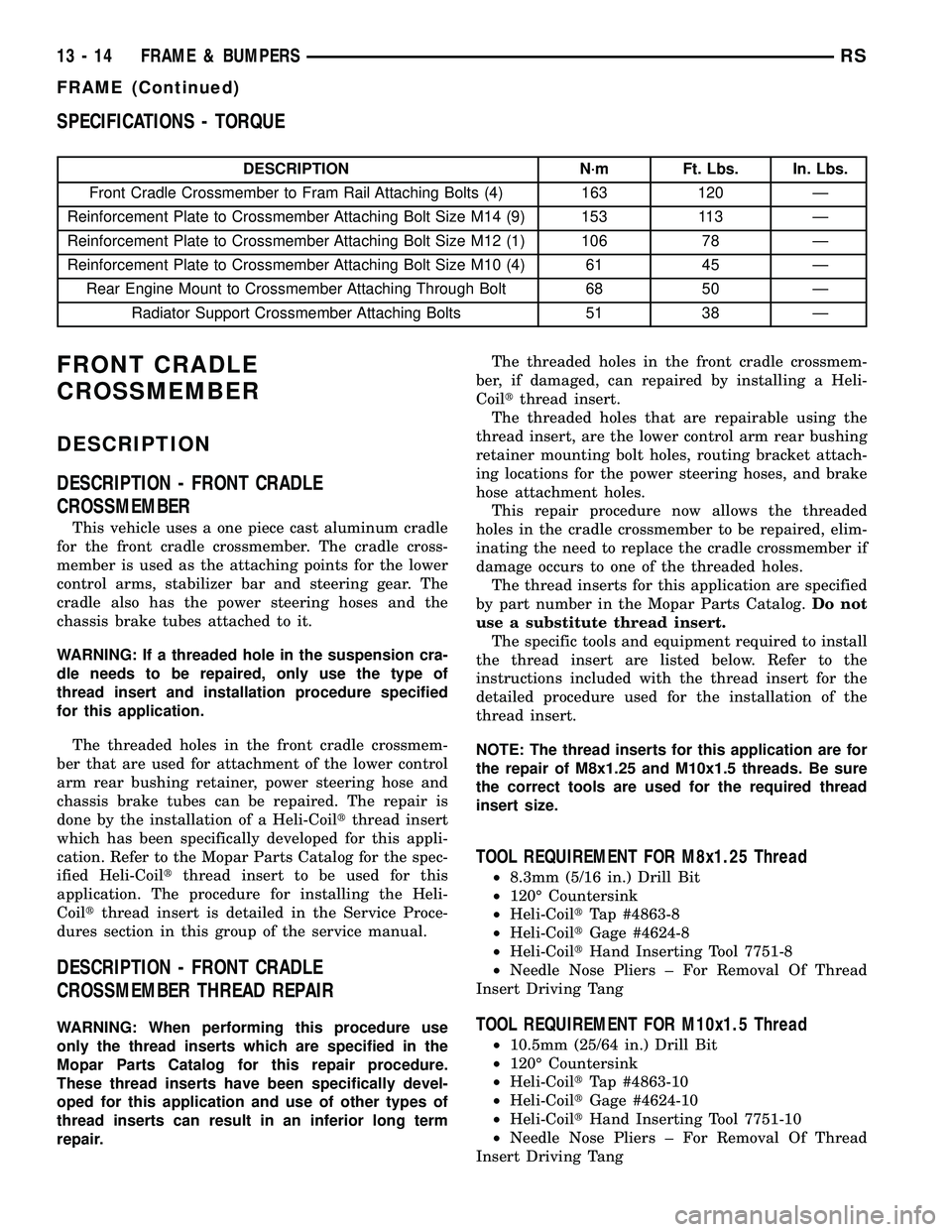
SPECIFICATIONS - TORQUE
DESCRIPTION N´m Ft. Lbs. In. Lbs.
Front Cradle Crossmember to Fram Rail Attaching Bolts (4) 163 120 Ð
Reinforcement Plate to Crossmember Attaching Bolt Size M14 (9) 153 113 Ð
Reinforcement Plate to Crossmember Attaching Bolt Size M12 (1) 106 78 Ð
Reinforcement Plate to Crossmember Attaching Bolt Size M10 (4) 61 45 Ð
Rear Engine Mount to Crossmember Attaching Through Bolt 68 50 Ð
Radiator Support Crossmember Attaching Bolts 51 38 Ð
FRONT CRADLE
CROSSMEMBER
DESCRIPTION
DESCRIPTION - FRONT CRADLE
CROSSMEMBER
This vehicle uses a one piece cast aluminum cradle
for the front cradle crossmember. The cradle cross-
member is used as the attaching points for the lower
control arms, stabilizer bar and steering gear. The
cradle also has the power steering hoses and the
chassis brake tubes attached to it.
WARNING: If a threaded hole in the suspension cra-
dle needs to be repaired, only use the type of
thread insert and installation procedure specified
for this application.
The threaded holes in the front cradle crossmem-
ber that are used for attachment of the lower control
arm rear bushing retainer, power steering hose and
chassis brake tubes can be repaired. The repair is
done by the installation of a Heli-Coiltthread insert
which has been specifically developed for this appli-
cation. Refer to the Mopar Parts Catalog for the spec-
ified Heli-Coiltthread insert to be used for this
application. The procedure for installing the Heli-
Coiltthread insert is detailed in the Service Proce-
dures section in this group of the service manual.
DESCRIPTION - FRONT CRADLE
CROSSMEMBER THREAD REPAIR
WARNING: When performing this procedure use
only the thread inserts which are specified in the
Mopar Parts Catalog for this repair procedure.
These thread inserts have been specifically devel-
oped for this application and use of other types of
thread inserts can result in an inferior long term
repair.The threaded holes in the front cradle crossmem-
ber, if damaged, can repaired by installing a Heli-
Coiltthread insert.
The threaded holes that are repairable using the
thread insert, are the lower control arm rear bushing
retainer mounting bolt holes, routing bracket attach-
ing locations for the power steering hoses, and brake
hose attachment holes.
This repair procedure now allows the threaded
holes in the cradle crossmember to be repaired, elim-
inating the need to replace the cradle crossmember if
damage occurs to one of the threaded holes.
The thread inserts for this application are specified
by part number in the Mopar Parts Catalog.Do not
use a substitute thread insert.
The specific tools and equipment required to install
the thread insert are listed below. Refer to the
instructions included with the thread insert for the
detailed procedure used for the installation of the
thread insert.
NOTE: The thread inserts for this application are for
the repair of M8x1.25 and M10x1.5 threads. Be sure
the correct tools are used for the required thread
insert size.
TOOL REQUIREMENT FOR M8x1.25 Thread
²8.3mm (5/16 in.) Drill Bit
²120É Countersink
²Heli-CoiltTap #4863-8
²Heli-CoiltGage #4624-8
²Heli-CoiltHand Inserting Tool 7751-8
²Needle Nose Pliers ± For Removal Of Thread
Insert Driving Tang
TOOL REQUIREMENT FOR M10x1.5 Thread
²10.5mm (25/64 in.) Drill Bit
²120É Countersink
²Heli-CoiltTap #4863-10
²Heli-CoiltGage #4624-10
²Heli-CoiltHand Inserting Tool 7751-10
²Needle Nose Pliers ± For Removal Of Thread
Insert Driving Tang
13 - 14 FRAME & BUMPERSRS
FRAME (Continued)
Page 1372 of 2339
(4) Install level sensor wires in connector. Push
the wires up through the connector and then pull
them down until they lock in place. Ensure signal
and ground wires are installed in the correct posi-
tion.
(5) Install locking wedge on connector.
(6) Push connector up into bottom of fuel pump
module electrical connector.
(7) Install fuel pump module. Refer to Fuel Pump
Module in this section.
FUEL LINES
DESCRIPTION - FUEL LINES/HOSES AND
CLAMPS
Also refer to Quick-Connect Fittings.
WARNING: THE FUEL SYSTEM IS UNDER A CON-
STANT PRESSURE (EVEN WITH THE ENGINE OFF).
BEFORE SERVICING ANY FUEL SYSTEM HOSES,
FITTINGS OR LINES, THE FUEL SYSTEM PRES-
SURE MUST BE RELEASED. REFER TO THE FUEL
SYSTEM PRESSURE RELEASE PROCEDURE IN
THIS GROUP. THIS MAY RESULT IN PERSONAL
INJURY OR DEATH.
The lines/tubes/hoses used on fuel injected vehicles
are of a special construction. This is due to the
higher fuel pressures and the possibility of contami-
nated fuel in this system. If it is necessary to replace
these lines/tubes/hoses, use new original equipment
lines/tubes/hoses.
If equipped:The hose clamps used to secure rub-
ber hoses on vehicles are of a special rolled edge con-
struction. This construction is used to prevent the
edge of the clamp from cutting into the hose. Only
these rolled edge type clamps may be used in this
system. All other types of clamps may cut into the
hoses and cause leaks.
Use new original equipment type hose clamps.
STANDARD PROCEDURE - HOSES AND CLAMP
Inspect all hose connections (clamps and quick con-
nect fittings) for completeness and leaks. Replace
cracked, scuffed, or swelled hoses. Replace hoses that
rub against other vehicle components or show sign of
wear.
Fuel injected vehicles use specially constructed
hoses. When replacing hoses, only use hoses marked
EFM/EFI.
When installing hoses, ensure that they are routed
away from contact with other vehicle components
that could rub against them and cause failure. Avoid
contact with clamps or other components that causeabrasions or scuffing. Ensure that rubber hoses are
properly routed and avoid heat sources.
The hose clamps have rolled edges to prevent the
clamp from cutting into the hose. Only use clamps
that are original equipment or equivalent. Other
types of clamps may cut into the hoses and cause
high pressure fuel leaks. Tighten hose clamps to 1
N´m (9 in. lbs.) torque.
Inspect all hose connections such as clamps, cou-
plings and fittings to make sure they are secure and
leaks are not present. The component should be
replaced immediately if there is any evidence of deg-
radation that could result in failure.
Never attempt to repair a plastic fuel line/tube.
Replace as necessary.
Avoid contact of any fuel tubes/hoses with other
vehicle components that could cause abrasions or
scuffing. Be sure that the plastic fuel lines/tubes are
properly routed to prevent pinching and to avoid heat
sources.
FUEL PRESSURE REGULATOR
OPERATION
The fuel system uses a nonadjustable pressure reg-
ulator that maintains fuel system pressure at
approximately 400 34 kPa (58 5 psi). The fuel
pressure regulator contains a diaphragm, calibrated
spring and a fuel return valve. The spring pushes
down on the diaphragm and closes off the fuel return
port. System fuel pressure reflects the amount of fuel
pressure required to open the return port.
The pressure regulator is a mechanical device that
is NOT controlled by the PCM or engine vacuum.
REMOVAL
The fuel pressure regulator is part of the fuel
pump module (Fig. 9). Remove the fuel pump module
from the fuel tank to access the fuel pressure regula-
tor. Refer to the Fuel Pump Module removal in this
section.
(1) Squeeze tangs on pressure regulator retainer
and pull to remove retainer.
(2) Pry fuel pressure regulator out of housing.
(3) Ensure both upper and lower O-rings were
removed with regulator.
INSTALLATION
The fuel pressure regulator is part of the fuel
pump module. Remove the fuel pump module from
the fuel tank to access the fuel pressure regulator.
Refer to the Fuel Pump Module removal in this sec-
tion.
RSFUEL DELIVERY14-7
FUEL LEVEL SENDING UNIT / SENSOR (Continued)
Page 1408 of 2339

STEERING
TABLE OF CONTENTS
page page
STEERING
DESCRIPTION - POWER STEERING SYSTEM . . 1
OPERATION - POWER STEERING SYSTEM . . . 1
DIAGNOSIS AND TESTING
DIAGNOSIS AND TESTING - POWER
STEERING SYSTEM FLOW AND
PRESSURE TEST......................1
DIAGNOSIS AND TESTING - STEERING
SYSTEM DIAGNOSIS CHARTS............3SPECIFICATIONS
POWER STEERING FASTENER TORQUE . . . 9
SPECIAL TOOLS
POWER STEERING....................9
COLUMN..............................10
GEAR.................................26
PUMP.................................36
STEERING
DESCRIPTION - POWER STEERING SYSTEM
This vehicle comes with power steering as stan-
dard equipment. The power steering system consists
of these major components:
²POWER STEERING PUMP
²POWER STEERING GEAR
²POWER STEERING FLUID
²POWER STEERING FLUID COOLER (If
Equipped)
²POWER STEERING FLUID RESERVOIR
²POWER STEERING FLUID SUPPLY HOSE
²POWER STEERING FLUID PRESSURE HOSE
²POWER STEERING FLUID RETURN HOSE
For information on the first two components, refer
to their respective sections within this service man-
ual group. Information on all other components can
be found in POWER STEERING PUMP.
OPERATION - POWER STEERING SYSTEM
Turning of the steering wheel is converted into lin-
ear (side-to-side) travel through the meshing of the
helical pinion teeth with the rack teeth within the
steering gear. The lateral travel pushes and pulls the
tie rods to change the direction of the vehicle's front
wheels.
Power assist steering is provided by a belt driven
rotary type pump. It directs fluid through power
steering fluid hoses to the power steering gear where
it is used to assist the driver's turning effort.
Manual steering control of the vehicle can be main-
tained if power steering assist is lost. However,
under this condition, steering effort is significantly
increased.
DIAGNOSIS AND TESTING
DIAGNOSIS AND TESTING - POWER STEERING
SYSTEM FLOW AND PRESSURE TEST
ALL ENGINES
The following procedure is to be used to test the
operation of the power steering system on this vehi-
cle. This test will provide the flow rate of the power
steering pump along with the maximum relief pres-
sure. This test is to be performed to determine if the
power steering pump or power steering gear is not
functioning properly. The following flow and pressure
test is performed using the Power Steering Analyzer
Kit, Special Tool 6815 (Fig. 1), hoses, Special Tools
6905 and 6959, and fittings from adapter kit, Special
Tool 6893.
Fig. 1 Power Steering Analyzer With Hoses Installed
1 - OUTLET
2 - SPECIAL TOOL 6815
3 - INLET
RSSTEERING19-1
Page 1412 of 2339
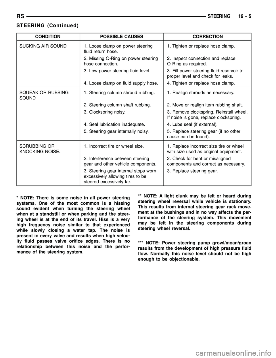
CONDITION POSSIBLE CAUSES CORRECTION
SUCKING AIR SOUND 1. Loose clamp on power steering
fluid return hose.1. Tighten or replace hose clamp.
2. Missing O-Ring on power steering
hose connection.2. Inspect connection and replace
O-Ring as required.
3. Low power steering fluid level. 3. Fill power steering fluid reservoir to
proper level and check for leaks.
4. Loose clamp on fluid supply hose. 4. Tighten or replace hose clamp.
SQUEAK OR RUBBING
SOUND1. Steering column shroud rubbing. 1. Realign shrouds as necessary.
2. Steering column shaft rubbing. 2. Move or realign item rubbing shaft.
3. Clockspring noisy. 3. Remove clockspring. Reinstall wheel.
If noise is gone, replace clockspring.
4. Seal lubrication inadequate. 4. Lube seal (if external).
5. Steering gear internally noisy. 5. Replace steering gear (if no other
cause can be found).
SCRUBBING OR
KNOCKING NOISE.1. Incorrect tire or wheel size. 1. Replace incorrect size tire or wheel
with size used as original equipment.
2. Interference between steering
gear and other vehicle components.2. Check for bent or misaligned
components and correct as necessary.
3. Steering gear internal stops worn
excessively allowing tires to be
steered excessively far.3. Replace steering gear.
* NOTE: There is some noise in all power steering
systems. One of the most common is a hissing
sound evident when turning the steering wheel
when at a standstill or when parking and the steer-
ing wheel is at the end of its travel. Hiss is a very
high frequency noise similar to that experienced
while slowly closing a water tap. The noise is
present in every valve and results when high veloc-
ity fluid passes valve orifice edges. There is no
relationship between this noise and the perfor-
mance of the steering system.** NOTE: A light clunk may be felt or heard during
steering wheel reversal while vehicle is stationary.
This results from internal steering gear rack move-
ment at the bushings and in no way affects the per-
formance of the steering system. This movement
may be felt in the steering components during
steering wheel reversal.
*** NOTE: Power steering pump growl/moan/groan
results from the development of high pressure fluid
flow. Normally this noise level should not be high
enough to be objectionable.
RSSTEERING19-5
STEERING (Continued)
Page 1575 of 2339

OPERATION
The Brake/Transmission Shift Interlock (BTSI)
Solenoid prevents the transmission shift lever from
being moved out of PARK (P) unless the brake pedal
is applied. The BTSI solenoid is hardwired to and
controlled by the Intelligent Power Module (IPM).
Battery voltage is applied to one side of the solenoid
with the ignition key is in either the OFF, ON/RUN,
or START positions (Fig. 269). The ground side of the
solenoid is controlled by a driver within the IPM. It
relies on voltage supplied from the stop lamp switch
to the stop lamp sense circuit within the IPM to tell
when the brake pedal is depressed. When the brake
pedal is depressed, the ground circuit opens, de-ener-
gizing the solenoid. When the brake pedal is
released, the ground circuit is closed, energizing the
solenoid.
When the ignition key is in either the OFF,
ON/RUN, or START positions, the BTSI solenoid is
energized, and the solenoid plunger hook pulls the
shift lever pawl into position, prohibiting the shift
lever from moving out of PARK (P) (Fig. 270). When
the brake pedal is depressed, the ground circuit
opens, de-energizing the solenoid. This moves the
gearshift lever pawl out of the way (Fig. 271), allow-
ing the shift lever to be moved into any gear position.
Fig. 269 Ignition Key/Switch Positions
1 - ACC
2 - LOCK
3 - OFF
4 - ON/RUN
5-START
Fig. 270 Pawl Engaged to Shift Lever
1 - GEAR SHIFT LEVER
2 - GEAR SHIFT LEVER PAWL
Fig. 271 Pawl Disengaged From Shift Lever
1 - GEAR SHIFT LEVER
2 - GEAR SHIFT LEVER PAWL
21 - 114 40TE AUTOMATIC TRANSAXLERS
SHIFT INTERLOCK SOLENOID (Continued)
Page 1591 of 2339

TRANSMISSION CONTROL
RELAY
DESCRIPTION
The transmission control relay (Fig. 306) is located
in the Intelligent Power Module (IPM), which is
located on the left side of the engine compartment
between the battery and left fender.
OPERATION
The relay is supplied fused B+ voltage, energized by
the PCM/TCM, and is used to supply power to the sole-
noid pack when the transmission is in normal operating
mode. When the relay is ªoffº, no power is supplied to
the solenoid pack and the transmission is in ªlimp-inº
mode. After a controller reset (ignition key turned to the
ªrunº position or after cranking engine), the PCM/TCM
energizes the relay. Prior to this, the PCM/TCM verifies
that the contacts are open by checking for no voltage at
the switched battery terminals. After this is verified,
the voltage at the solenoid pack pressure switches is
checked. After the relay is energized, the PCM/TCM
monitors the terminals to verify that the voltage is
greater than 3 volts.
TRANSMISSION RANGE
SENSOR
DESCRIPTION
The Transmission Range Sensor (TRS) is mounted
to the top of the valve body inside the transaxle andcan only be serviced by removing the valve body. The
electrical connector extends through the transaxle
case (Fig. 307).
The Transmission Range Sensor (TRS) has four
switch contacts that monitor shift lever position and
send the information to the PCM/TCM.
The TRS also has an integrated temperature sen-
sor (thermistor) that communicates transaxle tem-
perature to the TCM and PCM (Fig. 308).
Fig. 306 Transmission Control Relay Location
1 - TRANSMISSION CONTROL RELAY
2 - LEFT FENDER
3 - INTELLIGENT POWER MODULE (IPM)
4 - BATTERY
Fig. 307 Transmission Range Sensor (TRS)
Location
1 - TRANSMISSION RANGE SENSOR
Fig. 308 Transmission Temperature Sensor
1 - TRANSMISSION RANGE SENSOR
2 - TEMPERATURE SENSOR
21 - 130 40TE AUTOMATIC TRANSAXLERS