ipm CHRYSLER VOYAGER 2005 Repair Manual
[x] Cancel search | Manufacturer: CHRYSLER, Model Year: 2005, Model line: VOYAGER, Model: CHRYSLER VOYAGER 2005Pages: 2339, PDF Size: 59.69 MB
Page 464 of 2339
travel. This allows the power sliding door to stop and
reverse direction any time an obstruction is felt or
any of the command switches are operated (while
closing only). Battery voltage is supplied to the power
sliding door system through a 40 amp fuse, located in
the Integrated Power Module (IPM) assembly. The
child lockout switch prevents children from opening
or actuating the power sliding door system when
desired. In the unlikely event that the power sliding
door system develops a fault, the power sliding door
can still be operated manually from the interior or
exterior door handle, just like a standard manual
sliding door.
The power sliding door control module communi-
cates on the Programmable Communication Interface
(PCI) Data Bus Circuit. Therefore, the power sliding
door control module can generate and store its own
Diagnostic Trouble Codes (DTC). A diagnostic scan
tool, such as the DRB IIItis used to read and diag-
nose these trouble codes.
NOTE: It may be possible to generate Sliding Door
Diagnostic Trouble Codes during normal power
sliding door operation. Refer to the Body Diagnos-
tic Manual for a complete list of diagnostic routines.
For additional information, (Refer to 8 - ELECTRI-
CAL/POWER DOORS - OPERATION). Refer to the
appropriate wiring information for complete circuit
schematic or connector pin-out information.WARNING: BE CERTAIN TO READ ALL WARNINGS
AND CAUTIONS IN POWER SLIDING DOOR OPER-
ATION BEFORE ATTEMPTING ANY SERVICE OF
THE POWER SLIDING DOOR SYSTEM OR COMPO-
NENTS.
OPERATION
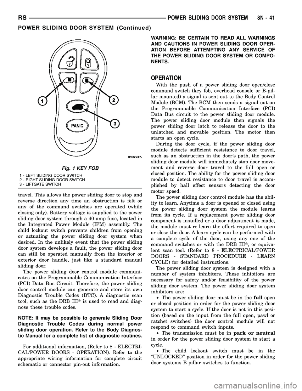
With the push of a power sliding door open/close
command switch (key fob, overhead console or B-pil-
lar mounted) a signal is sent out to the Body Control
Module (BCM). The BCM then sends a signal out on
the Programmable Communication Interface (PCI)
Data Bus circuit to the power sliding door module.
The power sliding door module then signals the
power sliding door latch to release the door to the
unlatched and movable position. The motor then
starts an open cycle.
During the door cycle, if the power sliding door
module detects sufficient resistance to door travel,
such as an obstruction in the door's path, the power
sliding door module will immediately stop door move-
ment and reverse door travel to the full open or
closed position. The ability for the power sliding door
module to detect resistance to door travel is accom-
plished by hall effect sensors detecting the door
motor speed.
The power sliding door control module has the abil-
ity to learn. Anytime a door is opened or closed using
the power sliding door system the module learns
from its cycle. If a replacement power sliding door
component is installed or a door adjustment is made,
the module must re-learn the effort required to open
or close the door. A learn cycle can be performed with
a complete cycle of the door, using any one of the
command switches or with the DRB IIIt, or equiva-
lent scan tool. (Refer to 8 - ELECTRICAL/POWER
DOORS - STANDARD PROCEDURE - LEARN
CYCLE) for detailed instructions.
The power sliding door system is designed with a
number of system inhibitors. These inhibitors are
necessary for safety and/or feasibility of the power
sliding door system. The power sliding door system
inhibitors are:
²The power sliding door must be in thefullopen
or closed position in order for the power sliding door
system to start a cycle. If the door is not in this posi-
tion (based on the input from the full open, pawl or
ratchet switches) the door control module will not
respond to command switch inputs.
²The transmission must be inpark or neutral
in order for the power sliding door system to start a
cycle.
²The child lockout switch must be in the
ªUNLOCKEDº position in order for the power sliding
door systems B-pillar switches to function.
Fig. 1 KEY FOB
1 - LEFT SLIDING DOOR SWITCH
2 - RIGHT SLIDING DOOR SWITCH
3 - LIFTGATE SWITCH
RSPOWER SLIDING DOOR SYSTEM8N-41
POWER SLIDING DOOR SYSTEM (Continued)
Page 485 of 2339

(3) Switch ignition ON position.
(4) Connect the clip end of a 12 volt test light to
Pin 13 in door harness connector at the window
switch. Touch the test light probe to Pin 9 and then
to Pin 11.
²If the test light illuminates, the wiring circuit
between the battery and switch is OK.
²If the lamp does not illuminate, first check the
25 amp circuit breaker attached to the electrical dis-
tribution wiring bracket. If the circuit breaker is OK,
then check the 40 amp fuse (#28) in the Integrated
Power Module (IPM). If both components are OK,
then check for a broken wire.
VENT WINDOW MOTOR
DIAGNOSIS AND TESTING
VENT WINDOW MOTOR
If the power vent window motor is receiving proper
current and ground and does not operate proceed
with motor test. Refer to the appropriate wiring
information.
(1) Remove D-pillar trim panel necessary to gain
access to power vent window motor wire connector,
(Refer to 23 - BODY/INTERIOR/LEFT D-PILLAR
TRIM PANEL - REMOVAL) or (Refer to 23 - BODY/
INTERIOR/RIGHT D-PILLAR TRIM PANEL -
REMOVAL).
(2) Disconnect power vent window motor wire con-
nector from body harness.
(3) Using two jumper wires, connect one to a bat-
tery (+) source and the other to a good ground (-).
(4) Connect the Negative (-) jumper probe to one of
the motor connector terminals.
(5) Momentarily touch the Positive (+) jumper
probe to the other motor connector terminal.
When positive probe is connected the motor should
rotate in one direction to either move window open or
closed. If window is all the way open or closed the
motor will grunt and the crank system will flex when
actuated in that one direction.
Reverse jumper probes at the motor connector ter-
minals and window should now move in opposite
direction. If window does not move or grunt, replace
the motor.
If window moved completely open or closed, reverse
the jumper probes and cycle window to the opposite
position to verify full operation.
If motor grunts and does not move, verify that
crank system is not binding.
REMOVAL
(1) Disconnect and isolate the battery negative
cable.(2) Remove D-pillar trim panel. (Refer to 23 -
BODY/INTERIOR/LEFT D-PILLAR TRIM PANEL -
REMOVAL) or (Refer to 23 - BODY/INTERIOR/
RIGHT D-PILLAR TRIM PANEL - REMOVAL).
(3) Disconnect wire connector from power vent
motor.
(4) Using a flat bladed tool, carefully lift the circu-
lar actuator link tab. Remove link from window ball
socket.
(5) Remove bolts holding power vent motor to
D-pillar (Fig. 1).
(6) Remove power vent motor.
INSTALLATION
(1) Obtain new vent window motor.
(2) Snap the actuator link socket onto the quarter
window ball socket. Using a soft rubber mallet, push
the circular link tab flush with link surface.
(3) Install bolts holding power vent motor to D-pil-
lar.
(4) Reconnect wire connector to power vent motor.
(5) Reconnect the battery negative cable.
(6) Cycle quarter window open/close to verify func-
tion.
(7) Install D-pillar trim panel.
WINDOW MOTOR
REMOVAL
The window motor is incorporated into the window
regulator assembly. If the window motor requires
replacement, the window regulator must be replaced.
(Refer to 23 - BODY/DOOR - FRONT/WINDOW
REGULATOR - REMOVAL).
Fig. 1 VENT WINDOW MOTOR
1 - VENT WINDOW MOTOR
2 - WIRE HARNESS CONNECTOR
3 - BOLT
4 - VENT WINDOW
8N - 62 POWER WINDOWSRS
POWER WINDOWS (Continued)
Page 489 of 2339
SEAT BELT & RETRACTOR - SECOND ROW -
RIGHT OUTBOARD
REMOVAL.............................40
INSTALLATION.........................40
SEAT BELT & RETRACTOR - SECOND ROW -
RIGHT OUTBOARD WITH REAR HVAC - LWB
REMOVAL.............................41
INSTALLATION.........................41
SEAT BELT & RETRACTOR - SECOND ROW -
LEFT OUTBOARD
REMOVAL.............................42INSTALLATION.........................42
SEAT BELT TENSIONER
DESCRIPTION.........................43
OPERATION...........................43
SEAT WEIGHT BLADDER & PRESSURE
SENSOR
DESCRIPTION.........................43
OPERATION...........................44
RESTRAINTS
DESCRIPTION
This vehicle is equipped with a Frontal Impact Air-
bag System, which utilizes the driver/passenger air-
bags, two front impact sensors, and seat belt
tensioners located in the front seat belt buckles. This
system is designed to protect occupants in the event
of a front impact collision. These airbags are all ser-
viceable parts. The tensioners are integral to the
front seat belt buckles. If these pyrotechnics are
deployed or defective, they must be replaced.
Vehicles equipped with the Side Impact Airbag
System utilize a curtain airbag, three side impact
sensors, and the Occupant Restraint Controller
(ORC) to determine if the airbag should be deployed.
Following a side impact event where the side airbag
was deployed, the headliner as well as the curtain
airbag must be replaced.
The occupant restraints include both active and
passive types. Active restraints are those which
require the vehicle occupants to take some action to
employ, such as fastening a seat belt; while passive
restraints require no action by the vehicle occupants
to be employed.
ACTIVE RESTRAINTS
The active restraints include:
²Front Seat Belts- Both front seating positions
are equipped with three-point seat belt systems
employing a lower B-pillar mounted inertia latch-
type retractor, height-adjustable upper B-pillar
mounted turning loops, a fixed lower seat belt anchor
secured to the lower B-pillar, and a traveling end-re-
lease buckle secured to the inboard side of the seat
cushion frame. The driver side front seat belt buckle
includes an integral Hall-effect seat belt switch that
detects whether the driver side front seat belt has
been fastened.²Rear Seat Belts- Both outboard rear second
and third seating positions are equipped with three-
point seat belt systems. The outboard seating posi-
tion belts employ a lower C or D-pillar mounted
inertia latch-type retractor, a fixed position upper C
or D-pillar mounted turning loop, and a fixed lower
seat belt anchor secured to the inboard side of the
seat cushion frame.
²Child Restraint Anchors- Also equipped in
this vehicle are two, fixed-position, child seat upper
tether anchors located on the lower seat cushion, in
the rear of the lower seat cushion. There is one
anchor integral to the back of the third row seat back
panel, one on each seat back panel. Two lower second
row anchors are also provided for each rear outboard
seating position. The lower anchors are integral to
the seat cushion frame and are accessed from the
front of the second row seat where the seat back
meets the seat cushion.
PASSIVE RESTRAINTS
The passive restraints available for this model
include the following:
²Dual Front Airbags- Multistage driver. front
passenger, and driver knee blocker airbags are avail-
able for this model. This airbag system is a passive,
inflatable, Supplemental Restraint System (SRS) and
vehicles with this equipment can be readily identified
by the ªSRS - AIRBAGº logo molded into the driver
airbag trim cover in the center of the steering wheel
and also into the passenger airbag door on the
instrument panel above the glove box. Vehicles with
the airbag system can also be identified by the airbag
indicator, which will illuminate in the instrument
cluster for about seven seconds as a bulb test each
time the ignition switch is turned to the ON position.
A pyrotechnic-type seat belt tensioner is integral to
the driver and passenger front seat belt buckle of all
models equipped with dual front airbags.
8O - 2 RESTRAINTSRS
Page 490 of 2339
²Occupant Classification System- These
vehicles also include an Occupant Classification Sys-
tem (OCS) with components that are located on or in
the passenger front seat cushion. These components
include an Occupant Classification Module (OCM)
and a seat weight bladder and pressure sensor
assembly. In addition, this system includes a belt
tension sensor integral to the lower anchor of the
passenger side front seat belt. Vehicles equipped with
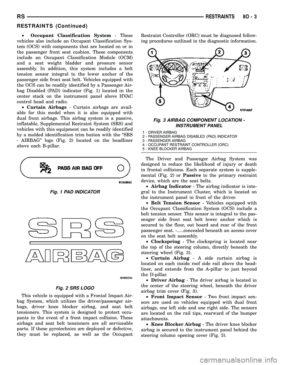
the OCS can be readily identified by a Passenger Air-
bag Disabled (PAD) indicator (Fig. 1) located in the
center stack on the instrument panel above HVAC
control head and radio.
²Curtain Airbags- Curtain airbags are avail-
able for this model when it is also equipped with
dual front airbags. This airbag system is a passive,
inflatable, Supplemental Restraint System (SRS) and
vehicles with this equipment can be readily identified
by a molded identification trim button with the ªSRS
- AIRBAGº logo (Fig. 2) located on the headliner
above each B-pillar.
This vehicle is equipped with a Frontal Impact Air-
bag System, which utilizes the driver/passenger air-
bags, driver knee blocker airbag, and seat belt
tensioners. This system is designed to protect occu-
pants in the event of a front impact collision. These
airbags and seat belt tensioners are all serviceable
parts. If these pyrotechnics are deployed or defective,
they must be replaced, as well as the OccupantRestraint Controller (ORC) must be diagnosed follow-
ing procedures outlined in the diagnostic information.
The Driver and Passenger Airbag System was
designed to reduce the likelihood of injury or death
in frontal collisions. Each separate system is supple-
mental (Fig. 2) orPassiveto the primary restraint
device, which are the seat belts.
²Airbag Indicator- The airbag indicator is inte-
gral to the Instrument Cluster, which is located on
the instrument panel in front of the driver.
²Belt Tension Sensor- Vehicles equipped with
the Occupant Classification System (OCS) include a
belt tension sensor. This sensor is integral to the pas-
senger side front seat belt lower anchor which is
secured to the floor, out board and rear of the front
passenger seat. -.....concealed beneath an access cover
on the seat belt assembly.
²Clockspring- The clockspring is located near
the top of the steering column, directly beneath the
steering wheel (Fig. 3).
²Curtain Airbag- A side curtain airbag is
located on each inside roof side rail above the head-
liner, and extends from the A-pillar to just beyond
the D-pillar.
²Driver Airbag- The driver airbag is located in
the center of the steering wheel, beneath the driver
airbag trim cover (Fig. 3).
²Front Impact Sensor- Two front impact sen-
sors are used on vehicles equipped with dual front
airbags, one left side and one right side. The sensors
are located on the rail tips, rearward of the bumper
attachments.
²Knee Blocker Airbag- The driver knee blocker
airbag is secured to the instrument panel behind the
steering column opening cover (Fig. 3).
Fig. 1 PAD INDICATOR
Fig. 2 SRS LOGO
Fig. 3 AIRBAG COMPONENT LOCATION -
INSTRUMENT PANEL
1 - DRIVER AIRBAG
2 - PASSENGER AIRBAG DISABLED (PAD) INDICATOR
3 - PASSENGER AIRBAG
4 - OCCUPANT RESTRAINT CONTROLLER (ORC)
5 - KNEE BLOCKER AIRBAG
RSRESTRAINTS8O-3
RESTRAINTS (Continued)
Page 493 of 2339
experienced, exit the vehicle for fresh air until
the irritation ceases. If irritation continues, see
a physician.
Do not use a replacement airbag that is not in
the original packaging. This may result in
improper deployment, personal injury, or
death.
The factory installed fasteners, screws and
bolts used to fasten airbag components have a
special coating and are specifically designed
for the airbag system. Do not use substitute fas-
teners. Use only original equipment fasteners
listed in the parts catalog when fastener
replacement is required.
During, and following, any child restraint
anchor service, due to impact event or vehicle
repair, carefully inspect all mounting hard-
ware, tether straps, and anchors for proper
installation, operation, or damage. If a child
restraint anchor is found damaged in any way,
the anchor must be replaced. Failure to do this
may result in personal injury or death.
Deployed and nondeployed airbags may or
may not have live pyrotechnic material within
the airbag inflator. Do not dispose of driver/
passenger/seat/curtain/knee blocker airbags or
seat belt tensioners unless you are sure of com-
plete deployment. Refer to the Hazardous Sub-
stance Control System for proper disposal.
Dispose of deployed airbags and tensioners
consistent with state, provincial, local, and fed-
eral regulations.
After any airbag component testing or ser-
vice, do not connect the battery negative cable
(Refer to 8 - ELECTRICAL/RESTRAINTS -
DIAGNOSIS AND TESTING - AIRBAG SYSTEM).
Personal injury or death may result if the sys-
tem test is not performed first.
If the vehicle is equipped with the Occupant
Classification System (OCS), do not connect the
battery negative cable before performing the
OCS Verification Test using the scan tool and
the appropriate diagnostic information. Per-
sonal injury or death may result if the system
test is not performed properly.
Never replace both the Occupant Restraint
Controller (ORC) and the Occupant Classifica-
tion Module (OCM) at the same time. If both
require replacement, replace one, then perform
the Airbag System test (Refer to 8 - ELECTRI-
CAL/RESTRAINTS - DIAGNOSIS AND TESTING
- AIRBAG SYSTEM) before replacing the other.
Both the ORC and the OCM store Occupant
Classification System (OCS) calibration data,
which they transfer to one another when one of
them is replaced. If both are replaced at thesame time, an irreversible fault will be set in
both modules and the OCS may malfunction
and cause personal injury or death.
DIAGNOSIS AND TESTING - AIRBAG SYSTEM
(1) With the battery negative remote cable discon-
nected, connect the scan tool to the Data Link Con-
nector (DLC).
(2) Turn the ignition key to the ON position, then
exit vehicle with the scan tool.
(3) After checking that no one is inside the vehicle,
connect the battery negative remote terminal.
(4) Read and record theACTIVEDiagnostic Trou-
ble Code (DTC) data.
(5) Read and record anySTOREDDTC's.
(6) Refer to the proper diagnostic information if
any DTC's are found in Step 4 and Step 5.
(7) If the airbag warning lamp either fails to light,
or goes ON and stays ON, there is a system malfunc-
tion. To test the airbag warning lamp (bulb) opera-
tion in the cluster (Refer to 8 - ELECTRICAL/
INSTRUMENT CLUSTER - DIAGNOSIS AND
TESTING). Refer to the proper diagnostic informa-
tion for any other system problems.
STANDARD PROCEDURE
STANDARD PROCEDURE - HANDLING
AIRBAGS
DEPLOYED AIRBAG
WARNING: The vehicle interior may contain a very
small amount of powder, a by-product of airbag
deployment. This powder can irritate the skin, eyes,
nose and throat. Wear safety glasses, rubber
gloves, and long sleeved clothing when cleaning
any of the powder residue from the vehicle. If you
find that the cleanup is irritating your skin, run cool
water over the affected area. Also, if you experience
nasal or throat irritation, exit the vehicle for fresh
air until the irritation ceases. If irritation continues,
see a physician.
8O - 6 RESTRAINTSRS
RESTRAINTS (Continued)
Page 498 of 2339
Service replacement clocksprings are shipped pre-
centered and with a molded plastic shield that snaps
onto the rotor over the release button. The release
button secures the centered clockspring rotor to the
clockspring case and the shield prevents the release
button from being inadvertently depressed during
shipment and handling, but the shield must be
removed from the clockspring after it is installed on
the steering column (Refer to 8 - ELECTRICAL/RE-
STRAINTS/CLOCKSPRING - STANDARD PROCE-
DURE).
The clockspring cannot be repaired. If the clock-
spring is faulty, damaged, or if the driver airbag has
been deployed, the clockspring must be replaced.
OPERATION
The clockspring is a mechanical electrical circuit
component that is used to provide continuous electri-
cal continuity between the fixed instrument panel
wire harness and the electrical components mounted
on or in the rotating steering wheel. The rotating
electrical components include the driver airbag, the
horn switch, the speed control switches, and the
remote radio switches, if the vehicle is so equipped.
The clockspring case is positioned and secured to the
upper steering column housing near the top of the
steering column. The connector receptacles on the
tail of the clockspring case connect the clockspring to
the vehicle electrical system through two connectors
from the instrument panel wire harness.
The clockspring rotor is movable and is keyed by
the tower formation that is molded onto the upper
surface of the rotor hub to an opening that is cast
into the steering wheel armature. Rubber bumper
blocks on either side of the clockspring tower forma-
tion eliminate contact noise between the clockspring
tower and the steering wheel. The lobe of the turn
signal cancel cam on the lower surface of the clock-
spring rotor hub contacts a turn signal cancel actua-
tor of the multi-function switch to provide automatic
turn signal cancellation. The yellow or black-sleeved
pigtail wires on the upper surface of the clockspring
rotor connect the clockspring to the driver airbag,
while a steering wheel wire harness connects the
connector receptacle on the upper surface of the
clockspring rotor to the horn switch and, if the vehi-
cle is so equipped, to the optional speed control
switches and remote radio switches on the steering
wheel.
The clockspring tape has travel limits and can be
damaged by being wound too tightly during full stop-
to-stop steering wheel rotation. To prevent this from
occurring, the clockspring is centered when it is
installed on the steering column. Centering the clock-
spring indexes the clockspring tape to the movable
steering components so that the tape can operatewithin its designed travel limits. However, if the
clockspring is removed from the steering column or if
the steering shaft is disconnected from the steering
gear, the clockspring spool can change position rela-
tive to the movable steering components and must be
re-centered following completion of the service or the
tape may be damaged (Refer to 8 - ELECTRICAL/
RESTRAINTS/CLOCKSPRING - STANDARD PRO-
CEDURE).
Service replacement clocksprings are shipped pre-
centered and with a plastic shield installed over the
clockspring release button. This shield should not be
removed and the release button should not be
depressed until the clockspring has been installed on
the steering column. If the release button is
depressed before the clockspring is installed on a
steering column, the clockspring centering procedure
must be performed (Refer to 8 - ELECTRICAL/RE-
STRAINTS/CLOCKSPRING - STANDARD PROCE-
DURE).
STANDARD PROCEDURE - CLOCKSPRING
CENTERING
If the rotating tape (wire coil) in the clockspring is
not positioned properly with the steering wheel and
the front wheels, the clockspring may fail. The fol-
lowing procedure MUST BE USED to center the
clockspring if it is not known to be properly posi-
tioned, or if the front wheels were moved from the
straight ahead position.
(1) Position steering wheel and front wheels
straight ahead.
(2) Release hood latch and open hood.
(3) Disconnect and isolate the battery negative
cable.
(4) Wait two minutes for the system reserve capac-
itor to discharge before beginning any airbag compo-
nent service.
(5) Remove driver airbag from steering wheel
(Refer to 8 - ELECTRICAL/RESTRAINTS/DRIVER
AIRBAG - REMOVAL).
(6) Disconnect wire connectors from back of driver
airbag.
(7) Disconnect the 2±way connector from remote
radio control harness (if equipped).
(8) Disconnect the 4±way harness connector from
the speed control (if equipped)/horn harness to the
clockspring.
(9) Remove steering wheel (Refer to 19 - STEER-
ING/COLUMN/STEERING WHEEL - REMOVAL).
(10) Rotate the clockspring rotor clockwise until
the rotor stops. Do not apply excessive force.
(11) From the end of travel, rotate the rotor two
turns counterclockwise until the wires end up at the
top.
RSRESTRAINTS8O-11
CLOCKSPRING (Continued)
Page 499 of 2339
(12) Install the steering wheel (Refer to 19 -
STEERING/COLUMN/STEERING WHEEL -
INSTALLATION).
(13) Connect the 4±way harness connector to the
speed control/horn harness to the clockspring.
(14) Connect the 2±way connector to the remote
radio control harness.
(15) Install the driver airbag (Refer to 8 - ELEC-
TRICAL/RESTRAINTS/DRIVER AIRBAG - INSTAL-
LATION). Torque the two screws to 10 N´m (90 in.
lbs.).
WARNING: Do not connect the battery negative
cable (Refer to 8 - ELECTRICAL/RESTRAINTS -
DIAGNOSIS AND TESTING). Personal injury or
death may result if the system test is not performed
properly.
REMOVAL
(1) Position steering wheel and front wheels
straight ahead.
(2) Release hood latch and open hood.
(3) Disconnect and isolate the battery negative
cable.
(4)
WARNING: Wait two minutes for the airbag system
reserve capacitor to discharge before beginning
any airbag system or component service. Failure to
do so may result in accidental airbag deployment,
personal injury or death.
(5) Remove driver airbag from steering wheel
(Refer to 8 - ELECTRICAL/RESTRAINTS/DRIVER
AIRBAG - REMOVAL).
(6) Disconnect wire connectors from back of driver
airbag.
(7) Disconnect the 2±way connector from remote
radio control harness.
(8) Disconnect the 4±way harness connector from
the speed control/horn harness to the clockspring.
(9) Remove steering wheel (Refer to 19 - STEER-
ING/COLUMN/STEERING WHEEL - REMOVAL).
(10) Remove steering column shrouds and discon-
nect traction control wire connector (if equipped)
(Refer to 19 - STEERING/COLUMN/LOWER
SHROUD - REMOVAL).
(11) Disconnect 4-way and 6-way connectors
between the clockspring and the instrument panel
wiring harness.
(12) Remove clockspring from column assembly by
removing the two retaining screws that attach the
clock spring to the column.
INSTALLATION
(1) Install the clockspring on the column.
(2) Connect the 4-way and 6-way connectors
between the clockspring and the instrument panel
wiring harness.
(3) Install the steering column shrouds and con-
nect traction control wire connector (if equipped)
(Refer to 19 - STEERING/COLUMN/LOWER
SHROUD - INSTALLATION).
(4) Install the steering wheel (Refer to 19 -
STEERING/COLUMN/STEERING WHEEL -
INSTALLATION).
(5) Connect the 4±way harness connector to the
speed control/horn harness to the clockspring.
(6) Connect the 2±way connector to the remote
radio control harness (if equipped).
(7) Install the driver airbag (Refer to 8 - ELEC-
TRICAL/RESTRAINTS/DRIVER AIRBAG - INSTAL-
LATION). Torque the two screws to 10 N´m (90 in.
lbs.).
WARNING: Do not connect the battery negative
cable (Refer to 8 - ELECTRICAL/RESTRAINTS -
DIAGNOSIS AND TESTING - AIRBAG SYSTEM). Per-
sonal injury or death may result if the system test
is not performed first.
CURTAIN AIRBAG
DESCRIPTION
Curtain Airbags (Fig. 11) are available when it is
also equipped with dual front airbags. These airbags
are passive and inflatable, Supplemental Restraint
System (SRS) components, and vehicles with this
equipment can be readily identified by a molded
identification trim button with the ªSRS - AIRBAGº
logo (Fig. 12) located on the B-pillar and C-pillar
upper trim panels. This system is designed to reduce
injuries to the vehicle occupants in the event of a
side impact collision.
Curtain airbags have two individually controlled
curtain airbag units. These airbag units are con-
cealed and mounted above the headliner where they
are each secured to one of the roof side rails (Fig.
13). Each airbag cushion is contained within a fabric
wrap that extends along the roof rail from the A-pil-
lar at the front of the vehicle to just behind the
D-pillar at the rear of the vehicle. One tether extends
down the A-pillar from the front of the airbag cush-
ion, and a second tether extends to the roof rail at
the D-pillar. The end of the A-pillar tether is secured
to a slot in the sheet metal with a metal hook
retained by a bolt. The D-pillar tether is attached to
the d-pillar.
8O - 12 RESTRAINTSRS
CLOCKSPRING (Continued)
Page 513 of 2339
anchor. The OCM then monitors the return voltage
from each of the sensors. The bladder pressure sen-
sor input allows the OCM to determine whether the
passenger front seat is occupied and the relative size
of the occupant by providing a weight-sensing refer-
ence to the load on the seat cushion. The belt tension
sensor provides an additional logic input to the OCM
microprocessor that allows it to distinguish between
the lower seat belt cinch loads of a belted occupant
and the higher loads associated with a belted child
seat.
Pre-programmed decision algorithms and OCS cal-
ibration allow the OCM microprocessor to determine
when the seat cushion load as signaled by the blad-
der pressure sensor and the seat belt cinch load as
signaled by the belt tension sensor indicate that pas-
senger airbag protection is appropriate. When the
programmed conditions are met, the OCM sends the
proper electronic occupant classification messages
over the PCI data bus to the Occupant Restraint
Controller (ORC), and the ORC enables or disables
the deployment circuits for the passenger front sup-
plemental restraints. The ORC also provides a con-
trol output for the Passenger Airbag Disabled (PAD)
indicator in the instrument panel center stack, based
upon the electronic occupant classification messages
it receives from the OCM.
The OCM microprocessor continuously monitors all
of the OCS electrical circuits and components to
determine the system readiness. If the OCM detects
a monitored system fault, it sets an active and stored
Diagnostic Trouble Code (DTC) and sends the appro-
priate electronic messages to the ORC over the PCI
data bus. Then the ORC sets a DTC and sends mes-
sages to control the airbag indicator operation
accordingly. An active fault only remains for the
duration of the fault, or in some cases for the dura-
tion of the current ignition switch cycle, while a
stored fault causes a DTC to be stored in memory by
the OCM and the ORC. For some DTC's, if a fault
does not recur for a number of ignition cycles, the
OCM will automatically erase the stored DTC. For
other internal faults, the stored DTC is latched for-
ever.
The OCM receives battery current from an IPM
high side driver (Run/Start). The OCM receives
ground through a ground circuit of the body wire
harness, which it shares with the ORC. These con-
nections allow the OCM to be operational whenever
the ignition switch is in the Start or ON positions.
To diagnose and test the OCS, use a scan tool and
the appropriate diagnostic information.
REMOVAL
Once any of the original factory-installed compo-
nents except the Occupant Classification Module(OCM) have been replaced with the service replace-
ment package components, the OCM can only be ser-
viced by replacing the entire passenger front seat
cushion unit with another complete service replace-
ment package (Refer to 23 - BODY/SEATS/SEAT
CUSHION - FRONT - REMOVAL).
WARNING: Never replace both the Occupant
Restraint Controller (ORC) and the Occupant Clas-
sification Module (OCM) at the same time. If both
require replacement, replace one, then perform the
Airbag System test (Refer to 8 - ELECTRICAL/RE-
STRAINTS - DIAGNOSIS AND TESTING - AIRBAG
SYSTEM) before replacing the other. Both the ORC
and the OCM store Occupant Classification System
(OCS) calibration data, which they transfer to one
another when one of them is replaced. If both are
replaced at the same time, an irreversible fault will
be set in both modules and the OCS may malfunc-
tion and result in personal injury or death.
(1) Disconnect and isolate the battery negative
cable.
(2)
WARNING: Wait two minutes for the airbag system
reserve capacitor to discharge before beginning
any airbag system or component service. Failure to
do so may result in accidental airbag deployment,
personal injury or death.
(3) Reach under the front edge of the passenger
side front seat cushion to access and remove the lock
pin from the connector lock tower on the Occupant
Classification Module (OCM) (Fig. 36).
(4) Disconnect the passenger front seat wire har-
ness connector for the OCM.
(5) Remove the two screws that secure the OCM to
the OCM bracket.
(6) Remove the OCM from under the passenger
front seat.
INSTALLATION
WARNING: To avoid personal injury or death on
vehicles equipped with the Occupant Classification
System (OCS), only the Occupant Classification
Module (OCM) and the seat cushion trim may be
serviced separately. All other components of the
passenger front seat cushion must be serviced only
as a complete factory-calibrated, assembled and
tamper-evident service replacement package.
Once any of the original factory-installed compo-
nents except the OCM have been replaced with the
service replacement package components, the OCM
can only be serviced by replacing the entire passen-
8O - 26 RESTRAINTSRS
OCCUPANT CLASSIFICATION MODULE (Continued)
Page 540 of 2339
The SKREES can be diagnosed and any stored DTC's
can be retrieved using a DRBllltscan tool as
described in the appropriate Body Diagnostic Proce-
dures information.
DIAGNOSIS AND TESTING
DIAGNOSIS AND TESTING - SENTRY KEY
REMOTE ENTRY SYSTEM
WARNING: On vehicles equipped with airbags, refer
to electrical, restraints, warnings, before attempting
component diagnosis or service. Failure to take the
proper precautions could result in accidental airbag
deployment and possible personal injury or death.
NOTE: The following tests may not prove conclu-
sive in the diagnosis of this system. The most reli-
able, efficient, and accurate means to diagnose the
Sentry Key Remote Entry System (SKREES)
involves the use of a DRBIIITscan tool. Refer to the
proper Body Diagnostic Procedures information.
The Sentry Key Remote Entry System (SKREES)
and the Programmable Communication Interface
(PCI) bus network should be diagnosed using a scan
tool. The scan tool will allow confirmation that the
PCI bus is functional, that the Sentry Key Remote
Entry Module (SKREEM) is placing the proper mes-
sages on the PCI bus, and that the Powertrain Con-
trol Module (PCM) is receiving the PCI bus
messages. Refer to the proper Body Diagnostic Proce-
dures information, and Wiring Diagrams for complete
circuit descriptions and diagrams.
(1) Check the fuses in the Integrated Power Mod-
ule (IPM). If OK, go to Step 2. If not OK, repair the
shorted circuit or component as required and replace
the faulty fuse.
(2) Disconnect and isolate the battery negative
remote cable from the remote terminal. Unplug the
wire harness connector at the SKREEM. Check for
continuity between the ground circuit cavity of the
SKREEM wire harness connector and a good ground.
There should be continuity. If OK, go to Step 3. If not
OK, repair the open circuit to ground as required.
(3) Connect the battery negative cable. Check for
battery voltage at the fused B(+) circuit cavity of the
SKREEM wire harness connector. If OK, go to Step
4. If not OK, repair the open circuit to the fuse in the
IPM as required.
(4) Turn the ignition switch to the ON position.
Check for battery voltage at the fused ignition switch
output (run/start) circuit cavity of the SKREEM wire
harness connector. If OK, use a scan tool and the
proper Body Diagnostic Procedures information tocomplete the diagnosis of the SKREES. If not OK,
repair the open circuit to the fuse in the IPM as
required.
DIAGNOSIS AND TESTING - VEHICLE THEFT
SECURITY SYSTEM
Refer to the appropriate wiring information. The
wiring information includes wiring diagrams, proper
wire and connector repair procedures, further details
on wire harness routing and retention, as well as
pin-out and location views for the various wire har-
ness connectors, splices and grounds. Using a
DRBIIItscan tool. Refer to the proper Body Diagnos-
tic Procedures information for test procedures.
HOOD AJAR SWITCH -
EXPORT
REMOVAL
(1) Disconnect and isolate the battery negative
cable.
(2) Using a small flat blade screwdriver, pry trig-
ger switch from the bracket on the left fender well.
(3) Disconnect the hood ajar switch from the wire
connector and remove from vehicle.
INSTALLATION
(1) Connect the hood ajar switch to the wire conec-
tor.
(2) Press the hood ajar switch into position on the
bracket located on the left inner fender well.
(3) Reconnect the battery negative cable.
(4) Close the hood and check for proper operation.
SENTRY KEY REMOTE ENTRY
MODULE
DESCRIPTION
The Sentry Key Remote Entry Module (SKREEM)
performs the functions of the Sentry Key Immobilizer
Module (SKIM), Remote Keyless Entry (RKE) Mod-
ule, and the Tire Pressure Monitoring (TPM) System
(previously part of the Electronic Vehicle Information
Center (EVIC).
The SKREEM is located in the same location as
the SKIM was and is mounted the same way. It looks
identical, but has added capabilities.
SENTRY KEY IMMOBILIZER
The Sentry Key Immobilizer System (SKIS)
authenticates an electronically coded Transponder
Key placed into the ignition and sends a valid/invalid
key message to the Powertrain Control Module
RSVEHICLE THEFT SECURITY8Q-3
VEHICLE THEFT SECURITY (Continued)
Page 541 of 2339
(PCM) based upon the results. The ªVALID/INVALID
KEYº message communication is performed using a
rolling code algorithm via the Programmable Com-
munication Interface (PCI) data bus. A ªVALID KEYº
message must be sent to the Powertrain Control
Module (PCM) within two seconds of ignition ON to
free the engine from immobilization.
The SKREEM contains a Radio Frequency (RF)
transceiver and a microprocessor. The SKREEM
retains in memory the ID numbers of any Sentry Key
that is programmed to it. The maximum number of
keys that may be programmed to each module is
eight (8). The SKREEM also communicates over the
Programmable Communication Interface (PCI) data
bus with the Powertrain Control Module (PCM), the
Body Control Module (BCM), the Mechanical Instru-
ment Cluster (MIC), and the DRB IIItscan tool. The
SKREEM transmits and receives RF signals through
a tuned antenna enclosed within a molded plastic
ring formation that is integral to the SKREEM hous-
ing. When the SKREEM is properly installed on the
steering column, the antenna ring fits snugly around
the circumference of the ignition lock cylinder hous-
ing. If this ring is not mounted properly, communica-
tion problems may arise in the form of transponder-
related faults.
For added system security, each SKREEM is pro-
grammed with a unique9Secret Key9code. This code
is stored in memory and is sent over the PCI bus to
the PCM and to each key that is programmed to
work with the vehicle. The9Secret Key9code is there-
fore a common element found in all components of
the Sentry Key Immobilizer System (SKIS). In the
event that a SKREEM replacement is required, the
9Secret Key9code can be restored from the PCM by
following the SKIM replacement procedure found in
the DRB IIItscan tool. Proper completion of this
task will allow the existing ignition keys to be repro-
grammed. Therefore, new keys will NOT be needed.
In the event that the original9Secret Key9code can
not be recovered, new ignition keys will be required.
The DRB IIItscan tool will alert the technician if
key replacement is necessary. Another security code,
called a PIN, is used to gain secured access to the
SKREEM for service. The SKREEM also stores in its
memory the Vehicle Identification Number (VIN),
which it learns through a bus message from the
assembly plant tester. The SKIS scrambles the infor-
mation that is communicated between its components
in order to reduce the possibility of unauthorized
SKREEM access and/or disabling.
REMOTE KEYLESS ENTRY (RKE)
The RKE transmitter uses radio frequency signals
to communicate with the SKREEM. The SKREEM is
on the PCI bus. When the operator presses a buttonon the transmitter, it sends a specific request to the
SKREEM. In turn the SKREEM sends the appropri-
ate request over the PCI Bus to the:
²Body Control Module (BCM) to control the door
lock and unlock functions, the liftgate lock and
unlock functions, the arming and disarming of the
Vehicle Theft Security System (VTSS) (if equipped),
and the activation of illuminated entry.
²Integrated Power Module (IPM) to activate the
park lamps, the headlamps, and the horn for horn
chirp. If requested, the BCM sends a request over
the PCI Bus to the:
TIRE PRESSURE MONITORING (TPM)
If equipped with the Tire Pressure Monitoring
(TPM) System, each of the vehicles four wheels will
have a valve stem with a pressure sensor and radio
transmitter built in. Signals from the tire pressure
sensor/transmitter are received and interpreted by
the SKREEM.
A sensor/transmitter in a mounted wheel will
broadcast its detected pressure once per minute
when the vehicle is moving faster than 15 mph (24
km/h). Each sensor/transmitter's broadcast is
uniquely coded so that the SKREEM can determine
the location.
OPERATION
SENTRY KEY IMMOBILIZER
The Sentry Key Remote Entry Module (SKREEM)
receives an encrypted Radio Frequency (RF) signal
from the transponder key. The SKREEM then
decrypts the signal and broadcasts the requested
remote commands to the appropriate modules in the
vehicle over the Programmable Communication
Interface (PCI) data bus. A valid transponder key ID
must be incorporated into the RF signal in order for
the SKREEM to pass the message on to the appro-
priate modules.
Automatic transponder key synchronization is done
by the SKREEM if a valid transponder key is
inserted into the ignition cylinder, and the ignition is
turned ON. This provides a maximum operation win-
dow for RKE functions.
Each Sentry Key Remote Entry System (SKREES)
consists of a SKREEM and a transponder key. Each
system has a secret key code unique to that system.
The secret key is electronically coded in the
SKREEM and in all programmed transponder keys.
It is used for immobilization and RKE functions for
data security. In addition, each transponder key will
have a unique identification. For North America, the
options are a 3-button or 6 button integrated keys.
For Export, the options are 2-button or 5 button key
fobs. (Export does not get the integrated key).
8Q - 4 VEHICLE THEFT SECURITYRS
SENTRY KEY REMOTE ENTRY MODULE (Continued)