ipm CHRYSLER VOYAGER 2005 Workshop Manual
[x] Cancel search | Manufacturer: CHRYSLER, Model Year: 2005, Model line: VOYAGER, Model: CHRYSLER VOYAGER 2005Pages: 2339, PDF Size: 59.69 MB
Page 397 of 2339

CONDITION POSSIBLE CAUSES CORRECTION
HEADLAMPS FLASH
RANDOMLY1. Poor lighting circuit Z343/Z344-
ground.1. Test for voltage drop across Z343/Z344-
ground locations, refer to Electrical, Wiring
Information.
2. Variable resistance in headlamp
circuit.2. Test amperage draw of headlamp circuit.
3. Loose or corroded terminals or
splices in circuit.3. Inspect and repair all connectors and splices,
refer to Electrical, Wiring Information.
4. Faulty headlamp switch. 4. Replace headlamp switch.
HEADLAMPS DO NOT
ILLUMINATE.1. No voltage to headlamps. 1. Repair open headlamp circuit, refer to
Electrical, Wiring Information.
2. No Z343/Z344-ground at
headlamps.2. Repair circuit ground, refer to Electrical,
Wiring Information.
3. Broken connector terminal or
wire splice in headlamp circuit.3. Repair connector terminal or wire splice.
4. Faulty or burned out bulb. 4. Replace headlamp bulb(s).
5. Body Control Module
malfunction.5. Refer to appropriate Body Control Module
diagnostics.
6. PCI Bus Communication 6. Verify messages being transmitted by BCM
and received by FCM.
7. IPM/FCM Malfunction. 7. Refer to appropriate IPM/FCM diagnostics.
HEADLAMPS ON WITH
IGNITION IN RUN, WITH
HEADLAMP SWITCH
OFF.1. Faulty headlamp switch. 1. Replace headlamp switch (review BCM
logged faults).
2. Diagnostic tool indicates (4.7 -
5.0V) on headlamp switch input to
BCM.2. Inspect and repair terminals, connectors and
open circuits.
3. PCI Bus Communication. 3. Verify messages being transmitted by BCM
and received by FCM.
REMOVAL
DODGE
(1) Disconnect and isolate the battery negative
cable.
(2) Remove headlamp unit retaining screws.
(3) Remove headlamp unit to expose back of unit.
(4) Remove wiring connector from bulb.
(5) Rotate headlamp bulb retaining ring counter-
clockwise.
(6) Pull headlamp bulb and remove from headlamp
unit (Fig. 10).
CHRYSLER
(1) Disconnect and isolate the battery negative
cable.
(2) Remove headlamp unit retaining screws.
(3) Remove headlamp unit to expose back of unit.
Fig. 10 HEADLAMP - DODGE
1 - HEADLAMP
2 - HEADLAMP UNIT
8L - 12 LAMPS/LIGHTING - EXTERIORRS
HEADLAMP (Continued)
Page 402 of 2339
REMOVAL
(1) Disconnect and isolate the battery negative
cable.
(2) Remove the three retaining screws.
(3) Disconnect the central wiring harness connec-
tor from the headlamp unit.
(4) Remove the headlamp unit from the vehicle by
rotating the turn signal area out and towards the
center of the vehicle.
INSTALLATION
(1) Connect the wiring harness to the headlamp
unit's central connector.
(2) Place the headlamp unit in the headlamp unit
pocket in front end first by placing the inboard side
behind the fascia. Complete the installation by rotat-
ing the turn signal area of the headlamp into place.
(3) Place headlamp unit into headlamp unit pocket
in front end.
(4) Install the three retaining screws.
(5) Connect the battery negative cable.
(6) Verify vehicle and system operation.
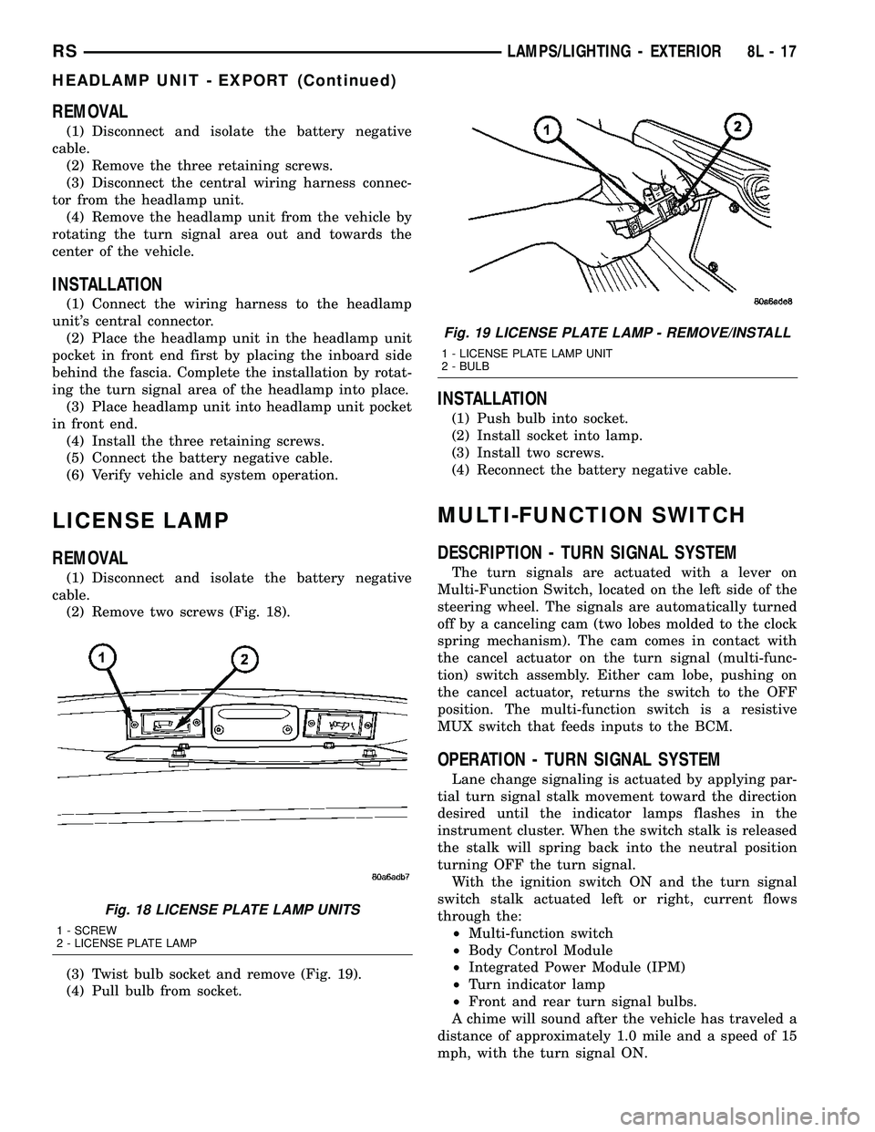
LICENSE LAMP
REMOVAL
(1) Disconnect and isolate the battery negative
cable.
(2) Remove two screws (Fig. 18).
(3) Twist bulb socket and remove (Fig. 19).
(4) Pull bulb from socket.
INSTALLATION
(1) Push bulb into socket.
(2) Install socket into lamp.
(3) Install two screws.
(4) Reconnect the battery negative cable.
MULTI-FUNCTION SWITCH
DESCRIPTION - TURN SIGNAL SYSTEM
The turn signals are actuated with a lever on
Multi-Function Switch, located on the left side of the
steering wheel. The signals are automatically turned
off by a canceling cam (two lobes molded to the clock
spring mechanism). The cam comes in contact with
the cancel actuator on the turn signal (multi-func-
tion) switch assembly. Either cam lobe, pushing on
the cancel actuator, returns the switch to the OFF
position. The multi-function switch is a resistive
MUX switch that feeds inputs to the BCM.
OPERATION - TURN SIGNAL SYSTEM
Lane change signaling is actuated by applying par-
tial turn signal stalk movement toward the direction
desired until the indicator lamps flashes in the
instrument cluster. When the switch stalk is released
the stalk will spring back into the neutral position
turning OFF the turn signal.
With the ignition switch ON and the turn signal
switch stalk actuated left or right, current flows
through the:
²Multi-function switch
²Body Control Module
²Integrated Power Module (IPM)
²Turn indicator lamp
²Front and rear turn signal bulbs.
A chime will sound after the vehicle has traveled a
distance of approximately 1.0 mile and a speed of 15
mph, with the turn signal ON.
Fig. 18 LICENSE PLATE LAMP UNITS
1 - SCREW
2 - LICENSE PLATE LAMP
Fig. 19 LICENSE PLATE LAMP - REMOVE/INSTALL
1 - LICENSE PLATE LAMP UNIT
2 - BULB
RSLAMPS/LIGHTING - EXTERIOR8L-17
HEADLAMP UNIT - EXPORT (Continued)
Page 425 of 2339
POWER LIFTGATE SYSTEM
DESCRIPTION
the components of the power liftgate system are:
²Liftgate gear motor assembly
²Latch assembly
²Lift gear and rod
²Power liftgate control module
²Chime/thermistor
²Full open switch
²Engage actuator
²Pinch sensor
²Liftgate handle switch
²Overhead console switch
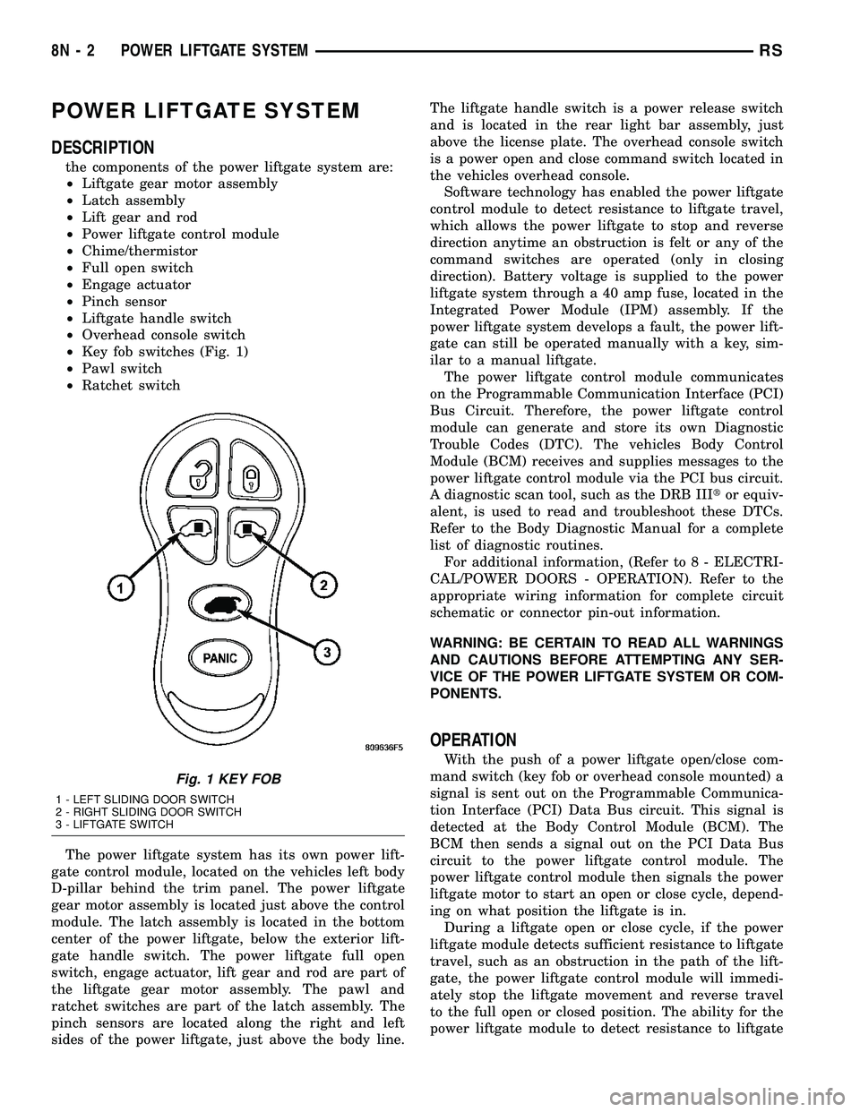
²Key fob switches (Fig. 1)
²Pawl switch
²Ratchet switch
The power liftgate system has its own power lift-
gate control module, located on the vehicles left body
D-pillar behind the trim panel. The power liftgate
gear motor assembly is located just above the control
module. The latch assembly is located in the bottom
center of the power liftgate, below the exterior lift-
gate handle switch. The power liftgate full open
switch, engage actuator, lift gear and rod are part of
the liftgate gear motor assembly. The pawl and
ratchet switches are part of the latch assembly. The
pinch sensors are located along the right and left
sides of the power liftgate, just above the body line.The liftgate handle switch is a power release switch
and is located in the rear light bar assembly, just
above the license plate. The overhead console switch
is a power open and close command switch located in
the vehicles overhead console.
Software technology has enabled the power liftgate
control module to detect resistance to liftgate travel,
which allows the power liftgate to stop and reverse
direction anytime an obstruction is felt or any of the
command switches are operated (only in closing
direction). Battery voltage is supplied to the power
liftgate system through a 40 amp fuse, located in the
Integrated Power Module (IPM) assembly. If the
power liftgate system develops a fault, the power lift-
gate can still be operated manually with a key, sim-
ilar to a manual liftgate.
The power liftgate control module communicates
on the Programmable Communication Interface (PCI)
Bus Circuit. Therefore, the power liftgate control
module can generate and store its own Diagnostic
Trouble Codes (DTC). The vehicles Body Control
Module (BCM) receives and supplies messages to the
power liftgate control module via the PCI bus circuit.
A diagnostic scan tool, such as the DRB IIItor equiv-
alent, is used to read and troubleshoot these DTCs.
Refer to the Body Diagnostic Manual for a complete
list of diagnostic routines.
For additional information, (Refer to 8 - ELECTRI-
CAL/POWER DOORS - OPERATION). Refer to the
appropriate wiring information for complete circuit
schematic or connector pin-out information.
WARNING: BE CERTAIN TO READ ALL WARNINGS
AND CAUTIONS BEFORE ATTEMPTING ANY SER-
VICE OF THE POWER LIFTGATE SYSTEM OR COM-
PONENTS.
OPERATION
With the push of a power liftgate open/close com-
mand switch (key fob or overhead console mounted) a
signal is sent out on the Programmable Communica-
tion Interface (PCI) Data Bus circuit. This signal is
detected at the Body Control Module (BCM). The
BCM then sends a signal out on the PCI Data Bus
circuit to the power liftgate control module. The
power liftgate control module then signals the power
liftgate motor to start an open or close cycle, depend-
ing on what position the liftgate is in.
During a liftgate open or close cycle, if the power
liftgate module detects sufficient resistance to liftgate
travel, such as an obstruction in the path of the lift-
gate, the power liftgate control module will immedi-
ately stop the liftgate movement and reverse travel
to the full open or closed position. The ability for the
power liftgate module to detect resistance to liftgate
Fig. 1 KEY FOB
1 - LEFT SLIDING DOOR SWITCH
2 - RIGHT SLIDING DOOR SWITCH
3 - LIFTGATE SWITCH
8N - 2 POWER LIFTGATE SYSTEMRS
Page 443 of 2339
POWER LOCKS
TABLE OF CONTENTS
page page
POWER LOCKS
DESCRIPTION.........................20
OPERATION...........................21
DOOR CYLINDER LOCK SWITCH - EXPORT
DESCRIPTION.........................22
OPERATION...........................22
DIAGNOSIS AND TESTING
DOOR CYLINDER LOCK SWITCH -
EXPORT............................22
REMOVAL.............................22
INSTALLATION.........................22
DOOR LOCK MOTOR
DIAGNOSIS AND TESTING
DOOR LOCK MOTOR..................23
DOOR LOCK SWITCH
DIAGNOSIS AND TESTING
DOOR LOCK SWITCH..................23
REMOVAL.............................23INSTALLATION.........................23
KEYLESS ENTRY TRANSMITTER
DIAGNOSIS AND TESTING
KEYLESS ENTRY TRANSMITTER.........24
STANDARD PROCEDURE
STANDARD PROCEDURE - HORN CHIRP
PREFERENCE........................24
STANDARD PROCEDURE - BATTERY
REPLACEMENT.......................24
STANDARD PROCEDURE - REMOTE
KEYLESS ENTRY TRANSMITTER
PROGRAMMING......................24
SPECIFICATIONS
SPECIFICATIONS - TRANSMITTER RANGE . 24
SPECIFICATIONS - BATTERY............24
SLIDING DOOR LOCK MOTOR
REMOVAL.............................25
INSTALLATION.........................25
POWER LOCKS
DESCRIPTION
POWER LOCKS
The power lock system allows all of the doors to be
locked or unlocked electrically by operating a switch
on either front door trim panel. The power lock sys-
tem receives non-switched battery current through a
fuse in the Integrated Power Module (IPM), so that
the power locks remain operational, regardless of the
ignition switch position.
The Body Control Module (BCM) locks the doors
automatically when the vehicle is driven beyond the
speed of 25.7 Km/h (15 mph), all doors are closed, the
accelerator pedal is depressed and the door lock actu-
ation had not been previously activated. The rolling
door lock feature is customer programmable.
This vehicle also offers several customer program-
mable features, which allows the selection of several
optional electronic features to suit individual prefer-
ences.
The power lock system for this vehicle can also be
operated remotely using the available Remote Key-
less Entry (RKE) system radio frequency transmit-
ters, if equipped.
AUTOMATIC DOOR LOCKS
When enabled, this feature will lock all of the door
locks if all of the doors are closed and the vehicle
speed goes above 25.7 km/h (15 mph). If a door
unlock has occurred, then the BCM will perform
another auto lock, if the doors did not electrically
unlock, another auto lock will not occur.
DOOR LOCK INHIBIT
When the key is in the ignition (in any switch posi-
tion) and either front door is opened, the door lock
switches LOCK functions are disabled. The
UN-LOCK functions are still functional. This protects
against locking the vehicle with the key still in the
ignition. The RKE key fob will still lock the doors.
After the key is removed from the ignition or the
doors are closed, the power door locks will operate
normally.
REMOTE KEYLESS ENTRY
The Remote Keyless Entry (RKE) system allows
the use of a remote battery-powered radio transmit-
ter to communicate with the BCM to actuate the
power lock system.
The RKE transmitters are also equipped with a
Panic button. If the Panic button on the RKE trans-
mitter is depressed, the horn will sound and the
exterior lights will flash on the vehicle for about
three minutes, or until the Panic button is depressed
8N - 20 POWER LOCKSRS
Page 444 of 2339
a second time. Pressing the Panic button also acti-
vates the courtesy lamps. Pressing the Panic button
again stops the exterior lamps from flashing and the
horn from sounding. However, the courtesy lamps
will remain illuminated until either the BCM times
out lamp operation or until the turning of the igni-
tion. The panic feature will operate if the ignition is
ON, but only if the Panic button is pressed prior to
starting the vehicle. A vehicle speed of about 25.7
km/h (15 miles-per-hour) will also cancel the panic
event.
The RKE system can also perform other functions
on this vehicle. If the vehicle is equipped with the
optional Vehicle Theft Security System (VTSS), the
RKE transmitter will arm the VTSS when the Lock
button is depressed, and disarm the VTSS when the
Unlock button is depressed.
The RKE system includes two transmitters when
the vehicle is shipped from the factory, but the sys-
tem can retain the vehicle access codes of up to a
total of eight transmitters. If an RKE transmitter is
inoperative or lost, new transmitter vehicle access
codes can be programmed into the system using a
DRB IIItscan tool.
This vehicle also offers several customer program-
mable features, which allows the selection of several
optional electronic features to suit individual prefer-
ences. Customer programmable feature options
affecting the RKE system include:
²Automatic Door Lock- Customer programma-
ble feature that allows the BCM to perform an auto-
matic door lock if the vehicle speed is above 25.7
km/h (15 miles-per-hour).
²Automatic Door Unlock On Exit- Customer
programmable feature that allows the BCM to per-
form an automatic door unlock if the vehicle speed is
0, vehicle in park and driver door is opened.
²Flash Lights with Lock and Unlock- Allows
the option of having the park lamps flash as an opti-
cal verification that the RKE system received a valid
Lock request or Unlock request from the RKE trans-
mitter, or having no optical verification.
²Programming Additional Transmitters-
Allows up to a total of four transmitter vehicle access
codes to be stored.
²Remote Unlock Sequence- Allows the option
of having only the driver side front door unlock when
the RKE transmitter Unlock button is depressed the
first time. The remaining doors unlock when the but-
ton is depressed a second time within 5 seconds of
the first unlock press. Another option is having all
doors unlock upon the first depression of the RKE
transmitter Unlock button.
²Sound Horn on Lock- Allows the option of
having the horn sound a short chirp as an audible
verification that the RKE system received a validLock request from the RKE transmitter, or having no
audible verification.
OPERATION
POWER LOCKS
The Body Control Module (BCM) locks or unlocks
the doors when an actuation input signal from a door
lock switch, Central Lock key cylinder or Remote
Keyless Entry (RKE) is received. The BCM turns on
the output drivers and provides a voltage level to the
door lock motor for a specified time.
REMOTE KEYLESS ENTRY
The RKE transmitter uses radio frequency signals
to communicate with the SKREEM module. The
SKREEM is on the PCI bus. When the operator
presses a button on the transmitter, it sends a spe-
cific request to the SKREEM. In turn, the SKREEM
sends the appropriate request over the PCI bus to
the following:
²Integrated Power Module (IPM)- to activate
the park lamps, the headlamps and the horn for the
horn chirp.
²Power Liftgate Module (PLGM)- to control
the liftgate lock and unlock functions.
After pressing the lock button on the RKE trans-
mitter, all of the door locks will lock, the illuminated
entry will turn off (if all doors are closed) and the
vehicle theft security system (if equipped) will arm.
Pressing the unlock button one time will unlock
the driver door, or all doors based on the customer
programmable feature enabled, the illuminated entry
will turn on the courtesy lamps and the vehicle theft
security system (if equipped) will disarm. Pressing
the unlock button a second time, the remaining door
locks will unlock.
If the vehicle is equipped with the memory system,
the memory message will identify which transmitter
(1 or 2) sent the signal.
ROLLING CODE
The rolling code feature changes part of the trans-
mitter message each time that it is used. The trans-
mitter message and the receiver message increment
together. Under certain conditions with a rolling code
system, such as pressing a button on the RKE trans-
mitter over 255 times outside of receiver range or
replacing the battery, the receiver and transmitter
can fall out of synchronization. To re-synchronize,
press and release the UNLOCK button on the RKE
transmitter repeatedly (it may take up to eight
cycles) while listening carefully for the power door
locks in the vehicle to cycle, indicating that resyn-
chronization has occurred.
RSPOWER LOCKS8N-21
POWER LOCKS (Continued)
Page 451 of 2339
AUTOMATIC DAY / NIGHT
MIRROR
DESCRIPTION
An automatic dimming inside day/night rear view
mirror and an automatic dimming driver side outside
rear view mirror are available factory-installed
options on this model. Following is a general descrip-
tion of this optional equipment.
The automatic day/night mirror is able to automat-
ically change its reflectance. A thin layer of electro-
chromic material between two pieces of conductive
glass make up the face of the mirror. Two photocell
sensors are used to monitor light levels and adjust
the reflectance of the mirror to reduce the glare of
headlamps approaching the vehicle from the rear.
For removal procedures, (Refer to 23 - BODY/IN-
TERIOR/REAR VIEW MIRROR - REMOVAL).
OPERATION
The ambient photocell sensor faces forward, to
detect the outside light levels. A second sensor faces
rearward to detect the light level received through
the vehicles back window. When the difference
between the two light levels becomes too great (the
light level received at the rear of the mirror is much
higher than that at the front of the mirror), the mir-
ror begins to darken.
The mirror switch allows the driver a manual con-
trol of whether the automatic dimming feature is
operational. When AUTO is selected a small Light-
Emitting Diode (LED), to the right of the mirror
switch, is illuminated. The automatic dimming fea-
ture will only operate when the ignition switch is in
the On position. The mirror also senses the backup
lamp circuit, and will automatically disable its self-
dimming feature whenever the transmission gear
selector is in the Reverse position.
NOTE: The mirror always defaults to an ON state
upon ignition.
The driver side automatic dimming mirror is stan-
dard with the automatic dimming inside mirror. The
signal to control the dimming of that mirror is gen-
erated by the automatic day/night inside rear view
mirror circuitry. That signal is then delivered to the
driver side outside rear view mirror on a hard wired
circuit.
The automatic day/night mirror cannot be
repaired. If faulty or damaged, the entire inside rear
view mirror assembly must be replaced.
DIAGNOSIS AND TESTING
AUTOMATIC DAY / NIGHT MIRROR
For circuit descriptions and diagrams, refer to the
appropriate wiring information. The wiring informa-
tion includes wiring diagrams, proper wire and con-
nector repair procedures, details of wire harness
routing and retention, connector pin-out information
and location views for the various wire harness con-
nectors, splices and grounds.
(1) Check the fuse in the intelligent power module.
If OK, go to Step 2. If not OK, repair the shorted cir-
cuit or component as required and replace the faulty
fuse.
(2) Turn the ignition switch to the On position.
Check for battery voltage at the fuse in the intelli-
gent power module. If OK, go to Step 3. If not OK,
repair the open circuit to the ignition switch as
required.
(3) Unplug the wire harness connector from the
automatic day/night mirror. Check for battery voltage
at the fused ignition switch output circuit cavity of
the automatic day/night mirror wire harness connec-
tor. If OK, go to Step 4. If not OK, repair the open
circuit to the junction block as required.
(4) Turn the ignition switch to the Off position.
Check for continuity between the ground circuit cav-
ity of the automatic day/night mirror wire harness
connector and a good ground. There should be conti-
nuity. If OK, go to Step 5. If not OK, repair the cir-
cuit to ground as required.
(5) Turn the ignition switch to the On position. Set
the parking brake. Place the transmission gear selec-
tor lever in the Reverse position. Check for battery
voltage at the backup lamp switch output circuit cav-
ity of the automatic day/night mirror wire harness
connector. If voltage is present, reinstall the auto-
matic day/night mirror wire harness connector and
go to Step 6. If not OK, repair the open circuit as
required.
(6) Place the transmission gear selector lever in
the Neutral position. Place the automatic day/night
mirror switch in the On (LED in the switch is
lighted) position. Cover the forward facing ambient
photocell sensor to keep out any ambient light.
NOTE: The ambient photocell sensor must be cov-
ered completely, so that no light reaches the sen-
sor. Use a finger pressed tightly against the sensor,
or cover the sensor completely with electrical tape.
(7) Shine a light into the rearward facing head-
lamp photocell sensor. The automatic day/night mir-
ror should darken. The automatic day/night mirror
should darken within 2 minutes if testing for the
first time. For immediate response, turn the vehicle
8N - 28 POWER MIRRORSRS
Page 454 of 2339

POWER SEAT SYSTEM
TABLE OF CONTENTS
page page
POWER SEAT SYSTEM
DESCRIPTION
POWER SEAT SYSTEM................31
MEMORY SYSTEM....................32
OPERATION
POWER SEAT SYSTEM................32
MEMORY SYSTEM....................33
DIAGNOSIS AND TESTING
POWER SEAT SYSTEM................33
MEMORY SYSTEM....................33
SEAT SWITCH
DESCRIPTION.........................34
OPERATION...........................34
DIAGNOSIS AND TESTING
DRIVER SEAT SWITCH.................34
REMOVAL.............................36INSTALLATION.........................36
MEMORY SWITCH
DESCRIPTION.........................36
OPERATION...........................36
DIAGNOSIS AND TESTING
MEMORY SWITCH....................37
REMOVAL.............................37
INSTALLATION.........................37
POWER SEAT TRACK
DESCRIPTION.........................37
OPERATION...........................38
DIAGNOSIS AND TESTING
POWER SEAT TRACK..................38
REMOVAL.............................38
INSTALLATION.........................39
POWER SEAT SYSTEM
DESCRIPTION
POWER SEAT SYSTEM
The power seat system option allows the driver
and front seat passenger to electrically adjust their
seating positions for optimum control and comfort.
The driver side power front seat can be adjusted in
eight different directions: up, down, front up, front
down, rear up, rear down, forward, rearward and
recliner forward and rearward. The passenger side
power front seat can be adjusted in four different
directions: forward, rearward and recliner forward
and rearward.
The power seat system receives battery current
through a 40 amp fuse in the Integrated Power Mod-
ule (IPM) and a 30 amp circuit breaker under the
seat so that the power seats remain operational,
regardless of the ignition switch position.
WARNING: SOME VEHICLES ARE EQUIPPED WITH
SEATBACK MOUNTED AIRBAGS (Fig. 1). BEFORE
ATTEMPTING TO DIAGNOSE OR SERVICE ANY
SEAT OR POWER SEAT SYSTEM COMPONENT
YOU MUST FIRST DISCONNECT AND ISOLATE THE
BATTERY NEGATIVE CABLE. THEN WAIT TWO MIN-
UTES FOR THE SYSTEM CAPACITOR TO DIS-
CHARGE BEFORE FURTHER SYSTEM SERVICE.
THIS IS THE ONLY SURE WAY TO DISABLE THE
AIRBAG SYSTEM. FAILURE TO DO SO COULDRESULT IN ACCIDENTAL AIRBAG DEPLOYMENT
AND POSSIBLE PERSONAL INJURY.
The eight-way driver side power seat is also avail-
able with the heated seat and/or memory seat sys-
tem. The memory seat system automatically
positions the power seat for two different drivers.
Fig. 1 IDENTIFYING A SIDE AIRBAG EQUIPPED
SEAT
1 - AIRBAG LABEL
RSPOWER SEAT SYSTEM8N-31
Page 455 of 2339
(Refer to 8 - ELECTRICAL/HEATED SEATS -
DESCRIPTION) for more information on the heated
seat option. (Refer to 8 - ELECTRICAL/POWER
SEATS - DESCRIPTION - MEMORY SEAT SYS-
TEM) for more information on the memory seat sys-
tem.
The power seat system includes the following com-
ponents:
²Power seat recliners
²Power seat switches
²Power seat tracks
²Circuit breaker
The power seat system with memory and heated
seat options includes the following components:
²Power seat recliner
²Power seat switch
²Power seat track.
²Memory Seat Mirror Module (MSMM)
²Memory set switch
²Heated Seat Module (HSM)
²Heated seat switch
²Electronic Vehicle Information Center (EVIC)
MEMORY SYSTEM
The memory system is able to store and recall the
driver side power seat positions (including the power
recliner position), power adjustable pedal positions
and the driver outside mirror position for two driv-
ers. On vehicles equipped with a factory radio, the
memory system is also able to store and recall radio
station presets for two drivers. The memory system
also will store and recall the last station listened to
for each driver, even if it is not one of the preset sta-
tions.
The memory system will automatically return to
its preset settings when the corresponding numbered
button of the memory switch is depressed, or when
the doors are unlocked using the corresponding
Remote Keyless Entry (RKE) transmitter. A customer
programmable feature of the memory system allows
the RKE recall of memory features to be disabled, if
desired. This programmable feature is internal in the
Electronic Vehicle Information Center (EVIC) mod-
ule, which is located in the overhead console.
A Memory Seat Mirror Module (MSMM) is used to
control and integrate the many electronic functions
and features included in the memory seat and mirror
systems.
The memory system includes the following compo-
nents:
²Memory Seat Mirror Module (MSMM)
²Memory set switch
²Position potentiometers on the driver outside
side view mirror
²Position potentiometers on the power adjustable
pedal motor²Position potentiometers on the driver side power
seat track and power seat recliner motors
²Electronic Vehicle Information Center (EVIC)
²Radio receiver (if PCI data bus capable)
Certain functions of the memory system rely upon
resources shared with other electronic modules in the
vehicle over the Programmable Communications
Interface (PCI) data bus network. Initial diagnosis of
these electronic modules or the PCI data bus network
requires the use of a DRBIIItor equivalent scan tool
and the proper Diagnostic Procedures information. If
this method does not prove conclusive, the proper
wiring schematics and the service manual diagnostic
information are required.
The other electronic modules that may affect mem-
ory system operation are:
²Body Control Module (BCM)- (Refer to 8 -
ELECTRICAL/ELECTRONIC CONTROL MOD-
ULES/BODY CONTROL/CENTRAL TIMER MODUL
- DESCRIPTION) for additional information.
²Powertrain Control Module (PCM)- (Refer
to 8 - ELECTRICAL/ELECTRONIC CONTROL
MODULES/POWERTRAIN CONTROL MODULE -
DESCRIPTION) for additional information.
²Transmission Control Module (TCM)- (Refer
to 8 - ELECTRICAL/ELECTRONIC CONTROL
MODULES/TRANSMISSION CONTROL MODULE -
DESCRIPTION) for additional information.
(Refer to 8 - ELECTRICAL/HEATED SEATS -
DESCRIPTION) for additional information on the
heated seat system. (Refer to 8 - ELECTRICAL/
POWER LOCKS - DESCRIPTION) for additional
information on the RKE system.
OPERATION
POWER SEAT SYSTEM
The power seat system receives battery current
through fuse #22 in the Integrated Power Module
(IPM) and a circuit breaker under the front seats,
regardless of the ignition switch position.
When a power seat switch control knob or knobs
are actuated, a battery feed and a ground path are
applied through the switch contacts to the appropri-
ate power seat track adjuster motor. The selected
adjuster motor operates to move the seat track
through its drive unit in the selected direction until
the switch is released, or until the travel limit of the
seat track is reached. When the switch is moved in
the opposite direction, the battery feed and ground
path to the motor are reversed through the switch
contacts. This causes the adjuster motor to run in the
opposite direction.
No power seat switch should be held applied in any
direction after the seat track has reached its travel
limit. The power seat adjuster motor each contain a
8N - 32 POWER SEAT SYSTEMRS
POWER SEAT SYSTEM (Continued)
Page 456 of 2339
self-resetting circuit breaker to protect them from
overload. However, consecutive or frequent resetting
of the circuit breaker must not be allowed to con-
tinue, or the motor may be damaged.
MEMORY SYSTEM
The Memory Seat Mirror Module (MSMM) receives
battery current through fuse #22 in the Integrated
Power Module (IPM) and the power seat system cir-
cuit breaker, located under the driver side front seat
near the rear edge of the seat cushion pan. The mem-
ory system does not operate with the Ignition-Off
Draw (IOD) fuse removed. The MSMM will drive a
maximum of 2 motors at a time in a given direction.
If conflicting directions are requested, the priority for
response will be approximately as follows:
²Seat Track Rearward or Forward
²Seat Front Down or Up
²Seat Rear Down or Up
²Recliner Rearward or Forward
The inputs from these switches to the MSMM is a
current limited battery source fed by the MSMM.
This protects the MSMM printed circuit board traces
from acting as fuses. All of these switch contact
inputs to the MSMM are normally closed to ground,
except when actuated.
For diagnosis of the MSMM, the Programmable
Communication Interface (PCI) data bus, or the other
electronic modules on the PCI data bus that provide
inputs and outputs for the memory system, the use of
a DRBIIItor equivalent scan tool and the proper
Diagnostic Procedures information is recommended.
ELECTRONIC VEHICLE INFORMATION CENTER
The Electronic Vehicle Information Center (EVIC)
serves as the user interface for the memory system.
It displays memory system status messages and pro-
vides the user with the means for enabling and dis-
abling the many customer programmable features
available on the vehicle, including those for the mem-
ory system.
(Refer to 8 - ELECTRICAL/OVERHEAD CON-
SOLE/ELECTRONIC VEHICLE INFO CENTER -
DESCRIPTION) for additional information on the
EVIC.
DIAGNOSIS AND TESTING
POWER SEAT SYSTEM
Following are tests that will help to diagnose the
hard wired components and circuits of the power seat
system. However, if the vehicle is also equipped with
the optional memory system, these tests may not
prove conclusive in the diagnosis of the driver side
power seat. In order to obtain conclusive testing ofthe driver side power seat with the memory system
option, the Programmable Communications Interface
(PCI) data bus network and all of the electronic mod-
ules that provide inputs to, or receive outputs from
the memory system components must be checked,
(Refer to 8 - ELECTRICAL/POWER SEATS - DIAG-
NOSIS AND TESTING).
WARNING: SOME VEHICLES ARE EQUIPPED WITH
SEATBACK MOUNTED AIRBAGS. BEFORE
ATTEMPTING TO DIAGNOSE OR SERVICE ANY
SEAT OR POWER SEAT SYSTEM COMPONENT
YOU MUST FIRST DISCONNECT AND ISOLATE THE
BATTERY NEGATIVE CABLE. THEN WAIT TWO MIN-
UTES FOR THE SYSTEM CAPACITOR TO DIS-
CHARGE BEFORE FURTHER SYSTEM SERVICE.
THIS IS THE ONLY SURE WAY TO DISABLE THE
AIRBAG SYSTEM. FAILURE TO DO SO COULD
RESULT IN ACCIDENTAL AIRBAG DEPLOYMENT
AND POSSIBLE PERSONAL INJURY.
(1) If either power seat is completely inoperable,
check the power seat circuit breaker, located under
the trailing edge of the driver side power seat. If the
power seat circuit breaker is OK, continue to the
next step.
(2) Check for proper battery and ground connec-
tions at the power seat switch and/or memory seat
module. Repair any wiring as necessary.
(3) Check the power seat system wire harness con-
nections and pins to ensure proper circuit continuity
and ground paths.
MEMORY SYSTEM
In order to obtain conclusive testing of the memory
system, the Programmable Communications Interface
(PCI) data bus network and all of the electronic mod-
ules that provide inputs to, or receive outputs from
the memory system components must be checked.
The most reliable, efficient, and accurate means to
diagnose the driver side power seat with the memory
system option requires the use of a DRBIIItor
equivalent scan tool and the proper Diagnostic Proce-
dures information. The DRBIIItscan tool can pro-
vide confirmation that the PCI data bus is functional,
that all of the electronic modules are sending and
receiving the proper messages on the PCI data bus,
and that the memory system is receiving the proper
hard wired inputs and relaying the proper hard
wired outputs to perform its driver side power seat
functions.
(1) If the driver power seat exhibits an interrupted
or jerky motion, ensure the wire harness is connected
correctly. To verify the concern, obtain a DRB IIItor
equivalent scan tool and energize each axis one at a
time. If any axis stops in approximately 2 seconds
(without hitting the end of travel), the feedback for
RSPOWER SEAT SYSTEM8N-33
POWER SEAT SYSTEM (Continued)
Page 461 of 2339
upper half of the track unit. Each motor moves the
seat adjuster through a combination of worm-drive
gearboxes and screw-type drive units. The horizontal
adjustment motor moves the seat track in the for-
ward and aft directions. The recliner adjustment
motor moves the seat back in the forward and rear-
ward directions.
The power seat track unit cannot be repaired, and
is serviced only as a complete unit. If any component
in this unit is faulty or damaged, the entire power
seat track unit must be replaced.
OPERATION
When the power seat switch control knob or knobs
are actuated, a battery feed and a ground path are
applied through the switch contacts to the power seat
track or recliner adjuster motor. The selected
adjuster motor operates to move the seat track or
recliner through its drive unit in the selected direc-
tion until the switch is released, or until the travel
limit of the adjuster is reached. When the switch is
moved in the opposite direction, the battery feed and
ground path to the motor are reversed through the
switch contacts. This causes the adjuster motor to
run in the opposite direction.
No power seat switch should be held applied in any
direction after the adjuster has reached its travel
limit. The power seat adjuster motors each contain a
self-resetting circuit breaker to protect them from
overload. However, consecutive or frequent resetting
of the circuit breaker must not be allowed to con-
tinue, or the motor may be damaged.
DIAGNOSIS AND TESTING
POWER SEAT TRACK
WARNING: SOME VEHICLES ARE EQUIPPED WITH
SEATBACK MOUNTED AIRBAGS. BEFORE
ATTEMPTING TO DIAGNOSE OR SERVICE ANY
SEAT OR POWER SEAT SYSTEM COMPONENT
YOU MUST FIRST DISCONNECT AND ISOLATE THE
BATTERY NEGATIVE CABLE. THEN WAIT TWO MIN-
UTES FOR THE SYSTEM CAPACITOR TO DIS-
CHARGE BEFORE FURTHER SYSTEM SERVICE.
THIS IS THE ONLY SURE WAY TO DISABLE THE
AIRBAG SYSTEM. FAILURE TO DO SO COULD
RESULT IN ACCIDENTAL AIRBAG DEPLOYMENT
AND POSSIBLE PERSONAL INJURY.
Actuate the power seat switch to move the power
seat track adjusters in each direction. The power seat
track adjusters should move in each of the selected
directions. If a power seat track adjuster operates in
one direction only, move the adjuster a short distance
in the opposite direction and test again to be certainthat the adjuster is not at its travel limit. If the
power seat track adjuster still operates in one direc-
tion only, (Refer to 8 - ELECTRICAL/POWER
SEATS/DRIVER SEAT SWITCH - DIAGNOSIS AND
TESTING). If the power seat track adjuster does not
operate in more than one direction, perform the fol-
lowing tests.
TESTING POWER SEAT TRACK MOTORS
(1) Check the power seat circuit breaker under the
seat. If OK, go to Step 2. If not OK, replace the
faulty power seat circuit breaker.
(2) Check for battery voltage at the power seat cir-
cuit breaker under the seat. If OK, go to Step 3. If
not OK, repair the open fused B(+) circuit to the fuse
in the Integrated Power Module (IPM) as required.
(3) Remove the outboard seat cushion side cover,
(Refer to 23 - BODY/SEATS/SEAT CUSHION SIDE
COVERS - REMOVAL). Disconnect the wire harness
connector from the power seat switch. Check for bat-
tery voltage at the fused B(+) circuit cavity of the
power seat switch wire harness connector. If OK, go
to Step 4. If not OK, repair the open fused B(+) cir-
cuit to the power seat circuit breaker under the seat
as required.
(4) Check for continuity between the ground cir-
cuit cavity of the power seat switch wire harness con-
nector and a known good ground. There should be
continuity. If OK, go to Step 5. If not OK, repair the
open ground circuit as required.
(5) Test the power seat switch, (Refer to 8 - ELEC-
TRICAL/POWER SEATS/DRIVER SEAT SWITCH -
DIAGNOSIS AND TESTING). If the switch tests OK,
test the circuits of the power seat wire harness
between the inoperative power seat track adjuster
motor and the power seat switch for shorts or opens.
If the circuits check OK, replace the faulty power
seat track unit. If the circuits are not OK, repair the
power seat wire harness as required.
REMOVAL
WARNING: SOME VEHICLES ARE EQUIPPED WITH
SEATBACK MOUNTED AIRBAGS. BEFORE
ATTEMPTING TO DIAGNOSE OR SERVICE ANY
SEAT OR POWER SEAT SYSTEM COMPONENT
YOU MUST FIRST DISCONNECT AND ISOLATE THE
BATTERY NEGATIVE CABLE. THEN WAIT TWO MIN-
UTES FOR THE SYSTEM CAPACITOR TO DIS-
CHARGE BEFORE FURTHER SYSTEM SERVICE.
THIS IS THE ONLY SURE WAY TO DISABLE THE
AIRBAG SYSTEM. FAILURE TO DO SO COULD
RESULT IN ACCIDENTAL AIRBAG DEPLOYMENT
AND POSSIBLE PERSONAL INJURY.
(1) Disconnect and isolate the battery negative
cable.
8N - 38 POWER SEAT SYSTEMRS
POWER SEAT TRACK (Continued)