Servo CHRYSLER VOYAGER 2005 Service Manual
[x] Cancel search | Manufacturer: CHRYSLER, Model Year: 2005, Model line: VOYAGER, Model: CHRYSLER VOYAGER 2005Pages: 2339, PDF Size: 59.69 MB
Page 20 of 2339
FLUID FILL/CHECK
LOCATIONS
DESCRIPTION
The fluid check/fill point locations are located in
each applicable service manual section.
LUBRICATION POINTS
DESCRIPTION
Lubrication point locations are located in each
applicable Sections.
MAINTENANCE SCHEDULES
DESCRIPTION
DESCRIPTION
There are two maintenance schedules that show
therequiredservice for your vehicle.
First is ScheduleªBº. It is for vehicles that are
operated under the conditions that are listed below
and at the beginning of the schedule.
²Day or night temperatures are below 32É F (0É
C).
²Stop and go driving.
²Extensive engine idling.
²Driving in dusty conditions.
²Short trips of less than 10 miles (16 km).
²More than 50% of your driving is at sustained
high speeds during hot weather, above 90É F (32É C).
²Trailer towing.L
²Taxi, police, or delivery service (commercial ser-
vice).L
²Off-road or desert operation.
NOTE: Most vehicles are operated under the condi-
tions listed for Schedule(B(.
Second is ScheduleªAº. It is for vehicles that are
not operated under any of the conditions listed under
Schedule9B9.
Use the schedule that best describes your driving
conditions. Where time and mileage are listed, follow
the interval that occurs first.
CAUTION: Failure to perform the required mainte-
nance items may result in damage to the vehicle.
At Each Stop for Fuel
²Check the engine oil level about 5 minutes after
a fully warmed engine is shut off. Checking the oil
level while the vehicle is on level ground will
improve the accuracy of the oil level reading. Add oil
only when the level is at or below the ADD or MIN
mark.
²Check the windshield washer solvent and add if
required.
Once a Month
²Check tire pressure and look for unusual wear
or damage.
²Inspect the battery and clean and tighten the
terminals as required.
²Check the fluid levels of coolant reservoir, brake
master cylinder and transmission, add as needed.
²Check all lights and all other electrical items for
correct operation.
At Each Oil Change
²Change the engine oil filter.
²Inspect the exhaust system.
²Inspect the brake hoses.
²Inspect the CV joints and front suspension com-
ponents.
²Check the automatic transmission fluid level.
²Check the coolant level, hoses, and clamps.
SCHEDULE B
Follow schedule ªBº if you usually operate your
vehicle under one or more of the following conditions.
Change the automatic transmission fluid and filter
every 60,000 miles (96 000 km) if the vehicle is usu-
ally operated under one or more of the conditions
marked with anL.
²Day or night temperatures are below 32É F (0É
C).
²Stop and go driving.
²Extensive engine idling.
²Driving in dusty conditions.
²Short trips of less than 10 miles (16 km).
²More than 50% of your driving is at sustained
high speeds during hot weather, above 90É F (32É C).
²Trailer towing.L
²Taxi, police, or delivery service (commercial ser-
vice).L
²Off-road or desert operation.
RSLUBRICATION & MAINTENANCE0-7
Page 26 of 2339
DESCRIPTION - EXPORT
There are two maintenance schedules that show
therequiredservice for your vehicle.
First is ScheduleªAº. It is for vehicles that are not
operated under any of the conditions listed under
Schedule9B9.
Second is ScheduleªBº. It is for vehicles that are
operated under the conditions that are listed below
and at the beginning of the schedule.
²Day or night temperatures are below 0É C (32É
F).
²Stop and go driving.
²Extensive engine idling.
²Driving in dusty conditions.
²Short trips of less than 16 km (10 miles).
²More than 50% of your driving is at sustained
high speeds during hot weather, above 32É C (90É F).
²Trailer towing.L
²Taxi, police, or delivery service (commercial ser-
vice).L
²Off-road or desert operation.
NOTE: Most vehicles are operated under the condi-
tions listed for Schedule(B(.
Use the schedule that best describes your driving
conditions. Where time and mileage are listed, follow
the interval that occurs first.
CAUTION: Failure to perform the required mainte-
nance items may result in damage to the vehicle.
At Each Stop for Fuel
²Check the engine oil level about 5 minutes after
a fully warmed engine is shut off. Checking the oil
level while the vehicle is on level ground will
improve the accuracy of the oil level reading. Add oil
only when the level is at or below the ADD or MIN
mark.
²Check the windshield washer solvent and add if
required.
Once a Month
²Check tire pressure and look for unusual wear
or damage.
²Inspect the battery and clean and tighten the
terminals as required.
²Check the fluid levels of coolant reservoir, brake
master cylinder and transmission, add as needed.
²Check all lights and all other electrical items for
correct operation.
At Each Oil Change
²Change the engine oil filter.
²Inspect the exhaust system.
²Inspect the brake hoses.
²Inspect the CV joints and front suspension com-
ponents.
²Check the automatic transmission fluid level.
²Check the manual transmission fluid level.
²Check the coolant level, hoses, and clamps.
SCHEDULE A - EXPORT ONLY
Kilometers 12 000 24 000 36 000 48 000 60 000 72 000
(Miles) (7,500) (15,000) (22,500 (30,000) (37,500) (45,000)
[Months] [6] [12] [18] [24] [30] [36]
Change engine oil and engine
oil filter.XXXXX X
Rotate Tires XXXXX X
Inspect the brake linings. X X
Inspect the engine air cleaner
filter, replace if necessary. *XXX X X
Replace theengine air
cleaner filter.X
Replace thespark plugson
2.4 liter engines.X
Inspect the tie rod ends and
boot seals.X
Replace the air conditioning
filter.XX X
RSLUBRICATION & MAINTENANCE0-13
MAINTENANCE SCHEDULES (Continued)
Page 61 of 2339
DIAGNOSIS AND TESTING - STRUT ASSEMBLY
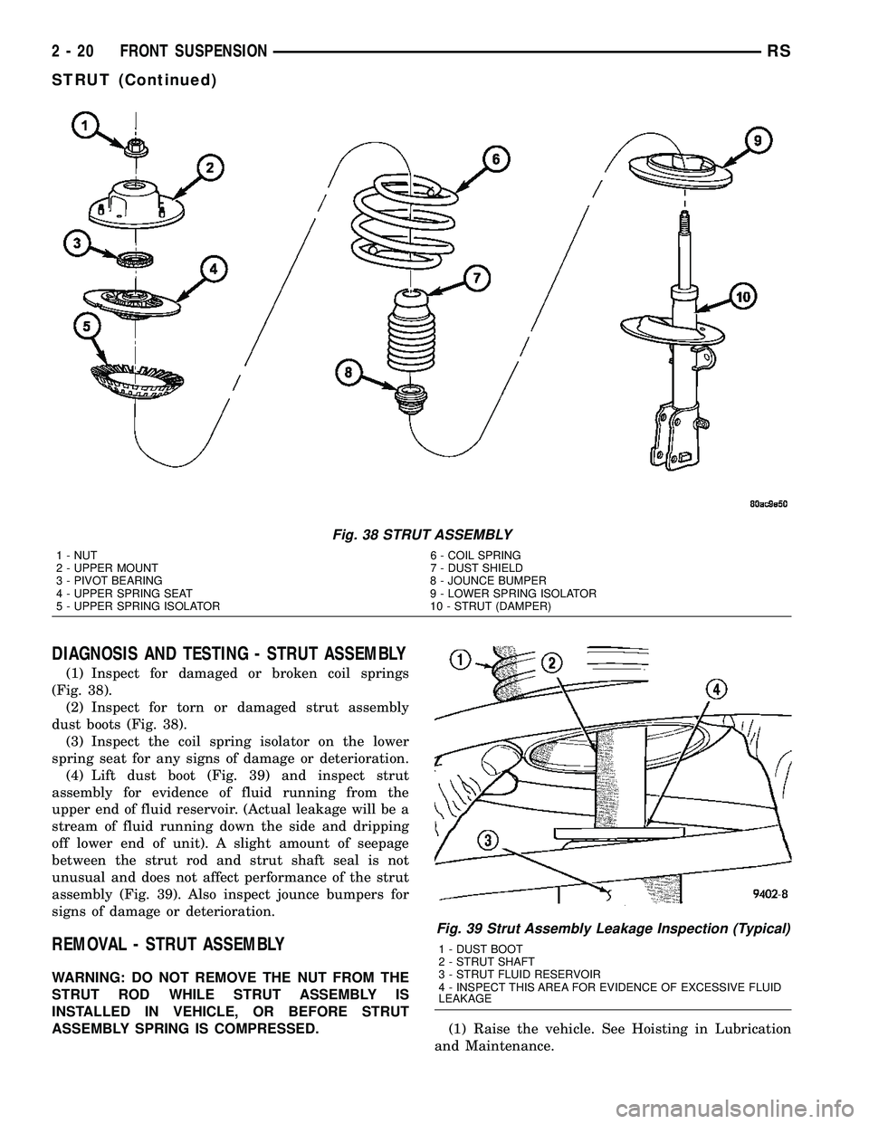
(1) Inspect for damaged or broken coil springs
(Fig. 38).
(2) Inspect for torn or damaged strut assembly
dust boots (Fig. 38).
(3) Inspect the coil spring isolator on the lower
spring seat for any signs of damage or deterioration.
(4) Lift dust boot (Fig. 39) and inspect strut
assembly for evidence of fluid running from the
upper end of fluid reservoir. (Actual leakage will be a
stream of fluid running down the side and dripping
off lower end of unit). A slight amount of seepage
between the strut rod and strut shaft seal is not
unusual and does not affect performance of the strut
assembly (Fig. 39). Also inspect jounce bumpers for
signs of damage or deterioration.
REMOVAL - STRUT ASSEMBLY
WARNING: DO NOT REMOVE THE NUT FROM THE
STRUT ROD WHILE STRUT ASSEMBLY IS
INSTALLED IN VEHICLE, OR BEFORE STRUT
ASSEMBLY SPRING IS COMPRESSED.
(1) Raise the vehicle. See Hoisting in Lubrication
and Maintenance.
Fig. 38 STRUT ASSEMBLY
1 - NUT 6 - COIL SPRING
2 - UPPER MOUNT 7 - DUST SHIELD
3 - PIVOT BEARING 8 - JOUNCE BUMPER
4 - UPPER SPRING SEAT 9 - LOWER SPRING ISOLATOR
5 - UPPER SPRING ISOLATOR 10 - STRUT (DAMPER)
Fig. 39 Strut Assembly Leakage Inspection (Typical)
1 - DUST BOOT
2 - STRUT SHAFT
3 - STRUT FLUID RESERVOIR
4 - INSPECT THIS AREA FOR EVIDENCE OF EXCESSIVE FLUID
LEAKAGE
2 - 20 FRONT SUSPENSIONRS
STRUT (Continued)
Page 93 of 2339
CONDITION POSSIBLE CAUSES CORRECTION
Lateral Pull 1. Unequal tire pressure 1. Inflate all tires to recommended
pressure
2. Radial tire lead 2. Perform lead correction procedure
3. Incorrect front wheel camber 3. Check and reset front wheel camber
4. Power steering gear imbalance 4. Replace power steering gear
5. Wheel braking 5. Correct braking condition causing
lateral pull
Excessive Steering Free
Play1. Incorrect Steering Gear Adjustment 1. Adjust Or Replace Steering Gear
2. Worn or loose tie rod ends 2. Replace or tighten tie rod ends
3. Loose steering gear mounting bolts 3. Tighten steering gear bolts to specified
torque
4. Loose or worn steering shaft coupler 4. Replace steering shaft coupler
Excessive Steering Effort 1. Low tire pressure 1. Inflate all tires to recommended
pressure
2. Lack of lubricant in steering gear 2. Replace steering gear
3. Low power steering fluid level 3. Fill power steering fluid reservoir to
correct level
4. Loose power steering pump drive
belt4. Correctly adjust power steering pump
drive belt
5. Lack of lubricant in ball joints 5. Lubricate or replace ball joints
6. Steering gear malfunction 6. Replace steering gear
7. Lack of lubricant in steering coupler 7. Replace steering coupler
STANDARD PROCEDURE
STANDARD PROCEDURE - WHEEL ALIGNMENT
PRE-WHEEL ALIGNMENT INSPECTION
Before any attempt is made to change or correct
the wheel alignment, the following inspection and
necessary corrections must be made to ensure proper
alignment.
(1) Verify that the fuel tank is full of fuel. If the
tank is not full, the reduction in weight will affect
the curb height of the vehicle and the alignment
angles.
(2) The passenger and luggage compartments of
the vehicle should be free of any load that is not fac-
tory equipment.
(3) Check the tires on the vehicle. All tires must be
the same size and in good condition with approxi-
mately the same amount of tread wear. Inflate all
the tires to the recommended air pressure.
(4) Check the front wheel and tire assemblies for
excessive radial runout.(5) Inspect lower ball joints and all steering link-
age for looseness, binding, wear or damage. Repair as
necessary.
(6) Check suspension fasteners for proper torque
and retighten as necessary.
(7) Inspect all suspension component rubber bush-
ings for signs of wear or deterioration. Replace any
faulty bushings or components before aligning the
vehicle.
(8) Check the vehicle's curb height to verify it is
within specifications. Refer to Curb Height Measure-
ment.
WHEEL ALIGNMENT SETUP
(1) Position the vehicle on an alignment rack.
(2) Install all required alignment equipment on
the vehicle per the alignment equipment manufactur-
er's instructions. On this vehicle, a four-wheel align-
ment is recommended.
2 - 52 WHEEL ALIGNMENTRS
WHEEL ALIGNMENT (Continued)
Page 113 of 2339

DISASSEMBLY - CALIPER PISTON AND
SEAL...............................24
CLEANING - CALIPER...................25
INSPECTION - CALIPER..................25
ASSEMBLY
ASSEMBLY - CALIPER GUIDE PIN
BUSHINGS (CONTINENTAL TEVES
BRAKES)............................25
ASSEMBLY - CALIPER PISTON AND SEAL . . 26
INSTALLATION
INSTALLATION - FRONT DISC BRAKE
CALIPER (CONTINENTAL TEVES
BRAKES)............................27
INSTALLATION - FRONT DISC BRAKE
CALIPER (TRW BRAKES)...............27
DISC BRAKE CALIPER - REAR
REMOVAL - REAR DISC BRAKE CALIPER....28
DISASSEMBLY - CALIPER PISTON AND SEAL..28
CLEANING - CALIPER...................29
INSPECTION - CALIPER..................29
ASSEMBLY - CALIPER PISTON AND SEAL . . . 30
INSTALLATION - REAR DISC BRAKE CALIPER..30
DISC BRAKE CALIPER ADAPTER
REMOVAL - FRONT DISC BRAKE CALIPER
ADAPTER...........................31
INSTALLATION - FRONT DISC BRAKE
CALIPER ADAPTER....................31
DISC BRAKE CALIPER GUIDE PINS
REMOVAL - DISC BRAKE CALIPER GUIDE
PINS (TRW BRAKES)..................31
INSTALLATION - DISC BRAKE CALIPER
GUIDE PINS (TRW BRAKES).............32
DRUM
REMOVAL.............................32
INSTALLATION.........................32
FLUID
DIAGNOSIS AND TESTING - BRAKE FLUID
CONTAMINATION.....................33
STANDARD PROCEDURE - BRAKE FLUID
LEVEL CHECKING.....................33
SPECIFICATIONS
BRAKE FLUID........................33
JUNCTION BLOCK
DESCRIPTION - NON-ABS JUNCTION BLOCK..33
OPERATION - NON-ABS JUNCTION BLOCK . . 33
REMOVAL - NON-ABS JUNCTION BLOCK....34
INSTALLATION - NON-ABS JUNCTION BLOCK..34
MASTER CYLINDER
DESCRIPTION
DESCRIPTION........................35
DESCRIPTION - RHD..................35
OPERATION...........................36
STANDARD PROCEDURE - MASTER
CYLINDER BLEEDING..................36
REMOVAL
REMOVAL - LHD......................36
REMOVAL - RHD......................37DISASSEMBLY - MASTER CYLINDER (FLUID
RESERVOIR).........................38
ASSEMBLY - MASTER CYLINDER (FLUID
RESERVOIR).........................39
INSTALLATION
INSTALLATION - LHD..................39
INSTALLATION - RHD..................39
PEDALS - ADJUSTABLE
REMOVAL.............................40
INSTALLATION.........................43
PEDAL TORQUE SHAFT - RHD
REMOVAL.............................44
INSTALLATION.........................44
POWER BRAKE BOOSTER
DESCRIPTION.........................45
OPERATION...........................46
DIAGNOSIS AND TESTING - POWER BRAKE
BOOSTER...........................46
REMOVAL
REMOVAL - LHD......................46
REMOVAL - RHD......................48
INSTALLATION
INSTALLATION - LHD..................50
INSTALLATION - RHD..................51
PROPORTIONING VALVE
DESCRIPTION - PROPORTIONING VALVE
(HEIGHT SENSING)....................53
OPERATION - PROPORTIONING VALVE
(HEIGHT SENSING)....................53
DIAGNOSIS AND TESTING -
PROPORTIONING VALVE (HEIGHT
SENSING)...........................54
REMOVAL - PROPORTIONING VALVE
(HEIGHT SENSING)....................55
INSTALLATION - PROPORTIONING VALVE
(HEIGHT SENSING)....................55
ROTOR
DIAGNOSIS AND TESTING - BRAKE ROTOR . . 55
STANDARD PROCEDURE - BRAKE ROTOR
MACHINING..........................58
REMOVAL - FRONT BRAKE ROTOR........59
INSTALLATION - FRONT BRAKE ROTOR.....59
SPECIFICATIONS
BRAKE ROTOR.......................60
BRAKE ROTOR - EXPORT..............60
SUPPORT PLATE - DRUM BRAKE
REMOVAL.............................61
INSTALLATION.........................61
WHEEL CYLINDERS
REMOVAL.............................62
INSPECTION..........................62
INSTALLATION.........................62
PARKING BRAKE
DESCRIPTION
DESCRIPTION........................62
DESCRIPTION - EXPORT...............63
OPERATION...........................63
5 - 2 BRAKES - BASERS
Page 115 of 2339
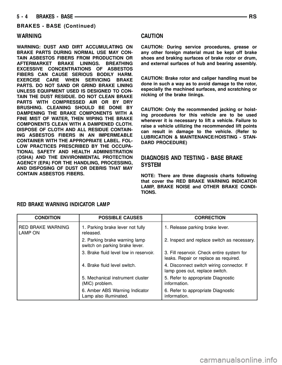
WARNING
WARNING: DUST AND DIRT ACCUMULATING ON
BRAKE PARTS DURING NORMAL USE MAY CON-
TAIN ASBESTOS FIBERS FROM PRODUCTION OR
AFTERMARKET BRAKE LININGS. BREATHING
EXCESSIVE CONCENTRATIONS OF ASBESTOS
FIBERS CAN CAUSE SERIOUS BODILY HARM.
EXERCISE CARE WHEN SERVICING BRAKE
PARTS. DO NOT SAND OR GRIND BRAKE LINING
UNLESS EQUIPMENT USED IS DESIGNED TO CON-
TAIN THE DUST RESIDUE. DO NOT CLEAN BRAKE
PARTS WITH COMPRESSED AIR OR BY DRY
BRUSHING. CLEANING SHOULD BE DONE BY
DAMPENING THE BRAKE COMPONENTS WITH A
FINE MIST OF WATER, THEN WIPING THE BRAKE
COMPONENTS CLEAN WITH A DAMPENED CLOTH.
DISPOSE OF CLOTH AND ALL RESIDUE CONTAIN-
ING ASBESTOS FIBERS IN AN IMPERMEABLE
CONTAINER WITH THE APPROPRIATE LABEL. FOL-
LOW PRACTICES PRESCRIBED BY THE OCCUPA-
TIONAL SAFETY AND HEALTH ADMINISTRATION
(OSHA) AND THE ENVIRONMENTAL PROTECTION
AGENCY (EPA) FOR THE HANDLING, PROCESSING,
AND DISPOSING OF DUST OR DEBRIS THAT MAY
CONTAIN ASBESTOS FIBERS.
CAUTION
CAUTION: During service procedures, grease or
any other foreign material must be kept off brake
shoes and braking surfaces of brake rotor or drum,
and external surfaces of hub and bearing assembly.
CAUTION: Brake rotor and caliper handling must be
done in such a way as to avoid damage to the rotor,
especially the machined surfaces, and scratching or
nicking of the brake linings.
CAUTION: Only the recommended jacking or hoist-
ing procedures for this vehicle are to be used
whenever it is necessary to lift a vehicle. Failure to
raise a vehicle utilizing the recommended lift points
can result in damage to the vehicle. (Refer to
LUBRICATION & MAINTENANCE/HOISTING - STAN-
DARD PROCEDURE)
DIAGNOSIS AND TESTING - BASE BRAKE
SYSTEM
NOTE: There are three diagnosis charts following
that cover the RED BRAKE WARNING INDICATOR
LAMP, BRAKE NOISE and OTHER BRAKE CONDI-
TIONS.
RED BRAKE WARNING INDICATOR LAMP
CONDITION POSSIBLE CAUSES CORRECTION
RED BRAKE WARNING
LAMP ON1. Parking brake lever not fully
released.1. Release parking brake lever.
2. Parking brake warning lamp
switch on parking brake lever.2. Inspect and replace switch as necessary.
3. Brake fluid level low in reservoir. 3. Fill reservoir. Check entire system for
leaks. Repair or replace as required.
4. Brake fluid level switch. 4. Disconnect switch wiring connector. If
lamp goes out, replace switch.
5. Mechanical instrument cluster
(MIC) problem.5. Refer to appropriate Diagnostic
information.
6. Amber ABS Warning Indicator
Lamp also illuminated.6. Refer to appropriate Diagnostic
information.
5 - 4 BRAKES - BASERS
BRAKES - BASE (Continued)
Page 119 of 2339
STANDARD PROCEDURE - BASE BRAKE
BLEEDING
NOTE: This bleeding procedure is only for the vehi-
cle's base brakes hydraulic system. For bleeding
the antilock brakes hydraulic system, (Refer to 5 -
BRAKES - ABS - STANDARD PROCEDURE)
CAUTION: Before removing the master cylinder
cover, thoroughly clean the cover and master cylin-
der fluid reservoir to prevent dirt and other foreign
matter from dropping into the master cylinder fluid
reservoir.
NOTE: The following wheel sequence should be
used when bleeding the brake hydraulic system.
The use of this wheel sequence will ensure ade-
quate removal of all trapped air from the brake
hydraulic system.
²Left Rear Wheel
²Right Front Wheel
²Right Rear Wheel
²Left Front Wheel
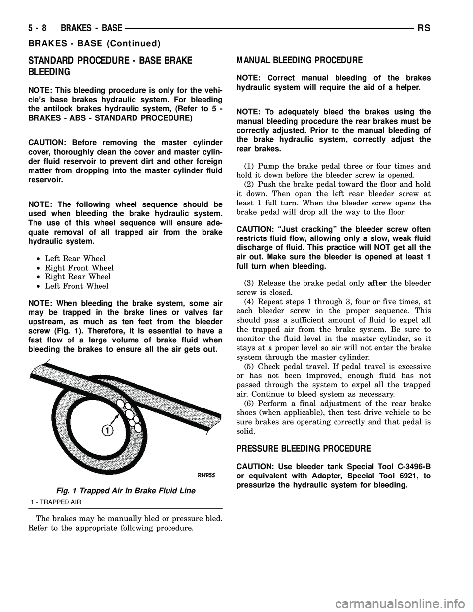
NOTE: When bleeding the brake system, some air
may be trapped in the brake lines or valves far
upstream, as much as ten feet from the bleeder
screw (Fig. 1). Therefore, it is essential to have a
fast flow of a large volume of brake fluid when
bleeding the brakes to ensure all the air gets out.
The brakes may be manually bled or pressure bled.
Refer to the appropriate following procedure.
MANUAL BLEEDING PROCEDURE
NOTE: Correct manual bleeding of the brakes
hydraulic system will require the aid of a helper.
NOTE: To adequately bleed the brakes using the
manual bleeding procedure the rear brakes must be
correctly adjusted. Prior to the manual bleeding of
the brake hydraulic system, correctly adjust the
rear brakes.
(1) Pump the brake pedal three or four times and
hold it down before the bleeder screw is opened.
(2) Push the brake pedal toward the floor and hold
it down. Then open the left rear bleeder screw at
least 1 full turn. When the bleeder screw opens the
brake pedal will drop all the way to the floor.
CAUTION: ªJust crackingº the bleeder screw often
restricts fluid flow, allowing only a slow, weak fluid
discharge of fluid. This practice will NOT get all the
air out. Make sure the bleeder is opened at least 1
full turn when bleeding.
(3) Release the brake pedal onlyafterthe bleeder
screw is closed.
(4) Repeat steps 1 through 3, four or five times, at
each bleeder screw in the proper sequence. This
should pass a sufficient amount of fluid to expel all
the trapped air from the brake system. Be sure to
monitor the fluid level in the master cylinder, so it
stays at a proper level so air will not enter the brake
system through the master cylinder.
(5) Check pedal travel. If pedal travel is excessive
or has not been improved, enough fluid has not
passed through the system to expel all the trapped
air. Continue to bleed system as necessary.
(6) Perform a final adjustment of the rear brake
shoes (when applicable), then test drive vehicle to be
sure brakes are operating correctly and that pedal is
solid.
PRESSURE BLEEDING PROCEDURE
CAUTION: Use bleeder tank Special Tool C-3496-B
or equivalent with Adapter, Special Tool 6921, to
pressurize the hydraulic system for bleeding.
Fig. 1 Trapped Air In Brake Fluid Line
1 - TRAPPED AIR
5 - 8 BRAKES - BASERS
BRAKES - BASE (Continued)
Page 120 of 2339

Follow pressure bleeder manufacturer's instruc-
tions for use of pressure bleeding equipment.
(1) Install the Adapter Master Cylinder Pressure
Bleed Cap, Special Tool 6921 on the fluid reservoir of
the master cylinder (Fig. 2). Attach the fluid hose
from the pressure bleeder to the fitting on Special
Tool 6921.
(2) Attach a clear plastic hose to the bleeder screw
at one wheel and feed the hose into a clear jar con-
taining fresh brake fluid.
(3) Open the left rear wheel bleeder screw at least
one full turnor more to obtain an adequate flow of
brake fluid.
CAUTION: ªJust crackingº the bleeder screw often
restricts fluid flow, allowing only a slow, weak fluid
discharge of fluid. This practice will NOT get all the
air out. Make sure the bleeder is opened at least 1
full turn when bleeding.
(4) After 4 to 8 ounces of brake fluid has been bled
through the hydraulic system, and an air-free flow is
maintained in the hose and jar, this will indicate a
good bleed of the hydraulic system has been
obtained.
(5) Repeat the procedure at all the other remain-
ing bleeder screws.
(6) Check pedal travel. If pedal travel is excessive
or has not been improved, enough fluid has not
passed through the system to expel all the trapped
air. Be sure to monitor the fluid level in the pressure
bleeder, so it stays at a proper level so air will not
enter the brake system through the master cylinder.
(7) Perform a final adjustment of the rear brake
shoes (when applicable), then test drive vehicle to be
sure brakes are operating correctly and that pedal is
solid.SPECIFICATIONS
BRAKE FASTENER TORQUE
DESCRIPTION N´mFt.
Lbs.In.
Lbs.
ABS ICU Mounting Bolts To
Bracket11 Ð 9 7
ABS ICU Mounting
Bracket-To-Cradle Bolts28 21 250
ABS CAB-To-HCU Mounting
Screws2Ð17
ABS Wheel Speed Sensor
Head Mounting Bolt - Front13 Ð 115
ABS Wheel Speed Sensor
Head Mounting Bolt - Rear10 Ð 90
Adjustable Pedal Position
Sensor Mounting Screws7.5 66 Ð
Adjustable Pedal Module
Mounting Screws2.0 15 Ð
Brake Tube Nuts 17 Ð 145
Brake Hose Intermediate
Bracket Bolt12 Ð 105
Brake Hose-To-Caliper
Mounting Bolt47 35 Ð
Disc Brake Caliper Guide
Pin Bolts35 26 Ð
Disc Brake Caliper Bleeder
Screw15 Ð 125
Drum Brake Wheel Cylinder
Mounting Bolts8Ð75
Drum Brake Wheel Cylinder
Mounting Bleeder screw10 Ð 80
Drum Brake Support Plate
Mounting Bolts130 95 Ð
Junction Block (Non-ABS
Brakes) Mounting Bolts28 21 250
Master Cylinder Mounting
Nuts25 19 225
Power Brake Booster
Mounting Nuts28 21 250
Proportioning Valve
Mounting Bolts54 40 Ð
Proportioning Valve Axle
Bracket Mounting Bolt20 Ð 175
Parking Brake Lever (Pedal)
Mounting Bolts And Nut28 21 250
Wheel Mounting (Lug) Nuts 135 100 Ð
Fig. 2 Tool 6921 Installed On Master Cylinder
1 - SPECIAL TOOL 6921
2 - FLUID RESERVOIR
RSBRAKES - BASE5-9
BRAKES - BASE (Continued)
Page 121 of 2339

SPECIAL TOOLS
BASE BRAKE SYSTEM
BRAKE FLUID LEVEL SWITCH
DESCRIPTION
The brake fluid level switch is located in the brake
fluid reservoir of the master cylinder (Fig. 3).
OPERATION
The purpose of the brake fluid level switch is to
provide the driver with an early warning that the
brake fluid level in the master cylinder fluid reser-
voir has dropped below a normal level. This may
indicate:
²Abnormal loss of brake fluid in the master cyl-
inder fluid reservoir resulting from a leak in the
hydraulic system.
²Brake shoe linings which have worn to a point
requiring replacement.
As the brake fluid drops below the minimum level,
the brake fluid level switch closes to complete the red
BRAKE warning indicator (lamp) circuit. This will
turn on the red BRAKE warning indicator. The mas-
ter cylinder fluid reservoir should be checked and
refilled to the Full mark with DOT 3 brake fluid.If
the brake fluid level has dropped below the add
line in the master cylinder fluid reservoir, the
entire brake hydraulic system should be
checked for evidence of a leak.
Tubes, Master Cylinder Bleed 8358
Adapter, Master Cylinder Pressure Bleed Cap 6921
Dial Indicator, C-3339
Gauge, Brake Shoe C-3919
Handle, Universal C±4171
Installer, Dust Boot C-4689 or C-4842
5 - 10 BRAKES - BASERS
BRAKES - BASE (Continued)
Page 122 of 2339
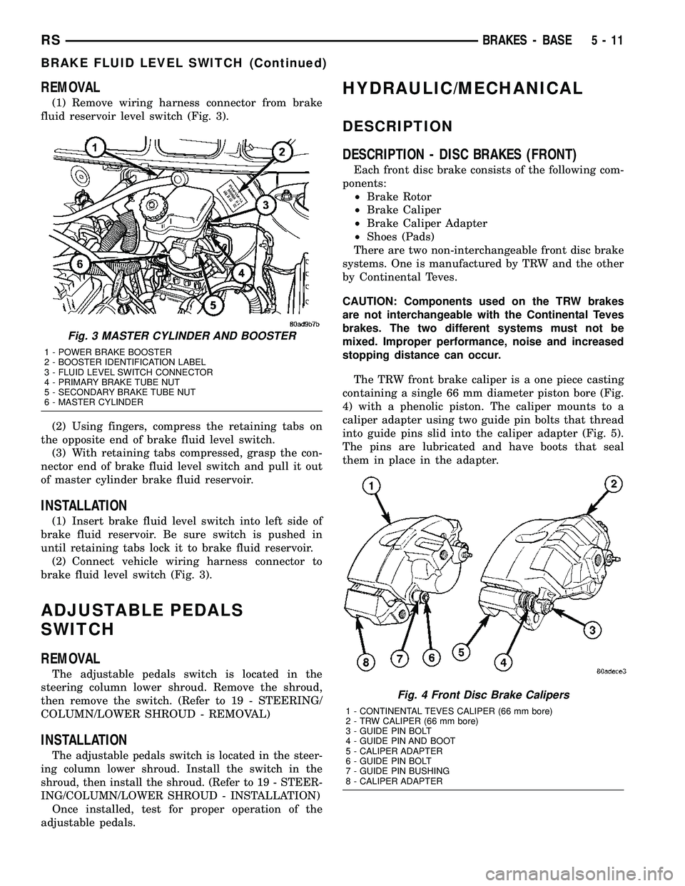
REMOVAL
(1) Remove wiring harness connector from brake
fluid reservoir level switch (Fig. 3).
(2) Using fingers, compress the retaining tabs on
the opposite end of brake fluid level switch.
(3) With retaining tabs compressed, grasp the con-
nector end of brake fluid level switch and pull it out
of master cylinder brake fluid reservoir.
INSTALLATION
(1) Insert brake fluid level switch into left side of
brake fluid reservoir. Be sure switch is pushed in
until retaining tabs lock it to brake fluid reservoir.
(2) Connect vehicle wiring harness connector to
brake fluid level switch (Fig. 3).
ADJUSTABLE PEDALS
SWITCH
REMOVAL
The adjustable pedals switch is located in the
steering column lower shroud. Remove the shroud,
then remove the switch. (Refer to 19 - STEERING/
COLUMN/LOWER SHROUD - REMOVAL)
INSTALLATION
The adjustable pedals switch is located in the steer-
ing column lower shroud. Install the switch in the
shroud, then install the shroud. (Refer to 19 - STEER-
ING/COLUMN/LOWER SHROUD - INSTALLATION)
Once installed, test for proper operation of the
adjustable pedals.
HYDRAULIC/MECHANICAL
DESCRIPTION
DESCRIPTION - DISC BRAKES (FRONT)
Each front disc brake consists of the following com-
ponents:
²Brake Rotor
²Brake Caliper
²Brake Caliper Adapter
²Shoes (Pads)
There are two non-interchangeable front disc brake
systems. One is manufactured by TRW and the other
by Continental Teves.
CAUTION: Components used on the TRW brakes
are not interchangeable with the Continental Teves
brakes. The two different systems must not be
mixed. Improper performance, noise and increased
stopping distance can occur.
The TRW front brake caliper is a one piece casting
containing a single 66 mm diameter piston bore (Fig.
4) with a phenolic piston. The caliper mounts to a
caliper adapter using two guide pin bolts that thread
into guide pins slid into the caliper adapter (Fig. 5).
The pins are lubricated and have boots that seal
them in place in the adapter.
Fig. 3 MASTER CYLINDER AND BOOSTER
1 - POWER BRAKE BOOSTER
2 - BOOSTER IDENTIFICATION LABEL
3 - FLUID LEVEL SWITCH CONNECTOR
4 - PRIMARY BRAKE TUBE NUT
5 - SECONDARY BRAKE TUBE NUT
6 - MASTER CYLINDER
Fig. 4 Front Disc Brake Calipers
1 - CONTINENTAL TEVES CALIPER (66 mm bore)
2 - TRW CALIPER (66 mm bore)
3 - GUIDE PIN BOLT
4 - GUIDE PIN AND BOOT
5 - CALIPER ADAPTER
6 - GUIDE PIN BOLT
7 - GUIDE PIN BUSHING
8 - CALIPER ADAPTER
RSBRAKES - BASE5-11
BRAKE FLUID LEVEL SWITCH (Continued)