clock CHRYSLER VOYAGER 2005 Owner's Guide
[x] Cancel search | Manufacturer: CHRYSLER, Model Year: 2005, Model line: VOYAGER, Model: CHRYSLER VOYAGER 2005Pages: 2339, PDF Size: 59.69 MB
Page 494 of 2339
UNDEPLOYED AIRBAG
WARNING: The airbags must be stored in its origi-
nal special container until used for service. At no
time should a source of electricity be permitted
near the inflator on the back of an airbag. When
carrying or handling an undeployed airbag, the trim
side of the airbag should be pointing toward the
body to minimize the possibility of personal injury
or death if accidental deployment occurs. Do not
place undeployed airbag face down on a solid sur-
face, the airbag will propel into the air if accidental
deployment occurs.
STANDARD PROCEDURE - SERVICE AFTER AN
AIRBAG DEPLOYMENT
DRIVER AIRBAG
After a Driver Airbag has been deployed due to a
collision, the followingMUSTbe replaced:
²Driver Airbag
²Clockspring Assembly
²Steering Wheel
²Complete Steering Column Assembly w/Lower
Steering Column Coupler
All other airbag and vehicle components should be
closely inspected following any airbag deployment,
and should be replaced when visible damage is
incurred.
WARNING: Do not connect the battery negative
cable (Refer to 8 - ELECTRICAL/RESTRAINTS -
DIAGNOSIS AND TESTING - AIRBAG SYSTEM). Per-
sonal injury or death may result if the system test
is not performed first.
PASSENGER AIRBAG
After a Passenger Airbag has been deployed due to
a collision. the followingMUSTbe replaced:
²Passenger Airbag
²Instrument Panel and Pad Assembly
All other airbag and vehicle components should be
closely inspected following any airbag deployment,
and should be replaced when visible damage is
incurred.
WARNING: Do not connect the battery negative
cable (Refer to 8 - ELECTRICAL/RESTRAINTS -
DIAGNOSIS AND TESTING - AIRBAG SYSTEM). Per-
sonal injury or death may result if the system test
is not performed first.
KNEE BLOCKER AIRBAG
After a Knee Blocker Airbag has been deployed due
to a collision. the followingMUSTbe replaced:
²Knee Blocker Airbag
²Instrument Panel and Pad Assembly
All other airbag and vehicle components should be
closely inspected following any airbag deployment,
and should be replaced when visible damage is
incurred.
WARNING: Do not connect the battery negative
cable (Refer to 8 - ELECTRICAL/RESTRAINTS -
DIAGNOSIS AND TESTING - AIRBAG SYSTEM). Per-
sonal injury or death may result if the system test
is not performed first.
CURTAIN AIRBAG
After a Curtain Airbag has been deployed due to a
collision. the followingMUSTbe replaced:
²Curtain Airbag Assembly
²Headliner
²A, B, and C-Pillar Trim on deployed side.
All other airbag and vehicle components should be
closely inspected following any airbag deployment,
and should be replaced when visible damage is
incurred.
WARNING: Do not connect the battery negative
cable (Refer to 8 - ELECTRICAL/RESTRAINTS -
DIAGNOSIS AND TESTING - AIRBAG SYSTEM). Per-
sonal injury or death may result if the system test
is not performed first.
OCCUPANT CLASSIFICATION SYSTEM (OCS)
After an impact event, either front, rear, or side,
the OCS system components need to be inspected
and replaced if found to be damaged.
This includes:
²Belt Tension Sensor
²Occupant Classification Module (OCM)
²Passenger Airbag ON/Off Indicator
²Seat Weight Bladder and Sensor
RSRESTRAINTS8O-7
RESTRAINTS (Continued)
Page 497 of 2339
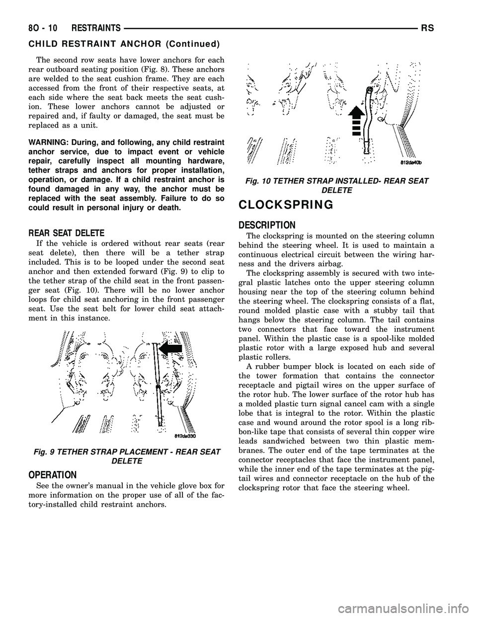
The second row seats have lower anchors for each
rear outboard seating position (Fig. 8). These anchors
are welded to the seat cushion frame. They are each
accessed from the front of their respective seats, at
each side where the seat back meets the seat cush-
ion. These lower anchors cannot be adjusted or
repaired and, if faulty or damaged, the seat must be
replaced as a unit.
WARNING: During, and following, any child restraint
anchor service, due to impact event or vehicle
repair, carefully inspect all mounting hardware,
tether straps and anchors for proper installation,
operation, or damage. If a child restraint anchor is
found damaged in any way, the anchor must be
replaced with the seat assembly. Failure to do so
could result in personal injury or death.
REAR SEAT DELETE
If the vehicle is ordered without rear seats (rear
seat delete), then there will be a tether strap
included. This is to be looped under the second seat
anchor and then extended forward (Fig. 9) to clip to
the tether strap of the child seat in the front passen-
ger seat (Fig. 10). There will be no lower anchor
loops for child seat anchoring in the front passenger
seat. Use the seat belt for lower child seat attach-
ment in this instance.
OPERATION
See the owner's manual in the vehicle glove box for
more information on the proper use of all of the fac-
tory-installed child restraint anchors.
CLOCKSPRING
DESCRIPTION
The clockspring is mounted on the steering column
behind the steering wheel. It is used to maintain a
continuous electrical circuit between the wiring har-
ness and the drivers airbag.
The clockspring assembly is secured with two inte-
gral plastic latches onto the upper steering column
housing near the top of the steering column behind
the steering wheel. The clockspring consists of a flat,
round molded plastic case with a stubby tail that
hangs below the steering column. The tail contains
two connectors that face toward the instrument
panel. Within the plastic case is a spool-like molded
plastic rotor with a large exposed hub and several
plastic rollers.
A rubber bumper block is located on each side of
the tower formation that contains the connector
receptacle and pigtail wires on the upper surface of
the rotor hub. The lower surface of the rotor hub has
a molded plastic turn signal cancel cam with a single
lobe that is integral to the rotor. Within the plastic
case and wound around the rotor spool is a long rib-
bon-like tape that consists of several thin copper wire
leads sandwiched between two thin plastic mem-
branes. The outer end of the tape terminates at the
connector receptacles that face the instrument panel,
while the inner end of the tape terminates at the pig-
tail wires and connector receptacle on the hub of the
clockspring rotor that face the steering wheel.
Fig. 9 TETHER STRAP PLACEMENT - REAR SEAT
DELETE
Fig. 10 TETHER STRAP INSTALLED- REAR SEAT
DELETE
8O - 10 RESTRAINTSRS
CHILD RESTRAINT ANCHOR (Continued)
Page 498 of 2339
Service replacement clocksprings are shipped pre-
centered and with a molded plastic shield that snaps
onto the rotor over the release button. The release
button secures the centered clockspring rotor to the
clockspring case and the shield prevents the release
button from being inadvertently depressed during
shipment and handling, but the shield must be
removed from the clockspring after it is installed on
the steering column (Refer to 8 - ELECTRICAL/RE-
STRAINTS/CLOCKSPRING - STANDARD PROCE-
DURE).
The clockspring cannot be repaired. If the clock-
spring is faulty, damaged, or if the driver airbag has
been deployed, the clockspring must be replaced.
OPERATION
The clockspring is a mechanical electrical circuit
component that is used to provide continuous electri-
cal continuity between the fixed instrument panel
wire harness and the electrical components mounted
on or in the rotating steering wheel. The rotating
electrical components include the driver airbag, the
horn switch, the speed control switches, and the
remote radio switches, if the vehicle is so equipped.
The clockspring case is positioned and secured to the
upper steering column housing near the top of the
steering column. The connector receptacles on the
tail of the clockspring case connect the clockspring to
the vehicle electrical system through two connectors
from the instrument panel wire harness.
The clockspring rotor is movable and is keyed by
the tower formation that is molded onto the upper
surface of the rotor hub to an opening that is cast
into the steering wheel armature. Rubber bumper
blocks on either side of the clockspring tower forma-
tion eliminate contact noise between the clockspring
tower and the steering wheel. The lobe of the turn
signal cancel cam on the lower surface of the clock-
spring rotor hub contacts a turn signal cancel actua-
tor of the multi-function switch to provide automatic
turn signal cancellation. The yellow or black-sleeved
pigtail wires on the upper surface of the clockspring
rotor connect the clockspring to the driver airbag,
while a steering wheel wire harness connects the
connector receptacle on the upper surface of the
clockspring rotor to the horn switch and, if the vehi-
cle is so equipped, to the optional speed control
switches and remote radio switches on the steering
wheel.
The clockspring tape has travel limits and can be
damaged by being wound too tightly during full stop-
to-stop steering wheel rotation. To prevent this from
occurring, the clockspring is centered when it is
installed on the steering column. Centering the clock-
spring indexes the clockspring tape to the movable
steering components so that the tape can operatewithin its designed travel limits. However, if the
clockspring is removed from the steering column or if
the steering shaft is disconnected from the steering
gear, the clockspring spool can change position rela-
tive to the movable steering components and must be
re-centered following completion of the service or the
tape may be damaged (Refer to 8 - ELECTRICAL/
RESTRAINTS/CLOCKSPRING - STANDARD PRO-
CEDURE).
Service replacement clocksprings are shipped pre-
centered and with a plastic shield installed over the
clockspring release button. This shield should not be
removed and the release button should not be
depressed until the clockspring has been installed on
the steering column. If the release button is
depressed before the clockspring is installed on a
steering column, the clockspring centering procedure
must be performed (Refer to 8 - ELECTRICAL/RE-
STRAINTS/CLOCKSPRING - STANDARD PROCE-
DURE).
STANDARD PROCEDURE - CLOCKSPRING
CENTERING
If the rotating tape (wire coil) in the clockspring is
not positioned properly with the steering wheel and
the front wheels, the clockspring may fail. The fol-
lowing procedure MUST BE USED to center the
clockspring if it is not known to be properly posi-
tioned, or if the front wheels were moved from the
straight ahead position.
(1) Position steering wheel and front wheels
straight ahead.
(2) Release hood latch and open hood.
(3) Disconnect and isolate the battery negative
cable.
(4) Wait two minutes for the system reserve capac-
itor to discharge before beginning any airbag compo-
nent service.
(5) Remove driver airbag from steering wheel
(Refer to 8 - ELECTRICAL/RESTRAINTS/DRIVER
AIRBAG - REMOVAL).
(6) Disconnect wire connectors from back of driver
airbag.
(7) Disconnect the 2±way connector from remote
radio control harness (if equipped).
(8) Disconnect the 4±way harness connector from
the speed control (if equipped)/horn harness to the
clockspring.
(9) Remove steering wheel (Refer to 19 - STEER-
ING/COLUMN/STEERING WHEEL - REMOVAL).
(10) Rotate the clockspring rotor clockwise until
the rotor stops. Do not apply excessive force.
(11) From the end of travel, rotate the rotor two
turns counterclockwise until the wires end up at the
top.
RSRESTRAINTS8O-11
CLOCKSPRING (Continued)
Page 499 of 2339
(12) Install the steering wheel (Refer to 19 -
STEERING/COLUMN/STEERING WHEEL -
INSTALLATION).
(13) Connect the 4±way harness connector to the
speed control/horn harness to the clockspring.
(14) Connect the 2±way connector to the remote
radio control harness.
(15) Install the driver airbag (Refer to 8 - ELEC-
TRICAL/RESTRAINTS/DRIVER AIRBAG - INSTAL-
LATION). Torque the two screws to 10 N´m (90 in.
lbs.).
WARNING: Do not connect the battery negative
cable (Refer to 8 - ELECTRICAL/RESTRAINTS -
DIAGNOSIS AND TESTING). Personal injury or
death may result if the system test is not performed
properly.
REMOVAL
(1) Position steering wheel and front wheels
straight ahead.
(2) Release hood latch and open hood.
(3) Disconnect and isolate the battery negative
cable.
(4)
WARNING: Wait two minutes for the airbag system
reserve capacitor to discharge before beginning
any airbag system or component service. Failure to
do so may result in accidental airbag deployment,
personal injury or death.
(5) Remove driver airbag from steering wheel
(Refer to 8 - ELECTRICAL/RESTRAINTS/DRIVER
AIRBAG - REMOVAL).
(6) Disconnect wire connectors from back of driver
airbag.
(7) Disconnect the 2±way connector from remote
radio control harness.
(8) Disconnect the 4±way harness connector from
the speed control/horn harness to the clockspring.
(9) Remove steering wheel (Refer to 19 - STEER-
ING/COLUMN/STEERING WHEEL - REMOVAL).
(10) Remove steering column shrouds and discon-
nect traction control wire connector (if equipped)
(Refer to 19 - STEERING/COLUMN/LOWER
SHROUD - REMOVAL).
(11) Disconnect 4-way and 6-way connectors
between the clockspring and the instrument panel
wiring harness.
(12) Remove clockspring from column assembly by
removing the two retaining screws that attach the
clock spring to the column.
INSTALLATION
(1) Install the clockspring on the column.
(2) Connect the 4-way and 6-way connectors
between the clockspring and the instrument panel
wiring harness.
(3) Install the steering column shrouds and con-
nect traction control wire connector (if equipped)
(Refer to 19 - STEERING/COLUMN/LOWER
SHROUD - INSTALLATION).
(4) Install the steering wheel (Refer to 19 -
STEERING/COLUMN/STEERING WHEEL -
INSTALLATION).
(5) Connect the 4±way harness connector to the
speed control/horn harness to the clockspring.
(6) Connect the 2±way connector to the remote
radio control harness (if equipped).
(7) Install the driver airbag (Refer to 8 - ELEC-
TRICAL/RESTRAINTS/DRIVER AIRBAG - INSTAL-
LATION). Torque the two screws to 10 N´m (90 in.
lbs.).
WARNING: Do not connect the battery negative
cable (Refer to 8 - ELECTRICAL/RESTRAINTS -
DIAGNOSIS AND TESTING - AIRBAG SYSTEM). Per-
sonal injury or death may result if the system test
is not performed first.
CURTAIN AIRBAG
DESCRIPTION
Curtain Airbags (Fig. 11) are available when it is
also equipped with dual front airbags. These airbags
are passive and inflatable, Supplemental Restraint
System (SRS) components, and vehicles with this
equipment can be readily identified by a molded
identification trim button with the ªSRS - AIRBAGº
logo (Fig. 12) located on the B-pillar and C-pillar
upper trim panels. This system is designed to reduce
injuries to the vehicle occupants in the event of a
side impact collision.
Curtain airbags have two individually controlled
curtain airbag units. These airbag units are con-
cealed and mounted above the headliner where they
are each secured to one of the roof side rails (Fig.
13). Each airbag cushion is contained within a fabric
wrap that extends along the roof rail from the A-pil-
lar at the front of the vehicle to just behind the
D-pillar at the rear of the vehicle. One tether extends
down the A-pillar from the front of the airbag cush-
ion, and a second tether extends to the roof rail at
the D-pillar. The end of the A-pillar tether is secured
to a slot in the sheet metal with a metal hook
retained by a bolt. The D-pillar tether is attached to
the d-pillar.
8O - 12 RESTRAINTSRS
CLOCKSPRING (Continued)
Page 503 of 2339
INSTALLATION
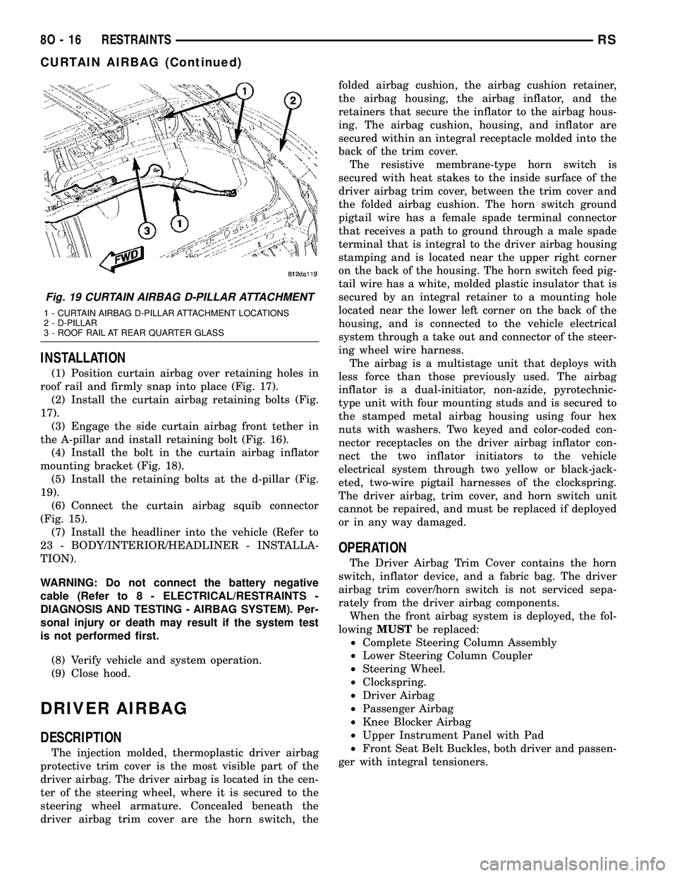
(1) Position curtain airbag over retaining holes in
roof rail and firmly snap into place (Fig. 17).
(2) Install the curtain airbag retaining bolts (Fig.
17).
(3) Engage the side curtain airbag front tether in
the A-pillar and install retaining bolt (Fig. 16).
(4) Install the bolt in the curtain airbag inflator
mounting bracket (Fig. 18).
(5) Install the retaining bolts at the d-pillar (Fig.
19).
(6) Connect the curtain airbag squib connector
(Fig. 15).
(7) Install the headliner into the vehicle (Refer to
23 - BODY/INTERIOR/HEADLINER - INSTALLA-
TION).
WARNING: Do not connect the battery negative
cable (Refer to 8 - ELECTRICAL/RESTRAINTS -
DIAGNOSIS AND TESTING - AIRBAG SYSTEM). Per-
sonal injury or death may result if the system test
is not performed first.
(8) Verify vehicle and system operation.
(9) Close hood.
DRIVER AIRBAG
DESCRIPTION
The injection molded, thermoplastic driver airbag
protective trim cover is the most visible part of the
driver airbag. The driver airbag is located in the cen-
ter of the steering wheel, where it is secured to the
steering wheel armature. Concealed beneath the
driver airbag trim cover are the horn switch, thefolded airbag cushion, the airbag cushion retainer,
the airbag housing, the airbag inflator, and the
retainers that secure the inflator to the airbag hous-
ing. The airbag cushion, housing, and inflator are
secured within an integral receptacle molded into the
back of the trim cover.
The resistive membrane-type horn switch is
secured with heat stakes to the inside surface of the
driver airbag trim cover, between the trim cover and
the folded airbag cushion. The horn switch ground
pigtail wire has a female spade terminal connector
that receives a path to ground through a male spade
terminal that is integral to the driver airbag housing
stamping and is located near the upper right corner
on the back of the housing. The horn switch feed pig-
tail wire has a white, molded plastic insulator that is
secured by an integral retainer to a mounting hole
located near the lower left corner on the back of the
housing, and is connected to the vehicle electrical
system through a take out and connector of the steer-
ing wheel wire harness.
The airbag is a multistage unit that deploys with
less force than those previously used. The airbag
inflator is a dual-initiator, non-azide, pyrotechnic-
type unit with four mounting studs and is secured to
the stamped metal airbag housing using four hex
nuts with washers. Two keyed and color-coded con-
nector receptacles on the driver airbag inflator con-
nect the two inflator initiators to the vehicle
electrical system through two yellow or black-jack-
eted, two-wire pigtail harnesses of the clockspring.
The driver airbag, trim cover, and horn switch unit
cannot be repaired, and must be replaced if deployed
or in any way damaged.
OPERATION
The Driver Airbag Trim Cover contains the horn
switch, inflator device, and a fabric bag. The driver
airbag trim cover/horn switch is not serviced sepa-
rately from the driver airbag components.
When the front airbag system is deployed, the fol-
lowingMUSTbe replaced:
²Complete Steering Column Assembly
²Lower Steering Column Coupler
²Steering Wheel.
²Clockspring.
²Driver Airbag
²Passenger Airbag
²Knee Blocker Airbag
²Upper Instrument Panel with Pad
²Front Seat Belt Buckles, both driver and passen-
ger with integral tensioners.
Fig. 19 CURTAIN AIRBAG D-PILLAR ATTACHMENT
1 - CURTAIN AIRBAG D-PILLAR ATTACHMENT LOCATIONS
2 - D-PILLAR
3 - ROOF RAIL AT REAR QUARTER GLASS
8O - 16 RESTRAINTSRS
CURTAIN AIRBAG (Continued)
Page 504 of 2339
CARE OF UNDEPLOYED AIRBAGS
WARNING: Airbags must be stored in their original
special container until used for service. At no time
should a source of electricity be permitted near the
inflator on the back of an airbag. When carrying or
handling an undeployed airbag, the trim side of the
airbag should be pointing toward the body to mini-
mize possibility of injury if accidental deployment
occurs. Do not place undeployed airbag face down
on a solid surface, the airbag will propel into the air
if accidental deployment occurs.
REMOVAL
DEPLOYED AIRBAG
(1) Clean powder residue from interior of vehicle
(Fig. 4).
(2) Position steering wheel and front wheels
straight ahead.
(3) Release hood latch and open hood.
(4) Disconnect and isolate the battery negative
cable.
(5)
WARNING: Wait two minutes for the airbag system
reserve capacitor to discharge before beginning
any airbag system or component service. Failure to
do so may result in accidental airbag deployment,
personal injury or death.
(6) Remove two screws retaining driver airbag to
steering wheel.
(7) Disconnect wire connectors from back of driver
airbag.
(8) Disconnect the 2±way connector from remote
radio control harness.
(9) Disconnect the 4±way harness connector from
the speed control/horn harness to the clockspring.
(10) Remove steering wheel (Refer to 19 - STEER-
ING/COLUMN/STEERING WHEEL - REMOVAL).
(11) Remove steering column shrouds and discon-
nect traction control wire connector (if equipped)
(Refer to 19 - STEERING/COLUMN/LOWER
SHROUD - REMOVAL).
(12) Disconnect 4-way and 6-way connectors
between the clockspring and the instrument panel
wiring harness.
(13) Remove clockspring from column assembly by
removing the two retaining screws that attach the
clockspring to the column.
WARNING: The clockspring, steering wheel, and
complete steering column assembly w/lower steer-
ing column coupler must be replaced also in theevent of a driver airbag deployment. Personal injury
or death may result if not replaced.
UNDEPLOYED AIRBAG
(1) Release hood latch and open hood.
(2) Disconnect and isolate the battery negative
cable.
WARNING: Wait two minutes for the system reserve
capacitor to discharge before beginning any airbag
component service. Personal injury or death may
result.
(3) Remove two screws retaining driver airbag to
steering wheel.
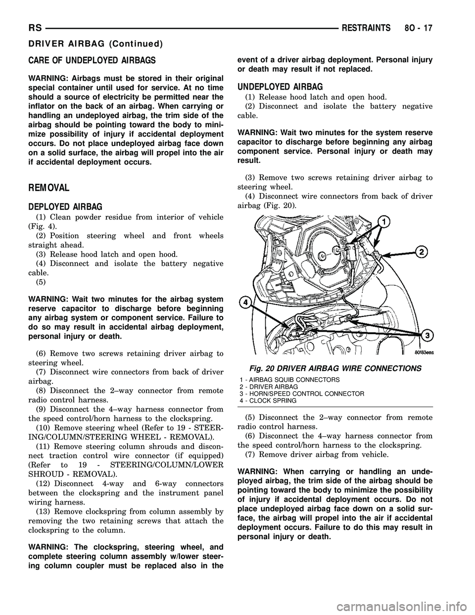
(4) Disconnect wire connectors from back of driver
airbag (Fig. 20).
(5) Disconnect the 2±way connector from remote
radio control harness.
(6) Disconnect the 4±way harness connector from
the speed control/horn harness to the clockspring.
(7) Remove driver airbag from vehicle.
WARNING: When carrying or handling an unde-
ployed airbag, the trim side of the airbag should be
pointing toward the body to minimize the possibility
of injury if accidental deployment occurs. Do not
place undeployed airbag face down on a solid sur-
face, the airbag will propel into the air if accidental
deployment occurs. Failure to do this may result in
personal injury or death.
Fig. 20 DRIVER AIRBAG WIRE CONNECTIONS
1 - AIRBAG SQUIB CONNECTORS
2 - DRIVER AIRBAG
3 - HORN/SPEED CONTROL CONNECTOR
4 - CLOCK SPRING
RSRESTRAINTS8O-17
DRIVER AIRBAG (Continued)
Page 505 of 2339
INSTALLATION
DEPLOYED AIRBAG
(1) Perform clean up procedure (Refer to 8 - ELEC-
TRICAL/RESTRAINTS - STANDARD PROCEDURE
- SERVICE AFTER AN AIRBAG DEPLOYMENT).
(2) Install a new steering column assembly and
lower steering column coupler (Refer to 19 - STEER-
ING/COLUMN - INSTALLATION).
(3) Install the new clockspring.
(4) Connect the 4-way and 6-way connectors
between the clockspring and the instrument panel
wiring harness.
(5) Install the steering column shrouds and con-
nect traction control wire connector (if equipped)
(Refer to 19 - STEERING/COLUMN/LOWER
SHROUD - INSTALLATION).
(6) Install the steering wheel (Refer to 19 -
STEERING/COLUMN/STEERING WHEEL -
INSTALLATION).
(7) Connect the 4±way harness connector to the
speed control/horn harness to the clockspring.
(8) Connect the 2±way connector to the remote
radio control harness.
(9) Install the driver airbag and the two screws
retaining the airbag. Tighten screws to 10 N´m (90
in. lbs.)
WARNING: Do not connect the battery negative
cable (Refer to 8 - ELECTRICAL/RESTRAINTS -
DIAGNOSIS AND TESTING - AIRBAG SYSTEM). Per-
sonal injury or death may result if the system test
is not performed first.
UNDEPLOYED AIRBAG
(1) Connect the harness connector on the driver
airbag trim cover (horn, speed controls) to the clock-
spring.
(2) Connect the squib connectors to the driver air-
bag.
(3) Position the driver airbag into the steering
wheel.
(4) Install the two screws retaining the airbag.
Tighten screws to 10 N´m (90 in. lbs.)
WARNING: Do not connect the battery negative
cable (Refer to 8 - ELECTRICAL/RESTRAINTS -
DIAGNOSIS AND TESTING - AIRBAG SYSTEM). Per-
sonal injury or death may result if the system test
is not performed first.
IMPACT SENSOR
DESCRIPTION
FRONT IMPACT SENSORS
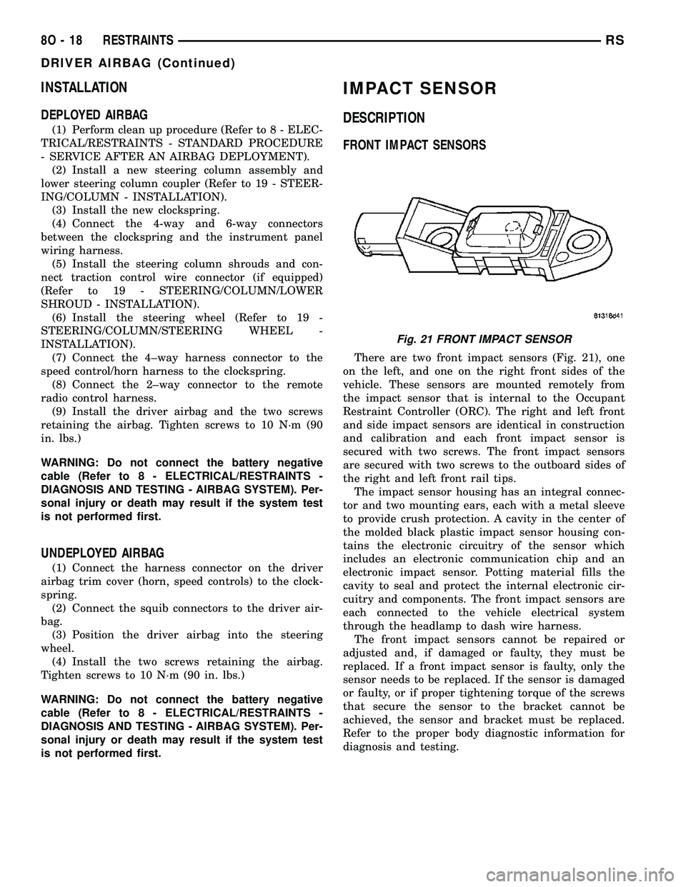
There are two front impact sensors (Fig. 21), one
on the left, and one on the right front sides of the
vehicle. These sensors are mounted remotely from
the impact sensor that is internal to the Occupant
Restraint Controller (ORC). The right and left front
and side impact sensors are identical in construction
and calibration and each front impact sensor is
secured with two screws. The front impact sensors
are secured with two screws to the outboard sides of
the right and left front rail tips.
The impact sensor housing has an integral connec-
tor and two mounting ears, each with a metal sleeve
to provide crush protection. A cavity in the center of
the molded black plastic impact sensor housing con-
tains the electronic circuitry of the sensor which
includes an electronic communication chip and an
electronic impact sensor. Potting material fills the
cavity to seal and protect the internal electronic cir-
cuitry and components. The front impact sensors are
each connected to the vehicle electrical system
through the headlamp to dash wire harness.
The front impact sensors cannot be repaired or
adjusted and, if damaged or faulty, they must be
replaced. If a front impact sensor is faulty, only the
sensor needs to be replaced. If the sensor is damaged
or faulty, or if proper tightening torque of the screws
that secure the sensor to the bracket cannot be
achieved, the sensor and bracket must be replaced.
Refer to the proper body diagnostic information for
diagnosis and testing.
Fig. 21 FRONT IMPACT SENSOR
8O - 18 RESTRAINTSRS
DRIVER AIRBAG (Continued)
Page 517 of 2339
WARNING: Never replace both the Occupant
Restraint Controller (ORC) and the Occupant Clas-
sification Module (OCM) at the same time. If both
require replacement, replace one, then perform the
Airbag System test (Refer to 8 - ELECTRICAL/RE-
STRAINTS - DIAGNOSIS AND TESTING - AIRBAG
SYSTEM) before replacing the other. Both the ORC
and the OCM store Occupant Classification System
(OCS) calibration data, which they transfer to one
another when one of them is replaced. If both are
replaced at the same time, an irreversible fault will
be set in both modules and the OCS may malfunc-
tion and result in personal injury or death.
(1) Install the ORC into vehicle (Fig. 39).
(2) Connect the wire connector to the ORC (Fig.
39).
(3) Install three bolts holding ORC to floor bracket
(Fig. 39). Torque bolts to 7.3 - 9.6 N´m (65 to 85 in.
lbs.)
(4) Install the storage bin onto the instrument
panel (Refer to 23 - BODY/INSTRUMENT PANEL/
STORAGE BIN - INSTALLATION).
WARNING: Do not connect the battery negative
cable (Refer to 8 - ELECTRICAL/RESTRAINTS -
DIAGNOSIS AND TESTING - AIRBAG SYSTEM). Per-
sonal injury or death may result if the system test
is not performed first.
(5) Verify vehicle and system operation.
(6) Close hood.
PASSENGER AIRBAG
DESCRIPTION
WARNING: Never disassemble the passenger air-
bag. The passenger airbag has no serviceable
parts. If tampered with internally, the airbag could
deploy and result in personal injury or death.
The Passenger Airbag is located beneath the
instrument panel and pad assembly. The airbag is
mounted to the back side of the instrument panel
reinforcement.
The instrument panel top pad is the most visible
part of the passenger airbag system. Located under
the instrument panel top pad are the airbag door, the
passenger airbag cushion and the airbag cushion
supporting components.
The passenger airbag includes a magnesium hous-
ing within which the cushion and inflator are
mounted and sealed.
Following a passenger airbag deployment, the pas-
senger airbag and the instrument panel must bereplaced. The passenger airbag cannot be repaired,
and must be replaced if deployed or damaged in any
way.
OPERATION
The passenger airbag is equipped with two infla-
tors, each with three levels of pressure output. The
inflators seal the hole in the airbag cushion so it can
discharge the gas it produces directly into the cush-
ion when supplied with the proper electrical signal.
Following an airbag deployment, the airbag cushion
quickly deflates by venting this gas through the
cushion material towards the instrument panel.
The passenger airbag is secured with screws to the
instrument panel beneath the instrument panel top
pad and above the glove box opening. The instrument
panel top pad above the glove box opening conceals
the airbag door and a predetermined hinge line
beneath its decorative cover. Upon airbag deploy-
ment, the top pad will bend at the hinge line and the
door will fold back out of the way onto the top of the
instrument panel.
When the front airbag system is deployed, the fol-
lowingMUSTbe replaced:
²Complete Steering Column Assembly.
²Lower Steering Column Coupler.
²Steering Wheel.
²Clock Spring.
²Driver Airbag.
²Passenger Airbag.
²Upper Instrument Panel with Pad.
CARE OF UNDEPLOYED AIRBAGS
Airbags must be stored in their original special
container until used for service. At no time should a
source of electricity be permitted near the inflator on
the back of an airbag. When carrying or handling an
undeployed airbag, the trim side of the airbag should
be pointing away from the body to minimize possibil-
ity of injury if accidental deployment occurs. Do not
place undeployed airbag face down on a solid surface,
the airbag will propel into the air if accidental
deployment occurs.
REMOVAL
DEPLOYED AIRBAG
(1) Open hood.
(2) Disconnect and isolate the battery negative
cable.
(3)
8O - 30 RESTRAINTSRS
OCCUPANT RESTRAINT CONTROLLER (Continued)
Page 536 of 2339
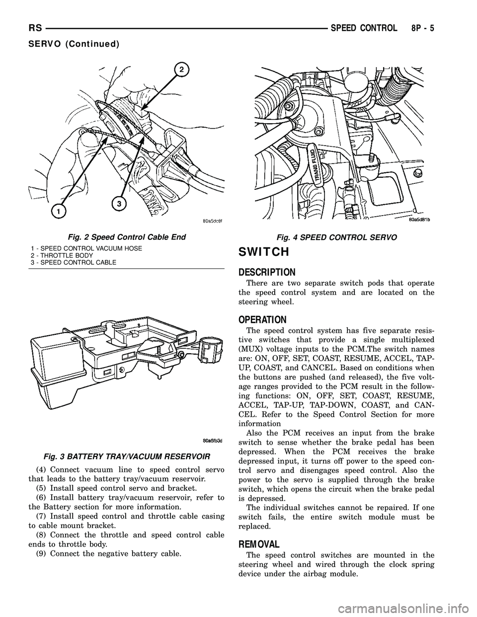
(4) Connect vacuum line to speed control servo
that leads to the battery tray/vacuum reservoir.
(5) Install speed control servo and bracket.
(6) Install battery tray/vacuum reservoir, refer to
the Battery section for more information.
(7) Install speed control and throttle cable casing
to cable mount bracket.
(8) Connect the throttle and speed control cable
ends to throttle body.
(9) Connect the negative battery cable.
SWITCH
DESCRIPTION
There are two separate switch pods that operate
the speed control system and are located on the
steering wheel.
OPERATION
The speed control system has five separate resis-
tive switches that provide a single multiplexed
(MUX) voltage inputs to the PCM.The switch names
are: ON, OFF, SET, COAST, RESUME, ACCEL, TAP-
UP, COAST, and CANCEL. Based on conditions when
the buttons are pushed (and released), the five volt-
age ranges provided to the PCM result in the follow-
ing functions: ON, OFF, SET, COAST, RESUME,
ACCEL, TAP-UP, TAP-DOWN, COAST, and CAN-
CEL. Refer to the Speed Control Section for more
information
Also the PCM receives an input from the brake
switch to sense whether the brake pedal has been
depressed. When the PCM receives the brake
depressed input, it turns off power to the speed con-
trol servo and disengages speed control. Also the
power to the servo is supplied through the brake
switch, which opens the circuit when the brake pedal
is depressed.
The individual switches cannot be repaired. If one
switch fails, the entire switch module must be
replaced.
REMOVAL
The speed control switches are mounted in the
steering wheel and wired through the clock spring
device under the airbag module.
Fig. 2 Speed Control Cable End
1 - SPEED CONTROL VACUUM HOSE
2 - THROTTLE BODY
3 - SPEED CONTROL CABLE
Fig. 3 BATTERY TRAY/VACUUM RESERVOIR
Fig. 4 SPEED CONTROL SERVO
RSSPEED CONTROL8P-5
SERVO (Continued)
Page 537 of 2339
WARNING: IF REMOVAL OF AIRBAG MODULE IS
NECESSARY, REFER TO THE RESTRAINT SYS-
TEMS SECTION FOR MORE INFORMATION.
(1) Remove the negative battery cable.
(2) Turn off ignition.
(3) Remove the air bag, refer to the restraint sec-
tion for more information.
(4) Remove the screw from bottom of the switch.
(5) Remove switch from steering wheel.
(6) Disconnect two-way electrical connector.
(7) Repeat for the other switch.
INSTALLATION
The speed control switches are mounted in the
steering wheel and wired through the clock spring
device under the airbag module.
WARNING: IF REMOVAL OF AIRBAG MODULE IS
NECESSARY, REFER TO THE RESTRAINT SYS-
TEMS SECTION FOR MORE INFORMATION.
(1) Connect two-way electrical connector.
(2) Install switch.
(3) Install screw for the switch.
(4) Repeat for the other switch.
(5) Install the air bag, refer to the restraint section
for more information.
(6) Install the negative battery cable.
VACUUM RESERVOIR
DESCRIPTION
The vacuum reservoir is located in the engine com-
partment. It is made of plastic.
OPERATION
The reservoir stores engine vacuum. Manifold vac-
uum is supplied from the brake booster check valve.
The speed control vacuum supply hose has a check
valve at the source (brake booster) to maintain the
highest available vacuum level in the servo, reservoir
and vacuum hoses. When engine vacuum drops, as in
climbing a grade while driving, the reservoir supplies
the vacuum needed to maintain proper speed control
operation. The vacuum reservoir cannot be repaired
and must be replaced if faulty.
REMOVAL
(1) Release hood latch and open hood.
(2) Disconnect the negative battery cable.
(3) Disconnect the vacuum line to the battery tray/
vacuum reservoir.
(4) Remove battery tray/vacuum reservoir, refer to
the Battery section for more information.
INSTALLATION
(1) Install battery tray/vacuum reservoir, refer to
the Battery section for more information.
(2) Connect vacuum line that leads to the battery
tray/vacuum reservoir.
(3) Connect the negative battery cable.
8P - 6 SPEED CONTROLRS
SWITCH (Continued)