ESP CHRYSLER VOYAGER 2020 Workshop Manual
[x] Cancel search | Manufacturer: CHRYSLER, Model Year: 2020, Model line: VOYAGER, Model: CHRYSLER VOYAGER 2020Pages: 516, PDF Size: 28.69 MB
Page 287 of 516
STARTING AND OPERATING285
The following table shows the approximate
distances for each zone:
Modes Of Operation
“Manual” activation of the Surround View
camera is selected by pressing the Surround
View Camera soft key located in the “Controls”
screen within the Uconnect system. Top View
The Top view will show in the Uconnect System
with Rear View and Front View in a split view
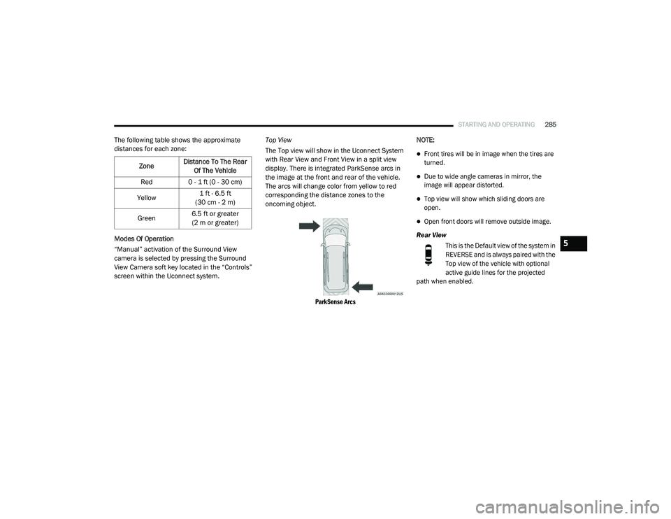
display. There is integrated ParkSense arcs in
the image at the front and rear of the vehicle.
The arcs will change color from yellow to red
corresponding the distance zones to the
oncoming object.
ParkSense Arcs
NOTE:
Front tires will be in image when the tires are
turned.
Due to wide angle cameras in mirror, the
image will appear distorted.
Top view will show which sliding doors are
open.
Open front doors will remove outside image.
Rear View This is the Default view of the system in
REVERSE and is always paired with the
Top view of the vehicle with optional
active guide lines for the projected
path when enabled.
Zone
Distance To The Rear
Of The Vehicle
Red 0 - 1 ft (0 - 30 cm)
Yellow 1 ft - 6.5 ft
(30 cm - 2 m)
Green 6.5 ft or greater
(2 m or greater)
5
20_RU_OM_EN_US_t.book Page 285
Page 288 of 516

286STARTING AND OPERATING
(Continued)
Rear Cross Path ViewPressing the Rear Cross Path soft key
will give the driver a wider angle view of
the rear camera system. The Top view
will be disabled when this is selected
Front View The Front view will show you what is
immediately in front of the vehicle and
is always paired with the Top view of
the vehicle.
Front Cross Path View
Pressing the Front Cross Path soft key will
give the driver a wider angle view of the
front camera system. The Top view will be
disabled when this is selected.
Deactivation
The system can be deactivated in the following
conditions:
The speed of the vehicle reaches greater
than 8 mph (13 km/h).
The vehicle shifted into PARK from a different
gear.
If the vehicle is in any gear other than
REVERSE, press the “X” button.
The camera delay system is turned off manu -
ally through the Uconnect settings menu.
Refer to “Uconnect Settings” in “Multimedia”
for further information.
NOTE:
If snow, ice, mud, or any foreign substance
builds up on the camera lenses, clean the
lenses, rinse with water, and dry with a soft
cloth. Do not cover the lenses.
If a malfunction with the system has
occurred, see an authorized dealer.REFUELING THE VEHICLE
There is no fuel filler cap. Two flapper doors
inside the pipe seal the system.
WARNING!
Drivers must be careful when backing up even
when using the Surround View Camera. Always
check carefully behind your vehicle, and be
sure to check for pedestrians, animals, other
vehicles, obstructions, or blind spots before
backing up. You are responsible for the safety
of your surroundings and must continue to pay
attention while backing up. Failure to do so can
result in serious injury or death.
CAUTION!
To avoid vehicle damage, Surround View
should only be used as a parking aid. The
Surround View camera is unable to view
every obstacle or object in your drive path.
To avoid vehicle damage, the vehicle must
be driven slowly when using Surround View
to be able to stop in time when an obstacle
is seen. It is recommended that the driver
look frequently over his/her shoulder when
using Surround View.
WARNING!
Never have any smoking materials lit in or
near the vehicle when the fuel door is open
or the tank is being filled.
Never add fuel when the engine is running.
This is in violation of most state and federal
fire regulations and may cause the
“Malfunction Indicator Light” to turn on.
20_RU_OM_EN_US_t.book Page 286
Page 303 of 516
301
IN CASE OF EMERGENCY
HAZARD WARNING FLASHERS
The Hazard Warning Flashers switch is located
in the lower center area of the instrument
panel.
Push the switch to turn on the Hazard
Warning Flashers. When the switch is
activated, all directional turn signals
will flash on and off to warn oncoming
traffic of an emergency. Push the switch a second
time to turn off the Hazard Warning Flashers.
This is an emergency warning system and it
should not be used when the vehicle is in
motion. Use it when your vehicle is disabled and
it is creating a safety hazard for other motorists.
When you must leave the vehicle to seek
assistance, the Hazard Warning Flashers will
continue to operate even though the ignition is
placed in the OFF position.
NOTE:
With extended use, the Hazard Warning
Flashers may wear down your battery.
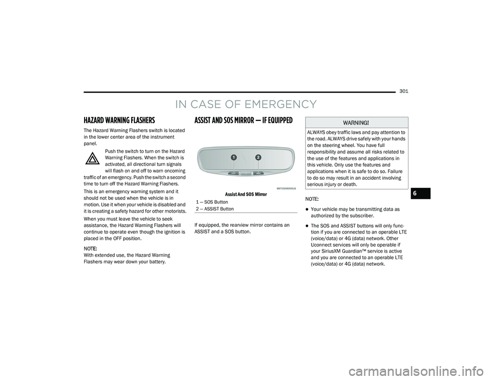
ASSIST AND SOS MIRROR — IF EQUIPPED
Assist And SOS Mirror
If equipped, the rearview mirror contains an
ASSIST and a SOS button. NOTE:
Your vehicle may be transmitting data as
authorized by the subscriber.
The SOS and ASSIST buttons will only func
-
tion if you are connected to an operable LTE
(voice/data) or 4G (data) network. Other
Uconnect services will only be operable if
your SiriusXM Guardian™ service is active
and you are connected to an operable LTE
(voice/data) or 4G (data) network.
1 — SOS Button
2 — ASSIST Button
WARNING!
ALWAYS obey traffic laws and pay attention to
the road. ALWAYS drive safely with your hands
on the steering wheel. You have full
responsibility and assume all risks related to
the use of the features and applications in
this vehicle. Only use the features and
applications when it is safe to do so. Failure
to do so may result in an accident involving
serious injury or death.
6
20_RU_OM_EN_US_t.book Page 301
Page 304 of 516
302IN CASE OF EMERGENCY
ASSIST Call
The ASSIST Button is used to automatically
connect you to any one of the following support
centers:
Roadside Assistance – If you get a flat tire, or
need a tow, just push the ASSIST button and
you will be connected to a representative for
assistance. Roadside Assistance will know
what vehicle is being driven and its location.
Additional fees may apply for roadside assis -
tance.
SiriusXM Guardian™ Customer Care –
In-vehicle support for SiriusXM Guardian™.
Vehicle Customer Care – Total support for all
other vehicle issues.
SOS Call
1. Push the SOS Call button on the Rearview Mirror.
NOTE:
In case the SOS Call button is pushed in error,
there will be a 10 second delay before the SOS
Call system initiates a call to a SOS operator. To
cancel the SOS Call connection, push the SOS call button on the Rearview Mirror or press the
cancellation button on the Device Screen.
Termination of the SOS Call will turn off the
green LED light on the Rearview Mirror.
2. The LED light located between the ASSIST
and SOS buttons on the Rearview Mirror will
turn green once a connection to a SOS
operator has been made.
3. Once a connection between the vehicle and a SOS operator is made, the SOS Call
system may transmit the following
important vehicle information to a SOS
operator: Indication that the occupant placed a
SOS Call
The vehicle brand
The last known GPS coordinates of the
vehicle
4. You should be able to speak with the SOS operator through the vehicle audio system
to determine if additional assistance is
needed. NOTE:
Your vehicle may be transmitting data as
authorized by the subscriber.
Once a connection is made between the
vehicle’s SOS Call system and the SOS oper
-
ator, the SOS operator may be able to open a
voice connection with the vehicle to deter -
mine if additional assistance is needed. Once
the SOS operator opens a voice connection
with the vehicle’s SOS Call system, the oper -
ator should be able to speak with you or other
vehicle occupants and hear sounds occurring
WARNING!
ALWAYS obey traffic laws and pay attention to
the road. ALWAYS drive safely with your hands
on the steering wheel. You have full
responsibility and assume all risks related to
the use of the features and applications in
this vehicle. Only use the features and
applications when it is safe to do so. Failure
to do so may result in an accident involving
serious injury or death.
20_RU_OM_EN_US_t.book Page 302
Page 305 of 516
IN CASE OF EMERGENCY303
(Continued)
in the vehicle. The vehicle’s SOS Call system
will attempt to remain connected with the
SOS operator until the SOS operator termi -
nates the connection.
5. The SOS operator may attempt to contact appropriate emergency responders and
provide them with important vehicle
information and GPS coordinates. SOS Call System Limitations
Vehicles sold in Mexico
DO NOT have SOS Call
system capabilities.
SOS or other emergency line operators in
Mexico may not answer or respond to SOS
system calls.
If the SOS Call system detects a malfunction,
any of the following may occur at the time the
malfunction is detected, and at the beginning of
each ignition cycle:
The Rearview Mirror light located between
the ASSIST and SOS buttons will continuously
be illuminated red.
The Device Screen will display the following
message “Vehicle device requires service.
Please contact your dealer.”
An In-Vehicle Audio message will state
“Vehicle device requires service. Please
contact your dealer.”
WARNING!
If anyone in the vehicle could be in danger
(e.g., fire or smoke is visible, dangerous
road conditions or location), do not wait for
voice contact from an Emergency Services
Agent. All occupants should exit the vehicle
immediately and move to a safe location.
Never place anything on or near the
vehicle’s operable network and GPS
antennas. You could prevent operable
network and GPS signal reception, which
can prevent your vehicle from placing an
emergency call. An operable network and
GPS signal reception is required for the SOS
Call system to function properly.
The SOS Call system is embedded into the
vehicle’s electrical system. Do not add
aftermarket electrical equipment to the
vehicle’s electrical system. This may
prevent your vehicle from sending a signal
to initiate an emergency call. To avoid inter -
ference that can cause the SOS Call system
to fail, never add aftermarket equipment
(e.g., two-way mobile radio, CB radio, data
recorder, etc.) to your vehicle’s electrical
system or modify the antennas on your
vehicle. IF YOUR VEHICLE LOSES BATTERY
POWER FOR ANY REASON (INCLUDING
DURING OR AFTER AN ACCIDENT), THE
UCONNECT FEATURES, APPS AND
SERVICES, AMONG OTHERS, WILL NOT
OPERATE.
Modifications to any part of the SOS Call
system could cause the air bag system to
fail when you need it. You could be injured
if the air bag system is not there to help
protect you.
WARNING! (Continued)
6
20_RU_OM_EN_US_t.book Page 303
Page 306 of 516
304IN CASE OF EMERGENCY
Even if the SOS Call system is fully functional,
factors beyond FCA US LLC’s control may
prevent or stop the SOS Call system operation. These include, but are not limited to, the
following factors:
Delayed accessories mode is active
The ignition is in the OFF position
The vehicle’s electrical systems are not intact
The SOS Call system software and/or hard
-
ware are damaged during a crash
The vehicle battery loses power or becomes
disconnected during a vehicle crash
LTE (voice/data) or 4G (data) network and/or
Global Positioning Satellite signals are
unavailable or obstructed
Equipment malfunction at the SOS operator
facility
Operator error by the SOS operator
LTE (voice/data) or 4G (data) network
congestion
Weather
Buildings, structures, geographic terrain, or
tunnels
WARNING!
Ignoring the Rearview Mirror light could
mean you will not have SOS Call services. If
the Rearview Mirror light is illuminated,
have an authorized dealer service the SOS
Call system immediately.
The Occupant Restraint Control module
turns on the air bag Warning Light on the
instrument panel if a malfunction in any
part of the system is detected. If the Air Bag
Warning Light is illuminated, have an
authorized dealer service the Occupant
Restraint Control system immediately.
WARNING!
ALWAYS obey traffic laws and pay attention to
the road. ALWAYS drive safely with your hands
on the steering wheel. You have full
responsibility and assume all risks related to
the use of the features and applications in
this vehicle. Only use the features and
applications when it is safe to do so. Failure
to do so may result in an accident involving
serious injury or death.
20_RU_OM_EN_US_t.book Page 304
Page 307 of 516
IN CASE OF EMERGENCY305
NOTE:
Your vehicle may be transmitting data as
authorized by the subscriber.
Never place anything on or near the vehicle’s
LTE (voice/data) or 4G (data) and GPS
antennas. You could prevent LTE (voice/
data) or 4G (data) and GPS signal reception,
which can prevent your vehicle from placing
an emergency call. An operable LTE (voice/
data) or 4G (data) network connection and a
GPS signal is required for the SOS Call
system to function properly.
NOTE:
Changes or modifications not expressly
approved by the party responsible for compli -
ance could void the user's authority to operate
the equipment.
General Information
The following regulatory statement applies to all
Radio Frequency (RF) devices equipped in this
vehicle:
This device complies with Part 15 of the FCC
Rules and with Innovation, Science and
Economic Development Canada license-exempt
RSS standard(s). Operation is subject to the
following two conditions:
1. This device may not cause harmful interference, and
2. This device must accept any interference received, including interference that may
cause undesired operation.
Le présent appareil est conforme aux CNR
d`Innovation, Science and Economic
Development applicables aux appareils radio
exempts de licence. L'exploitation est autorisée
aux deux conditions suivantes:
1. l'appareil ne doit pas produire de brouillage, et
2. l'utilisateur de l'appareil doit accepter tout
brouillage radioélectrique subi, même si le
brouillage est susceptible d'en compro -
mettre le fonctionnement.
La operación de este equipo está sujeta a las
siguientes dos condiciones:
1. es posible que este equipo o dispositivo no cause interferencia perjudicial y
2. este equipo o dispositivo debe aceptar cualquier interferencia, incluyendo la que
pueda causar su operación no deseada.
NOTE:
Changes or modifications not expressly
approved by the party responsible for compli -
ance could void the user’s authority to operate
the equipment.
CAUTION!
To avoid damage to the mirror during
cleaning, never spray any cleaning solution
directly onto the mirror. Apply the solution
onto a clean cloth and wipe the mirror clean.
6
20_RU_OM_EN_US_t.book Page 305
Page 317 of 516
IN CASE OF EMERGENCY315
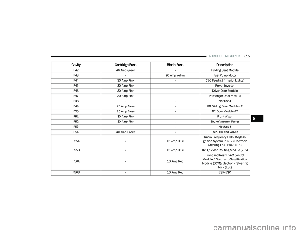
F42 40 Amp Green –Folding Seat Module
F43 –20 Amp Yellow Fuel Pump Motor
F44 30 Amp Pink –CBC Feed #1 (Interior Lights)
F45 30 Amp Pink –Power Inverter
F46 30 Amp Pink –Driver Door Module
F47 30 Amp Pink –Passenger Door Module
F48 ––Not Used
F49 25 Amp Clear –RR Sliding Door Module-LT
F50 25 Amp Clear –RR Door Module-RT
F51 30 Amp Pink –Front Wiper
F52 30 Amp Pink –Brake Vacuum Pump
F53 ––Not Used
F54 40 Amp Green –ESP-ECU And Valves
F55A –15 Amp BlueRadio Frequency HUB/ Keyless
Ignition System (KIN) / (Electronic Steering Lock-BUX ONLY)
F55B –15 Amp BlueDVD / Video Routing Module (VRM
F56A –10 Amp RedFront and Rear HVAC Control
Module / Occupant Classification
Module (OCM)/Electronic Steering Lock (ESL)
F56B –10 Amp Red ESP/ESC
CavityCartridge Fuse Blade FuseDescription
6
20_RU_OM_EN_US_t.book Page 315
Page 331 of 516
IN CASE OF EMERGENCY329
(Continued)
Whenever You Stop To Use Tire Service Kit:
1. Pull over to a safe location and turn on the vehicle’s Hazard Warning Flashers.
2. Verify that the valve stem (on the wheel with the deflated tire) is in a position that is near
to the ground. This will allow the Tire Service
Kit Hose to reach the valve stem and keep
the Tire Service Kit flat on the ground. This
will provide the best positioning of the kit
when running the air pump. Move the
vehicle as necessary to place the valve
stem in this position before proceeding.
3. Place the transmission in PARK (P) and cycle the ignition in the OFF position.
4. Ensure the park brake is engaged. Setting Up To Use Tire Service Kit:
1. Remove the Tire Service Kit from the
storage location.
2. Uncoil the Sealant/Air Hose.
Remove the cap from the valve stem
and then screw the fitting in at the
end of the Sealant/Air Hose clockwise
onto the valve stem.
3. Place the Tire Service Kit on the ground next
to the deflated tire.
4. Uncoil the Power Plug and insert
the plug into the vehicle’s 12 Volt
power outlet.
5. Engage parking brake before turning the
engine ON. 6. Always start the engine before
turning ON the Tire Service Kit.
7. Turn the Mode Select Knob to Air
Mode position.
WARNING!
Keep Tire Service Kit away from open
flames or heat source.
A loose Tire Service Kit thrown forward in a
collision or hard stop could endanger the
occupants of the vehicle. Always stow the
Tire Service Kit in the place provided.
Failure to follow these warnings can result
in injuries that are serious or fatal to you,
your passengers, and others around you.
Take care not to allow the contents of Tire
Service Kit to come in contact with hair, eyes,
or clothing. Tire Service Kit sealant is
harmful if inhaled, swallowed, or absorbed
through the skin. It causes skin, eye, and
respiratory irritation. Flush immediately with
plenty of water if there is any contact with
eyes or skin. Change clothing as soon as
possible, if there is any contact with clothing.
Tire Service Kit Sealant solution contains
latex. In case of an allergic reaction or rash,
consult a physician immediately. Keep Tire
Service Kit out of reach of children. If swal -
lowed, rinse mouth immediately with plenty
of water and drink plenty of water. Do not
induce vomiting! Consult a physician imme -
diately.
WARNING! (Continued)
6
20_RU_OM_EN_US_t.book Page 329
Page 335 of 516
IN CASE OF EMERGENCY333
Sealing A Tire With Tire Service Kit
Whenever You Stop To Use Tire Service Kit:
1. Pull over to a safe location and turn on the
vehicle’s Hazard Warning flashers.
2. Verify that the valve stem (on the wheel with the deflated tire) is in a position that is near
to the ground. This will allow the Tire Service
Kit Hose to reach the valve stem and keep
the Tire Service Kit flat on the ground. This
will provide the best positioning of the kit
when injecting the sealant into the deflated
tire and running the air pump. Move the
vehicle as necessary to place the valve
stem in this position before proceeding.
3. Place the transmission in PARK (P) and cycle the ignition in the OFF position.
4. Apply the parking brake. Setting Up To Use Tire Service Kit:
1. Uncoil the Sealant Hose and then remove
the cap from the fitting at the end of the
hose.
2. Place the Tire Service Kit flat on the
ground next to the deflated tire.
3. Remove the cap from the valve stem and then screw the fitting at the end of the
Sealant Hose onto the valve stem.
4. Uncoil the Power Plug and insert
the plug into the vehicle’s 12 Volt
power outlet.
NOTE:
Do not remove foreign objects (e.g., screws or
nails) from the tire.
Take care not to allow the contents of Tire
Service Kit to come in contact with hair,
eyes, or clothing. Tire Service Kit sealant is
harmful if inhaled, swallowed, or absorbed
through the skin. It causes skin, eye, and
respiratory irritation. Flush immediately
with plenty of water if there is any contact
with eyes or skin. Change clothing as soon
as possible, if there is any contact with
clothing.
Tire Service Kit Sealant solution contains
latex. In case of an allergic reaction or rash,
consult a physician immediately. Keep Tire
Service Kit out of reach of children. If swal -
lowed, rinse mouth immediately with plenty
of water and drink plenty of water. Do not
induce vomiting! Consult a physician imme -
diately.
WARNING! (Continued)
6
20_RU_OM_EN_US_t.book Page 333