engine CHRYSLER VOYAGER 2020 Repair Manual
[x] Cancel search | Manufacturer: CHRYSLER, Model Year: 2020, Model line: VOYAGER, Model: CHRYSLER VOYAGER 2020Pages: 516, PDF Size: 28.69 MB
Page 236 of 516
![CHRYSLER VOYAGER 2020 Repair Manual
234STARTING AND OPERATING
NOTE:
The torque converter clutch will not engage until
the engine and/or transmission is warm
(usually after 1 to 3 miles [2 to 5 km] of driving).
Because the engine s CHRYSLER VOYAGER 2020 Repair Manual
234STARTING AND OPERATING
NOTE:
The torque converter clutch will not engage until
the engine and/or transmission is warm
(usually after 1 to 3 miles [2 to 5 km] of driving).
Because the engine s](/img/25/40537/w960_40537-235.png)
234STARTING AND OPERATING
NOTE:
The torque converter clutch will not engage until
the engine and/or transmission is warm
(usually after 1 to 3 miles [2 to 5 km] of driving).
Because the engine speed is higher when the
torque converter clutch is not engaged, it may
seem as if the transmission is not shifting prop -
erly when the vehicle is cold. This is normal. The
torque converter clutch will function normally
once the powertrain is sufficiently warm.
ACTIVE NOISE CANCELLATION
Your vehicle is equipped with an Active Noise
Cancellation System. This system is designed
to address exhaust and engine noise. The
system relies on four microphones embedded
in the headliner, which monitor exhaust and
engine noise, and assists an onboard
frequency generator, which creates
counteracting sound waves in the audio
system’s speakers. This helps keep the vehicle
quiet at idle and during drive.
POWER STEERING
The electric power steering system will give you
good vehicle response and increased ease of
maneuverability in tight spaces. The system will
vary its assist to provide light efforts while
parking and good feel while driving. If the
electric steering system experiences a fault that
reduces assist or prevents the vehicle from
providing assist, you will still have the ability to
steer the vehicle manually.
If the Steering icon is displayed and the
“POWER STEERING SYSTEM OVER TEMP”
message is displayed on the instrument cluster
screen, they indicate that extreme steering
maneuvers may have occurred which caused
an over temperature condition in the power
steering system. Once driving conditions are
safe, pull over and let the vehicle idle for a few moments until the icon and message turn off.
Refer to “Instrument Cluster Display” in
“Getting To Know Your Instrument Panel” for
further information.
If the “SERVICE POWER STEERING"
OR "POWER STEERING ASSIST OFF -
SERVICE SYSTEM” message and a
steering wheel icon are displayed on
the instrument cluster screen, it indicates that
the vehicle needs to be taken to the dealer for
service. It is likely the vehicle has lost power
steering assistance. Refer to “Warning Lights
And Messages” in “Getting To Know Your
Instrument Panel” for further information.
NOTE:
Even if the power steering assistance is no
longer operational, it is still possible to steer
the vehicle. Under these conditions there will
be a substantial increase in steering effort,
especially at low speeds and during parking
maneuvers.
The power steering system is fully electric; it
requires no power steering fluid.
If the condition persists, see an authorized
dealer for service.
WARNING!
Continued operation with reduced assist
could pose a safety risk to yourself and
others. Service should be obtained as soon
as possible.
20_RU_OM_EN_US_t.book Page 234
Page 237 of 516
STARTING AND OPERATING235
STOP/START SYSTEM — IF EQUIPPED
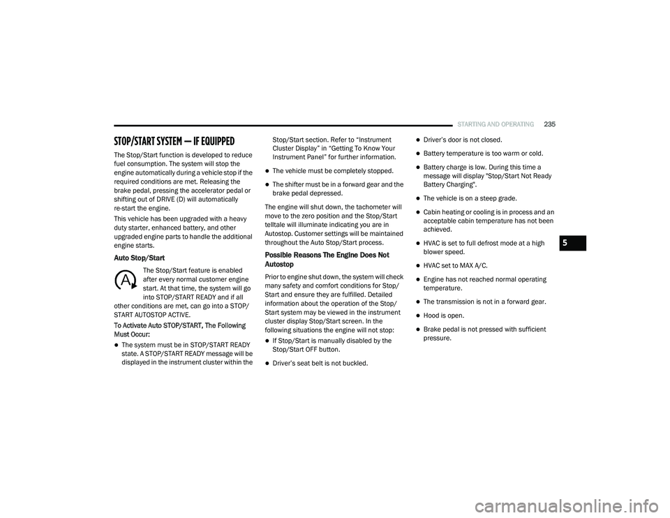
The Stop/Start function is developed to reduce
fuel consumption. The system will stop the
engine automatically during a vehicle stop if the
required conditions are met. Releasing the
brake pedal, pressing the accelerator pedal or
shifting out of DRIVE (D) will automatically
re-start the engine.
This vehicle has been upgraded with a heavy
duty starter, enhanced battery, and other
upgraded engine parts to handle the additional
engine starts.
Auto Stop/Start
The Stop/Start feature is enabled
after every normal customer engine
start. At that time, the system will go
into STOP/START READY and if all
other conditions are met, can go into a STOP/
START AUTOSTOP ACTIVE.
To Activate Auto STOP/START, The Following
Must Occur:
The system must be in STOP/START READY
state. A STOP/START READY message will be
displayed in the instrument cluster within the Stop/Start section. Refer to “Instrument
Cluster Display” in “Getting To Know Your
Instrument Panel” for further information.
The vehicle must be completely stopped.
The shifter must be in a forward gear and the
brake pedal depressed.
The engine will shut down, the tachometer will
move to the zero position and the Stop/Start
telltale will illuminate indicating you are in
Autostop. Customer settings will be maintained
throughout the Auto Stop/Start process.
Possible Reasons The Engine Does Not
Autostop
Prior to engine shut down, the system will check
many safety and comfort conditions for Stop/
Start and ensure they are fulfilled. Detailed
information about the operation of the Stop/
Start system may be viewed in the instrument
cluster display Stop/Start screen. In the
following situations the engine will not stop:
If Stop/Start is manually disabled by the
Stop/Start OFF button.
Driver’s seat belt is not buckled.
Driver’s door is not closed.
Battery temperature is too warm or cold.
Battery charge is low. During this time a
message will display "Stop/Start Not Ready
Battery Charging".
The vehicle is on a steep grade.
Cabin heating or cooling is in process and an
acceptable cabin temperature has not been
achieved.
HVAC is set to full defrost mode at a high
blower speed.
HVAC set to MAX A/C.
Engine has not reached normal operating
temperature.
The transmission is not in a forward gear.
Hood is open.
Brake pedal is not pressed with sufficient
pressure.
5
20_RU_OM_EN_US_t.book Page 235
Page 238 of 516

236STARTING AND OPERATING
Other Factors Which Can Inhibit Autostop
Include:
Accelerator pedal input.
Engine temp too high.
5 mph (8 km/h) threshold not achieved from
previous AUTOSTOP.
Steering angle beyond threshold.
ACC is on and speed is set.
It may be possible for the vehicle to be driven
several times without the Stop/Start system
going into a Stop/Start READY state under more
extreme conditions of the items listed above.
To Start The Engine While In Auto Stop/Start
While in a forward gear, the engine will start
when the brake pedal is released or the throttle
pedal is depressed. The transmission will
automatically re-engage upon engine restart.
Conditions That Will Cause The Engine To Start
Automatically While In Auto Stop/Start:
The transmission selector is moved out of
DRIVE.
To maintain cabin temperature comfort.
HVAC is set to full defrost mode.
HVAC system temperature or fan speed is
manually adjusted.
Battery voltage drops too low. During this
time a message will display "Stop/Start Not
Ready Battery Charging".
Low brake vacuum (e.g. after several brake
pedal applications).
Stop/Start OFF switch is pushed.
A Stop/Start system error occurs.
To Manually Turn Off The Stop/Start System
Stop/Start OFF Button
1. Push the Stop/Start OFF switch (located on
the instrument panel). The light on the
switch will illuminate.
2. The “STOP/START OFF” message will appear in the instrument cluster display.
Refer to “Instrument Cluster Display” in
“Getting To Know Your Instrument Panel”
for further information.
3. At the next vehicle stop (after turning off the Stop/Start system) the engine will not be
stopped.
4. The Stop/Start system will reset itself back to an ON condition every time the ignition is
turned off and back on.
Automatic Shutdown
This vehicle is equipped with an automatic
shutdown feature. If the vehicle is left in READY
mode (vehicle running) with the gear selector in
PARK for one hour after the driver exits, this
feature will automatically turn the vehicle off.
Notifications have been added into this feature
to raise awareness of the timed event:In the interior of the vehicle, the instrument
cluster will display “Ready To Drive”, and will
be accompanied by three audible chimes
20_RU_OM_EN_US_t.book Page 236
Page 239 of 516
STARTING AND OPERATING237
while exiting. These interior warnings will
occur regardless of whether the key fob
remains in the vehicle or is removed.
For the exterior of the vehicle, the horn will
sound three times if the fob is removed from
the vehicle and the vehicle is in the “READY”
mode.
Please consider this feature when intentionally
running the vehicle for extended periods of time
over one hour. To restart the vehicle, follow the
normal vehicle starting process.
NOTE:
If the vehicle is left in the ACC or RUN (engine
not running) position and the transmission is in
PARK, the system will automatically time out
(shut down) after an initial 30 minutes of inac -
tivity, followed by the additional amount of time
for power accessory delay selected in the radio
settings menu. Once the vehicle times out, it will
switch to the OFF position.
To Manually Turn On The Stop/Start System
After turning off the Stop/Start system, push
the Stop/Start OFF switch again (located on the
instrument panel). The light on the switch will
turn off.
System Malfunction
If there is a malfunction in the Stop/Start
system, the system will not shut down the
engine. A “SERVICE STOP/START SYSTEM”
message will appear in the instrument cluster
display and the Stop/Start telltale will remain
yellow. Refer to “Instrument Cluster Display” in
“Getting To Know Your Instrument Panel” for
further information.
If the “SERVICE STOP/START SYSTEM”
message appears in the instrument cluster
display, have the system checked by an
authorized dealer.
SPEED CONTROL — IF EQUIPPED
When engaged, the Speed Control takes over
accelerator operations at speeds greater than
25 mph (40 km/h).
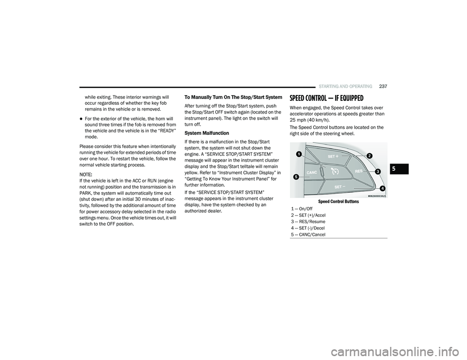
The Speed Control buttons are located on the
right side of the steering wheel.
Speed Control Buttons
1 — On/Off
2 — SET (+)/Accel
3 — RES/Resume
4 — SET (-)/Decel
5 — CANC/Cancel
5
20_RU_OM_EN_US_t.book Page 237
Page 288 of 516

286STARTING AND OPERATING
(Continued)
Rear Cross Path ViewPressing the Rear Cross Path soft key
will give the driver a wider angle view of
the rear camera system. The Top view
will be disabled when this is selected
Front View The Front view will show you what is
immediately in front of the vehicle and
is always paired with the Top view of
the vehicle.
Front Cross Path View
Pressing the Front Cross Path soft key will
give the driver a wider angle view of the
front camera system. The Top view will be
disabled when this is selected.
Deactivation
The system can be deactivated in the following
conditions:
The speed of the vehicle reaches greater
than 8 mph (13 km/h).
The vehicle shifted into PARK from a different
gear.
If the vehicle is in any gear other than
REVERSE, press the “X” button.
The camera delay system is turned off manu -
ally through the Uconnect settings menu.
Refer to “Uconnect Settings” in “Multimedia”
for further information.
NOTE:
If snow, ice, mud, or any foreign substance
builds up on the camera lenses, clean the
lenses, rinse with water, and dry with a soft
cloth. Do not cover the lenses.
If a malfunction with the system has
occurred, see an authorized dealer.REFUELING THE VEHICLE
There is no fuel filler cap. Two flapper doors
inside the pipe seal the system.
WARNING!
Drivers must be careful when backing up even
when using the Surround View Camera. Always
check carefully behind your vehicle, and be
sure to check for pedestrians, animals, other
vehicles, obstructions, or blind spots before
backing up. You are responsible for the safety
of your surroundings and must continue to pay
attention while backing up. Failure to do so can
result in serious injury or death.
CAUTION!
To avoid vehicle damage, Surround View
should only be used as a parking aid. The
Surround View camera is unable to view
every obstacle or object in your drive path.
To avoid vehicle damage, the vehicle must
be driven slowly when using Surround View
to be able to stop in time when an obstacle
is seen. It is recommended that the driver
look frequently over his/her shoulder when
using Surround View.
WARNING!
Never have any smoking materials lit in or
near the vehicle when the fuel door is open
or the tank is being filled.
Never add fuel when the engine is running.
This is in violation of most state and federal
fire regulations and may cause the
“Malfunction Indicator Light” to turn on.
20_RU_OM_EN_US_t.book Page 286
Page 292 of 516
290STARTING AND OPERATING
Tongue Weight (TW)
The tongue weight is the downward force
exerted on the hitch ball by the trailer. You must
consider this as part of the load on your vehicle.
Trailer Frontal Area
The frontal area is the maximum height
multiplied by the maximum width of the front of
a trailer.
Trailer Sway Control
The Trailer Sway Control can be a mechanical
telescoping link that can be installed between
the hitch receiver and the trailer tongue that
typically provides adjustable friction associated
with the telescoping motion to dampen any
unwanted trailer swaying motions while
traveling.
If equipped, the electronic Trailer Sway Control
(TSC) recognizes a swaying trailer and
automatically applies individual wheel brakes
and/or reduces engine power to attempt to
eliminate the trailer sway.
Weight-Carrying Hitch
A weight-carrying hitch supports the trailer
tongue weight, just as if it were luggage located
at a hitch ball or some other connecting point of
the vehicle. These kinds of hitches are the most
popular on the market today and they are
commonly used to tow small and medium sized
trailers.
Weight-Distributing Hitch
A weight-distributing system works by applying
leverage through spring (load) bars. They are
typically used for heavier loads to distribute
trailer tongue weight to the tow vehicle's front
axle and the trailer axle(s). When used in
accordance with the manufacturer's directions,
it provides for a more level ride, offering more
consistent steering and brake control thereby
enhancing towing safety. The addition of a
friction/hydraulic sway control also dampens
sway caused by traffic and crosswinds and
contributes positively to tow vehicle and trailer stability. Trailer sway control and a weight
distributing (load equalizing) hitch are
recommended for heavier Tongue Weights (TW)
and may be required depending on vehicle and
trailer configuration/loading to comply with
Gross Axle Weight Rating (GAWR) requirements.
WARNING!
An improperly adjusted Weight Distributing
Hitch system may reduce handling,
stability, braking performance, and could
result in a collision.
Weight Distributing Systems may not be
compatible with Surge Brake Couplers.
Consult with your hitch and trailer manufac
-
turer or a reputable Recreational Vehicle
dealer for additional information.
20_RU_OM_EN_US_t.book Page 290
Page 293 of 516
STARTING AND OPERATING291
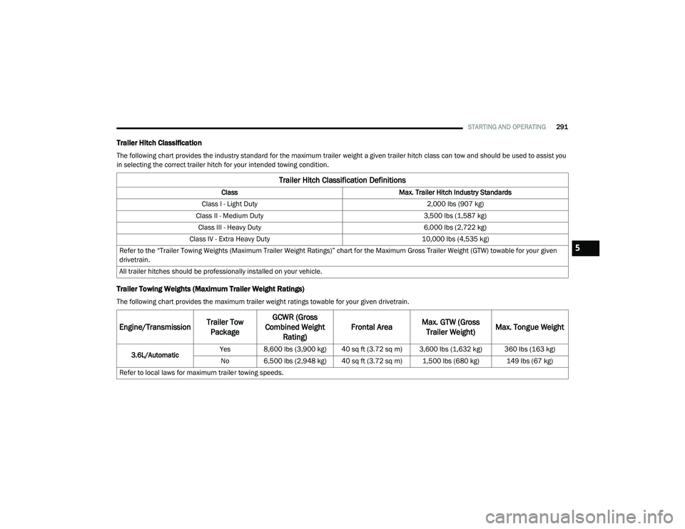
Trailer Hitch Classification
The following chart provides the industry standard for the maximum trailer weight a given trailer hitch class can tow and should be used to assist you
in selecting the correct trailer hitch for your intended towing condition.
Trailer Towing Weights (Maximum Trailer Weight Ratings)
The following chart provides the maximum trailer weight ratings towable for your given drivetrain.
Trailer Hitch Classification Definitions
Class Max. Trailer Hitch Industry Standards
Class I - Light Duty 2,000 lbs (907 kg)
Class II - Medium Duty 3,500 lbs (1,587 kg)
Class III - Heavy Duty 6,000 lbs (2,722 kg)
Class IV - Extra Heavy Duty 10,000 lbs (4,535 kg)
Refer to the “Trailer Towing Weights (Maximum Trailer Weight Ratings)” chart for the Maximum Gross Trailer Weight (GTW) towable for your given
drivetrain.
All trailer hitches should be professionally installed on your vehicle.
Engine/Transmission Trailer Tow
Package GCWR (Gross
Combined Weight Rating) Frontal Area
Max. GTW (Gross
Trailer Weight) Max. Tongue Weight
3.6L/Automatic Yes 8,600 lbs (3,900 kg) 40 sq ft (3.72 sq m) 3,600 lbs (1,632 kg) 360 lbs (163 kg)
No 6,500 lbs (2,948 kg) 40 sq ft (3.72 sq m) 1,500 lbs (680 kg) 149 lbs (67 kg)
Refer to local laws for maximum trailer towing speeds.
5
20_RU_OM_EN_US_t.book Page 291
Page 296 of 516
294STARTING AND OPERATING
(Continued)
Make sure loading does not exceed GAWR of
front or rear axles.
GAWR is found on sticker in Driver’s Side
Door Jamb.
Trailer And Tongue Weight
Never exceed the maximum tongue weight
stamped on your bumper or trailer hitch.
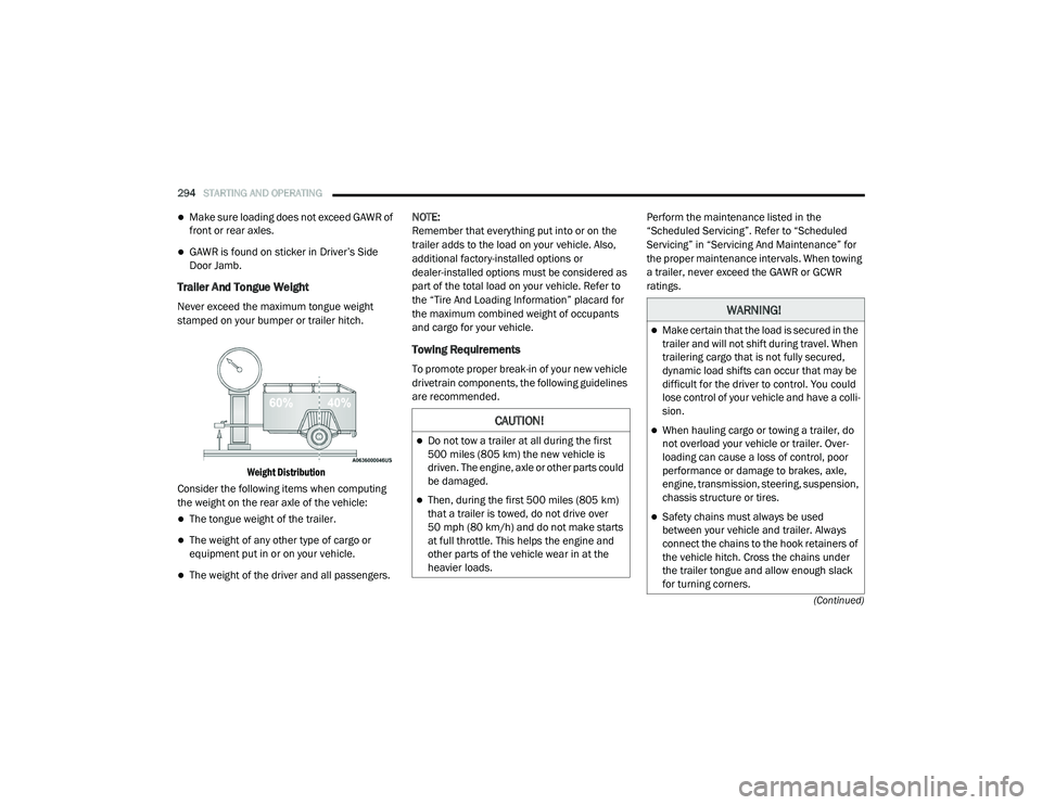
Weight Distribution
Consider the following items when computing
the weight on the rear axle of the vehicle:
The tongue weight of the trailer.
The weight of any other type of cargo or
equipment put in or on your vehicle.
The weight of the driver and all passengers. NOTE:
Remember that everything put into or on the
trailer adds to the load on your vehicle. Also,
additional factory-installed options or
dealer-installed options must be considered as
part of the total load on your vehicle. Refer to
the “Tire And Loading Information” placard for
the maximum combined weight of occupants
and cargo for your vehicle.
Towing Requirements
To promote proper break-in of your new vehicle
drivetrain components, the following guidelines
are recommended.
Perform the maintenance listed in the
“Scheduled Servicing”. Refer to “Scheduled
Servicing” in “Servicing And Maintenance” for
the proper maintenance intervals. When towing
a trailer, never exceed the GAWR or GCWR
ratings.
CAUTION!
Do not tow a trailer at all during the first
500 miles (805 km) the new vehicle is
driven. The engine, axle or other parts could
be damaged.
Then, during the first 500 miles (805 km) that a trailer is towed, do not drive over
50 mph (80 km/h) and do not make starts
at full throttle. This helps the engine and
other parts of the vehicle wear in at the
heavier loads.
WARNING!
Make certain that the load is secured in the
trailer and will not shift during travel. When
trailering cargo that is not fully secured,
dynamic load shifts can occur that may be
difficult for the driver to control. You could
lose control of your vehicle and have a colli -
sion.
When hauling cargo or towing a trailer, do
not overload your vehicle or trailer. Over -
loading can cause a loss of control, poor
performance or damage to brakes, axle,
engine, transmission, steering, suspension,
chassis structure or tires.
Safety chains must always be used
between your vehicle and trailer. Always
connect the chains to the hook retainers of
the vehicle hitch. Cross the chains under
the trailer tongue and allow enough slack
for turning corners.
20_RU_OM_EN_US_t.book Page 294
Page 299 of 516
STARTING AND OPERATING297
Towing Tips
Before setting out on a trip, practice turning,
stopping, and backing up the trailer in an area
located away from heavy traffic.
Automatic Transmission
Select the DRIVE range when towing. The
transmission controls include a drive strategy to
avoid frequent shifting when towing. For
increased engine braking on steep downhill
grades, select the LOW range.
Speed Control — If Equipped
Do not use on hilly terrain or with heavy
loads.
When using the Speed Control, if you experi -
ence speed drops greater than 10 mph
(16 km/h), disengage until you can get back
to cruising speed.
Use Speed Control in flat terrain and with
light loads to maximize fuel efficiency.
Cooling System
To reduce potential for engine and transmission
overheating, take the following actions:
City Driving
In city traffic — while stopped, place the
transmission in NEUTRAL (N), but do not
increase engine idle speed.
Highway Driving
Reduce speed.
Temporarily turn off air conditioning.
5
20_RU_OM_EN_US_t.book Page 297
Page 302 of 516
300STARTING AND OPERATING
(Continued)
(Continued)
Flowing/Rising Water
Shallow Standing Water
Although your vehicle is capable of driving
through shallow standing water, consider the
following Warnings and Cautions before doing so.
WARNING!
Do not drive on or across a road or path
where water is flowing and/or rising (as in
storm run-off). Flowing water can wear away
the road or path's surface and cause your
vehicle to sink into deeper water.
Furthermore, flowing and/or rising water can
carry your vehicle away swiftly. Failure to
follow this warning may result in injuries that
are serious or fatal to you, your passengers,
and others around you.
WARNING!
Driving through standing water limits your
vehicle’s traction capabilities. Do not
exceed 5 mph (8 km/h) when driving
through standing water.
Driving through standing water limits your
vehicle’s braking capabilities, which
increases stopping distances. Therefore,
after driving through standing water, drive
slowly and lightly press on the brake pedal
several times to dry the brakes.
Failure to follow these warnings may result
in injuries that are serious or fatal to you,
your passengers, and others around you.
CAUTION!
Always check the depth of the standing
water before driving through it. Never drive
through standing water that is deeper than
the bottom of the tire rims mounted on the
vehicle.
Determine the condition of the road or the
path that is under water and if there are any
obstacles in the way before driving through
the standing water.
WARNING! (Continued)
Do not exceed 5 mph (8 km/h) when
driving through standing water. This will
minimize wave effects.
Driving through standing water may cause
damage to your vehicle’s drivetrain compo -
nents. Always inspect your vehicle’s fluids
(i.e., engine oil, transmission, axle, etc.) for
signs of contamination (i.e., fluid that is
milky or foamy in appearance) after driving
through standing water. Do not continue to
operate the vehicle if any fluid appears
contaminated, as this may result in further
damage. Such damage is not covered by
the New Vehicle Limited Warranty.
Getting water inside your vehicle’s engine
can cause it to lock up and stall out, and
cause serious internal damage to the
engine. Such damage is not covered by the
New Vehicle Limited Warranty.
CAUTION! (Continued)
20_RU_OM_EN_US_t.book Page 300