engine CHRYSLER VOYAGER 2020 Manual PDF
[x] Cancel search | Manufacturer: CHRYSLER, Model Year: 2020, Model line: VOYAGER, Model: CHRYSLER VOYAGER 2020Pages: 516, PDF Size: 28.69 MB
Page 313 of 516
IN CASE OF EMERGENCY311
(Continued)
4. Remove/replace bulb(s).
5. Reinstall the socket(s).
6. Reverse process to reinstall the liftgate trim.
Rear Bodyside Mounted Taillamps
1. Raise the liftgate.
2. Remove two torx head screws on the bodyside lamp using a T30 screwdriver.
3. Remove lamp from vehicle body and locate bulb socket on rear of lamp. Rotate socket
counterclockwise.
4. Remove/replace bulb(s).
5. Reinstall the socket(s).
6. Reverse process to reinstall the lamp onto vehicle.
Center High Mounted Stop Lamp (CHMSL)
The center high-mounted stop lamp is an LED
assembly. See an authorized dealer for
replacement.
Rear License Lamp
The rear license lamps are LED. See an
authorized dealer for replacement.
FUSES
General Information
The fuses protect electrical systems against
excessive current.
When a device does not work, you must check
the fuse element inside the blade fuse for a
break/melt.
WARNING!
When replacing a blown fuse, always use
an appropriate replacement fuse with the
same amp rating as the original fuse. Never
replace a fuse with another fuse of higher
amp rating. Never replace a blown fuse with
metal wires or any other material. Do not
place a fuse inside a circuit breaker cavity
or vice versa. Failure to use proper fuses
may result in serious personal injury, fire
and/or property damage.
Before replacing a fuse, make sure that the
ignition is off and that all the other services
are switched off and/or disengaged.
If the replaced fuse blows again, contact an
authorized dealer.
If a general protection fuse for safety
systems (air bag system, braking system),
power unit systems (engine system, trans -
mission system) or steering system blows,
contact an authorized dealer.
WARNING! (Continued)
6
20_RU_OM_EN_US_t.book Page 311
Page 314 of 516
312IN CASE OF EMERGENCY
Also, please be aware that when using power
outlets for extended periods of time with the
engine off may result in vehicle battery
discharge.
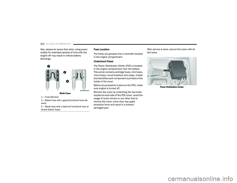
Blade Fuses
Fuse Location
The fuses are grouped into a controller located
in the engine compartment.
Underhood Fuses
The Power Distribution Center (PDC) is located
in the engine compartment near the battery.
This center contains cartridge fuses, mini-fuses,
micro-fuses, circuit breakers and relays. A label
that identifies each component is printed on the
inside of the cover.
Before any procedure is done on the PDC, make
sure engine is turned off.
Remove the cover by unlatching the two locks
located at each side of the PDC cover, avoid the
usage of screw drivers or any other tool to
remove the cover, since they may apply
excessive force and result in a broken/
damaged part. After service is done, secure the cover with its
two locks.
Power Distribution Center
1 — Fuse Element
2 — Blade Fuse with a good/functional fuse ele -
ment.
3 — Blade fuse with a bad/not functional fuse el -
ement (blown fuse).
20_RU_OM_EN_US_t.book Page 312
Page 329 of 516
IN CASE OF EMERGENCY327
(Continued)
Portable Air Compressor — If Equipped
Your vehicle may be equipped with a Portable
Air Compressor. Use the Portable Air
Compressor located in the side compartment of
the cargo area to inflate the inflatable tire to
60 psi (4.2 Bar).
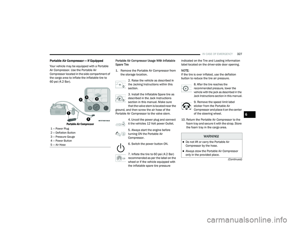
Portable Air Compressor
Portable Air Compressor Usage With Inflatable
Spare Tire
1. Remove the Portable Air Compressor from
the storage location.
2. Raise the vehicle as described in
the Jacking Instructions within this
section.
3. Install the Inflatable Spare tire as
described in the Jack Instructions
section in this manual. Make sure
that the valve stem is located near the
ground, and then screw the air hose of the
Portable Air Compressor to the valve stem.
4. Uncoil the power plug and connect
it the vehicles 12 Volt power Outlet.
5. Always start the engine before
turning ON the Portable Air
Compressor.
6. Switch the power button ON.
7. Inflate the tire to 60 psi (4.2 Bar)
recommended as per the label on the
wheel or if the vehicle equipped with
the inflatable spare tire pressure indicated on the Tire and Loading information
label located on the driver-side door opening.
NOTE:
If the tire is over inflated, use the deflation
button to reduce the tire air pressure.
8. After the tire reaches the
recommended pressure, lower the
vehicle with the jack as described in the
Jack Instructions section in this manual.
9. Remove the speed limit label
sticker from the Portable Air
Compressor and place it on the center
of the steering wheel.
10. Return the Portable Air Compressor to the foam tray and secure it with the strap. Store
the foam tray in the cargo area.
1 — Power Plug
2 — Deflation Button
3 — Pressure Gauge
4 — Power Button
5 — Air Hose
WARNING!
Do not lift or carry the Portable Air
Compressor by the hose.
Always stow the Portable Air Compressor
only in the provided place.
6
20_RU_OM_EN_US_t.book Page 327
Page 331 of 516
IN CASE OF EMERGENCY329
(Continued)
Whenever You Stop To Use Tire Service Kit:
1. Pull over to a safe location and turn on the vehicle’s Hazard Warning Flashers.
2. Verify that the valve stem (on the wheel with the deflated tire) is in a position that is near
to the ground. This will allow the Tire Service
Kit Hose to reach the valve stem and keep
the Tire Service Kit flat on the ground. This
will provide the best positioning of the kit
when running the air pump. Move the
vehicle as necessary to place the valve
stem in this position before proceeding.
3. Place the transmission in PARK (P) and cycle the ignition in the OFF position.
4. Ensure the park brake is engaged. Setting Up To Use Tire Service Kit:
1. Remove the Tire Service Kit from the
storage location.
2. Uncoil the Sealant/Air Hose.
Remove the cap from the valve stem
and then screw the fitting in at the
end of the Sealant/Air Hose clockwise
onto the valve stem.
3. Place the Tire Service Kit on the ground next
to the deflated tire.
4. Uncoil the Power Plug and insert
the plug into the vehicle’s 12 Volt
power outlet.
5. Engage parking brake before turning the
engine ON. 6. Always start the engine before
turning ON the Tire Service Kit.
7. Turn the Mode Select Knob to Air
Mode position.
WARNING!
Keep Tire Service Kit away from open
flames or heat source.
A loose Tire Service Kit thrown forward in a
collision or hard stop could endanger the
occupants of the vehicle. Always stow the
Tire Service Kit in the place provided.
Failure to follow these warnings can result
in injuries that are serious or fatal to you,
your passengers, and others around you.
Take care not to allow the contents of Tire
Service Kit to come in contact with hair, eyes,
or clothing. Tire Service Kit sealant is
harmful if inhaled, swallowed, or absorbed
through the skin. It causes skin, eye, and
respiratory irritation. Flush immediately with
plenty of water if there is any contact with
eyes or skin. Change clothing as soon as
possible, if there is any contact with clothing.
Tire Service Kit Sealant solution contains
latex. In case of an allergic reaction or rash,
consult a physician immediately. Keep Tire
Service Kit out of reach of children. If swal -
lowed, rinse mouth immediately with plenty
of water and drink plenty of water. Do not
induce vomiting! Consult a physician imme -
diately.
WARNING! (Continued)
6
20_RU_OM_EN_US_t.book Page 329
Page 339 of 516
IN CASE OF EMERGENCY337
JUMP STARTING
If your vehicle has a discharged battery it can be
jump started using a set of jumper cables and a
battery in another vehicle or by using a portable
battery booster pack. Jump starting can be
dangerous if done improperly so please follow
the procedures in this section carefully.
NOTE:
When using a portable battery booster pack
follow the manufacturer’s operating instruc -
tions and precautions.
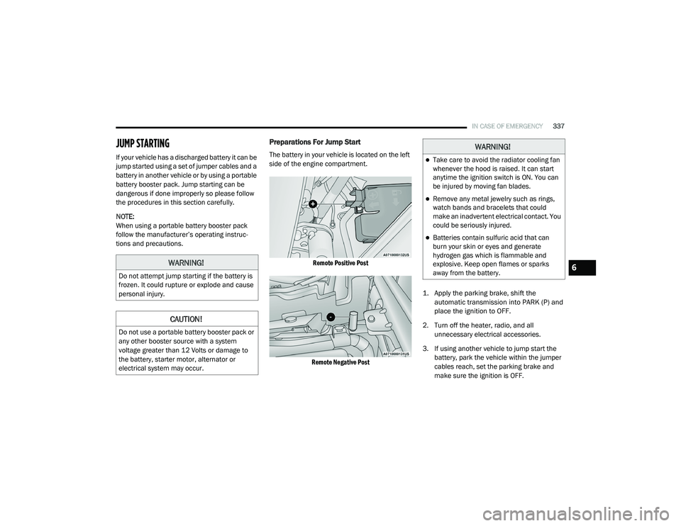
Preparations For Jump Start
The battery in your vehicle is located on the left
side of the engine compartment.
Remote Positive Post
Remote Negative Post
1. Apply the parking brake, shift the
automatic transmission into PARK (P) and
place the ignition to OFF.
2. Turn off the heater, radio, and all unnecessary electrical accessories.
3. If using another vehicle to jump start the battery, park the vehicle within the jumper
cables reach, set the parking brake and
make sure the ignition is OFF.
WARNING!
Do not attempt jump starting if the battery is
frozen. It could rupture or explode and cause
personal injury.
CAUTION!
Do not use a portable battery booster pack or
any other booster source with a system
voltage greater than 12 Volts or damage to
the battery, starter motor, alternator or
electrical system may occur.
WARNING!
Take care to avoid the radiator cooling fan
whenever the hood is raised. It can start
anytime the ignition switch is ON. You can
be injured by moving fan blades.
Remove any metal jewelry such as rings,
watch bands and bracelets that could
make an inadvertent electrical contact. You
could be seriously injured.
Batteries contain sulfuric acid that can
burn your skin or eyes and generate
hydrogen gas which is flammable and
explosive. Keep open flames or sparks
away from the battery.
6
20_RU_OM_EN_US_t.book Page 337
Page 340 of 516
338IN CASE OF EMERGENCY
Jump Starting Procedure
Connecting The Jumper Cables
1. Connect the positive
(+) end of the jumper
cable to the remote positive (+)
post of the
vehicle with the discharged battery.
2. Connect the opposite end of the positive (+)
jumper cable to the positive (+) post of the
booster battery. 3. Connect the negative
(-) end of the jumper
cable to the negative (-) post of the booster
battery.
4. Connect the opposite end of the negative (-)
jumper cable to the remote negative post
near the windshield cowl (exposed metal
part of the discharged vehicle’s engine).
5. Start the engine in the vehicle that has the booster battery, let the engine idle a few
minutes, and then start the engine in the
vehicle with the discharged battery.
6. Once the engine is started, remove the jumper cables in the reverse sequence. Disconnecting The Jumper Cables
1. Disconnect the negative
(-)
end of the jumper
cable from the remote negative post of the
vehicle with the discharged battery.
2. Disconnect the opposite end of the negative (-) jumper cable from the negative (-) post of
the booster battery.
3. Disconnect the positive (+) end of the
jumper cable from the positive (+) post of
the booster battery.
4. Disconnect the opposite end of the positive (+)
jumper cable from the remote positive (+) post
of the vehicle with the discharged battery.
If frequent jump starting is required to start your
vehicle you should have the battery and charging
system inspected at an authorized dealer.
WARNING!
Do not allow vehicles to touch each other as
this could establish a ground connection and
personal injury could result.
WARNING!
Failure to follow this jump starting procedure
could result in personal injury or property
damage due to battery explosion.
CAUTION!
Failure to follow these procedures could
result in damage to the charging system of
the booster vehicle or the discharged vehicle.
WARNING!
Do not connect the jumper cable to the
negative (-) post of the discharged battery. The
resulting electrical spark could cause the
battery to explode and could result in personal
injury. Only use the specific ground point, do
not use any other exposed metal parts.
CAUTION!
Accessories plugged into the vehicle power
outlets draw power from the vehicle’s battery,
even when not in use (i.e., cellular devices,
etc.). Eventually, if plugged in long enough
without engine operation, the vehicle’s battery
will discharge sufficiently to degrade battery
life and/or prevent the engine from starting.
20_RU_OM_EN_US_t.book Page 338
Page 341 of 516
IN CASE OF EMERGENCY339
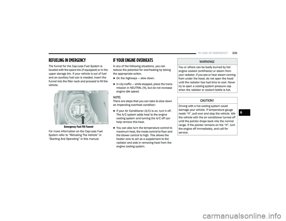
REFUELING IN EMERGENCY
The funnel for the Cap-Less Fuel System is
located with the spare tire (if equipped) or in the
upper storage bin. If your vehicle is out of fuel
and an auxiliary fuel can is needed, insert the
funnel into the filler neck and proceed to fill the
vehicle.
Emergency Fuel Fill Funnel
For more information on the Cap-Less Fuel
System refer to “Refueling The Vehicle” in
“Starting And Operating” in this manual.
IF YOUR ENGINE OVERHEATS
In any of the following situations, you can
reduce the potential for overheating by taking
the appropriate action.
On the highways — slow down.
In city traffic — while stopped, place the trans -
mission in NEUTRAL (N), but do not increase
engine idle speed.
NOTE:
There are steps that you can take to slow down
an impending overheat condition:
If your Air Conditioner (A/C) is on, turn it off.
The A/C system adds heat to the engine
cooling system and turning the A/C off can
help remove this heat.
You can also turn the temperature control to
maximum heat, the mode control to floor and
the blower control to high. This allows the
heater core to act as a supplement to the
radiator and aids in removing heat from the
engine cooling system.
WARNING!
You or others can be badly burned by hot
engine coolant (antifreeze) or steam from
your radiator. If you see or hear steam coming
from under the hood, do not open the hood
until the radiator has had time to cool. Never
try to open a cooling system pressure cap
when the radiator or coolant bottle is hot.
CAUTION!
Driving with a hot cooling system could
damage your vehicle. If temperature gauge
reads “H”, pull over and stop the vehicle. Idle
the vehicle with the air conditioner turned off
until the pointer drops back into the normal
range. If the pointer remains on the “H”, turn
the engine off immediately, and call for
service.
6
20_RU_OM_EN_US_t.book Page 339
Page 343 of 516
IN CASE OF EMERGENCY341
FREEING A STUCK VEHICLE
If your vehicle becomes stuck in mud, sand or
snow, it can often be moved using a rocking
motion. Turn the steering wheel right and left to
clear the area around the front wheels. Then
shift back and forth between DRIVE (D) and
REVERSE (R) while gently pressing the
accelerator.
NOTE:
Shifts between DRIVE and REVERSE can only be
achieved at wheel speeds of 5 mph (8 km/h) or
less. Whenever the transmission remains in
NEUTRAL (N) for more than two seconds, you
must press the brake pedal to engage DRIVE or
REVERSE.
Use the least amount of accelerator pedal
pressure that will maintain the rocking motion
without spinning the wheels or racing the
engine. NOTE:
Push the "ESC OFF" switch to place the Elec
-
tronic Stability Control (ESC) system in "Partial
Off" mode, before rocking the vehicle. Refer to
“Electronic Brake Control System” in “Safety”
for further information. Once the vehicle has
been freed, push the "ESC OFF" switch again to
restore "ESC On" mode.
WARNING!
Fast spinning tires can be dangerous. Forces
generated by excessive wheel speeds may
cause damage, or even failure, of the axle
and tires. A tire could explode and injure
someone. Do not spin your vehicle's wheels
faster than 30 mph (48 km/h) or for longer than 30 seconds continuously without
stopping when you are stuck and do not let
anyone near a spinning wheel, no matter
what the speed.
CAUTION!
Racing the engine or spinning the wheels
may lead to transmission overheating and
failure. Allow the engine to idle with the
transmission in NEUTRAL for at least one
minute after every five rocking-motion
cycles. This will minimize overheating and
reduce the risk of transmission failure
during prolonged efforts to free a stuck
vehicle.
When “rocking” a stuck vehicle by shifting
between DRIVE and REVERSE, do not spin
the wheels faster than 15 mph (24 km/h), or drivetrain damage may result.
Revving the engine or spinning the wheels
too fast may lead to transmission over -
heating and failure. It can also damage the
tires. Do not spin the wheels above 30 mph
(48 km/h) while in gear (no transmission
shifting occurring).
6
20_RU_OM_EN_US_t.book Page 341
Page 347 of 516
345
SERVICING AND MAINTENANCE
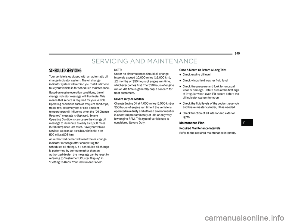
SCHEDULED SERVICING
Your vehicle is equipped with an automatic oil
change indicator system. The oil change
indicator system will remind you that it is time to
take your vehicle in for scheduled maintenance.
Based on engine operation conditions, the oil
change indicator message will illuminate. This
means that service is required for your vehicle.
Operating conditions such as frequent short-trips,
trailer tow, extremely hot or cold ambient
temperatures will influence when the “Oil Change
Required” message is displayed. Severe
Operating Conditions can cause the change oil
message to illuminate as early as 3,500 miles
(5,600 km) since last reset. Have your vehicle
serviced as soon as possible, within the next
500 miles (805 km).
An authorized dealer will reset the oil change
indicator message after completing the
scheduled oil change. If a scheduled oil change
is performed by someone other than an
authorized dealer, the message can be reset by
referring to “Instrument Cluster Display” in
“Getting To Know Your Instrument Panel”.NOTE:
Under no circumstances should oil change
intervals exceed 10,000 miles (16,000 km),
12 months or 350 hours of engine run time,
whichever comes first. The 350 hours of engine
run or idle time is generally only a concern for
fleet customers.
Severe Duty All Models
Change Engine Oil at 4,000 miles (6,500 km) or
350 hours of engine run time if the vehicle is
operated in a dusty and off road environment or
is operated predominately at idle or only very
low engine RPM. This type of vehicle use is
considered Severe Duty.
Once A Month Or Before A Long Trip:Check engine oil level
Check windshield washer fluid level
Check tire pressure and look for unusual
wear or damage. Rotate tires at the first sign
of irregular wear, even if it occurs before the
oil indicator system turns on
Check the fluid levels of the coolant reservoir
and brake master cylinder, fill as needed
Check function of all interior and exterior
lights
Maintenance Plan
Required Maintenance Intervals
Refer to the required maintenance intervals.
7
20_RU_OM_EN_US_t.book Page 345
Page 348 of 516
346SERVICING AND MAINTENANCE
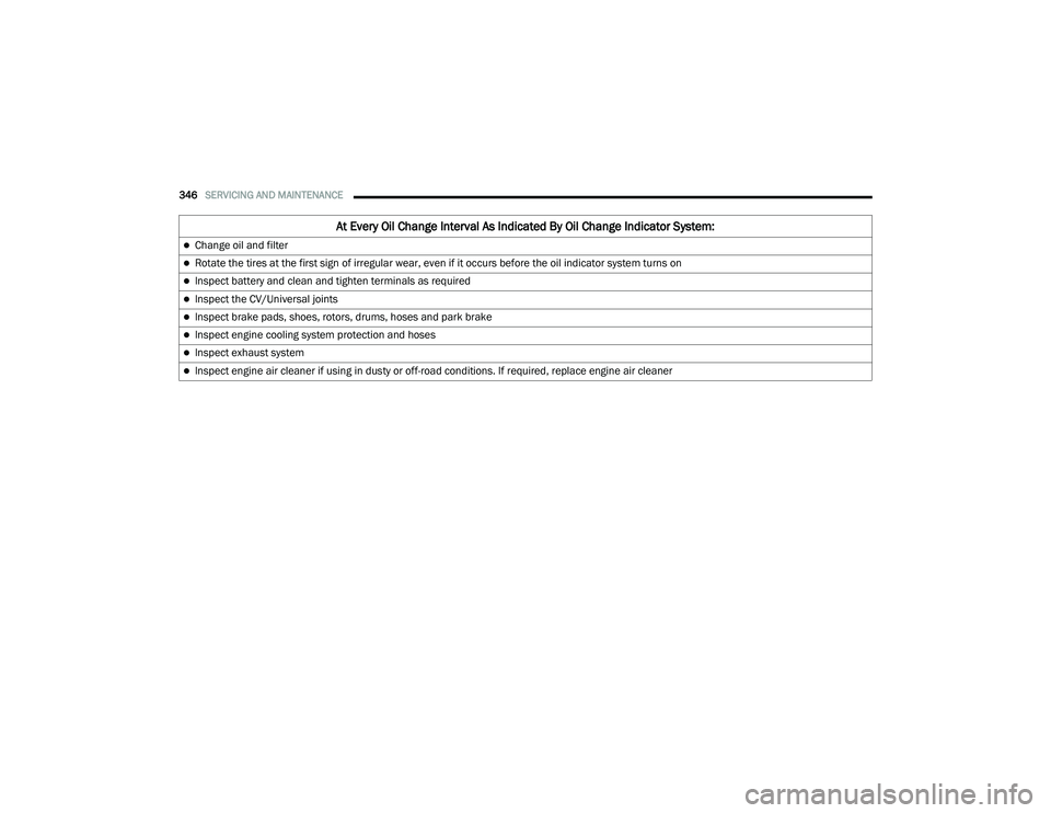
At Every Oil Change Interval As Indicated By Oil Change Indicator System:
Change oil and filter
Rotate the tires at the first sign of irregular wear, even if it occurs before the oil indicator system turns on
Inspect battery and clean and tighten terminals as required
Inspect the CV/Universal joints
Inspect brake pads, shoes, rotors, drums, hoses and park brake
Inspect engine cooling system protection and hoses
Inspect exhaust system
Inspect engine air cleaner if using in dusty or off-road conditions. If required, replace engine air cleaner
20_RU_OM_EN_US_t.book Page 346