battery location CHRYSLER VOYAGER 2021 Owners Manual
[x] Cancel search | Manufacturer: CHRYSLER, Model Year: 2021, Model line: VOYAGER, Model: CHRYSLER VOYAGER 2021Pages: 348, PDF Size: 18.73 MB
Page 5 of 348
3
EXTERIOR LIGHTS ................................................. 53 Multifunction Lever .........................................53
Headlight Switch...............................................53
Daytime Running Lights (DRLs) —
If Equipped........................................................54
High/Low Beam Switch....................................54
Flash-To-Pass ...................................................54
Automatic Headlights — If Equipped ..............54
Headlight Time Delay — If Equipped ...............54
Lights-On Reminder..........................................54
Front Fog Lights — If Equipped .......................54
Turn Signals ......................................................55
Lane Change Assist — If Equipped ..................55
Battery Protection ...........................................55
INTERIOR LIGHTS ................................................. 55
Interior Courtesy Lights ...................................55
WINDSHIELD WIPER AND WASHERS ............... 56
Windshield Wiper Operation .........................57
Rear Wiper And Washer ...................................58
CLIMATE CONTROLS ........................................... 58
Automatic Climate Control Descriptions
And Functions ...................................................58
Manual Climate Control Descriptions
And Functions ...................................................64
Automatic Temperature Control (ATC) —
If Equipped .......................................................69
Climate Voice Commands................................70
Operating Tips .................................................70 INTERIOR STORAGE AND EQUIPMENT ............... 71
Storage..............................................................71
Sun Screens — If Equipped..............................74
USB/AUX Control ...........................................75
Power Outlets ..................................................76
Cigar Lighter — If Equipped .............................78
Smoker's Package Kit — If Equipped .............78
WINDOWS ...............................................................78
Power Windows ................................................78
Automatic Window Features ...........................79
Reset Auto Up...................................................79
Wind Buffeting ..................................................80
HOOD .....................................................................80
Opening.............................................................80
Closing ..............................................................80
LIFTGATE ................................................................. 81
To Unlock/Open The Liftgate...........................81
To Lock/Close The Liftgate ..............................81
Power Liftgate — If Equipped ...........................81
Cargo Area Features .......................................82
STOW ‘N PLACE ROOF RACK —
IF EQUIPPED .......................................................... 83
Deploying The Crossbars .................................83
Stowing The Crossbars ....................................84
GETTING TO KNOW YOUR
INSTRUMENT PANEL
INSTRUMENT CLUSTER......................................... 87Instrument Cluster Descriptions ..................... 88
INSTRUMENT CLUSTER DISPLAY ....................... 88
Instrument Cluster Display Location And
Controls............................................................. 89
Oil Life Reset ................................................... 90
KeySense Cluster Messages —
If Equipped .......................................................90
Instrument Cluster Display Menu Items ........ 91
Battery Saver On/Battery Saver Mode
Message — Electrical Load Reduction
Actions — If Equipped ...................................... 95
TRIP COMPUTER ................................................... 96
WARNING LIGHTS AND MESSAGES ................... 97
Red Warning Lights ..........................................97
Yellow Warning Lights ................................... 100
Yellow Indicator Lights .................................. 103 Green Indicator Lights .................................. 103White Indicator Lights ................................... 103
Blue Indicator Lights ..................................... 103
ONBOARD DIAGNOSTIC SYSTEM — OBD II ..... 104
Onboard Diagnostic System
(OBD II) Cybersecurity ................................... 104
EMISSIONS INSPECTION AND MAINTENANCE
PROGRAMS ......................................................... 105
21_RUV_OM_EN_USC_t.book Page 3
Page 7 of 348
5
UCONNECT MODES ............................................. 159 Steering Wheel Audio Controls ................... 159
Radio Mode .................................................. 160
Media Mode .................................................. 168
Phone Mode ................................................. 170
ANDROID AUTO™ & APPLE CARPLAY® —
IF EQUIPPED ........................................................ 181
Android Auto™ .............................................. 181Apple CarPlay®.............................................. 183Android Auto™ And Apple CarPlay®
Tips And Tricks............................................... 185
RADIO OPERATION AND MOBILE PHONES ..... 185
Regulatory And Safety Information .............. 185
SAFETY
SAFETY FEATURES .............................................. 186Anti-Lock Brake System (ABS) ..................... 186
Electronic Brake Control (EBC) System ...... 187
AUXILIARY DRIVING SYSTEMS .......................... 192
Blind Spot Monitoring (BSM) —
If Equipped..................................................... 192
Forward Collision Warning (FCW)
With Mitigation — If Equipped....................... 196
Tire Pressure Monitoring System
(TPMS) ........................................................... 199 OCCUPANT RESTRAINT SYSTEMS ................... 202
Occupant Restraint Systems Features ....... 202
Important Safety Precautions ...................... 202Seat Belt Systems ........................................ 203Supplemental Restraint Systems (SRS) ...... 212Child Restraints ............................................ 225
SAFETY TIPS ...................................................... 241
Transporting Passengers .............................. 241Transporting Pets ........................................ 242Safety Checks You Should Make
Inside The Vehicle ........................................ 242Periodic Safety Checks You Should
Make Outside The Vehicle ............................ 243
Exhaust Gas ................................................. 244
Carbon Monoxide Warnings ........................ 244IN CASE OF EMERGENCY
HAZARD WARNING FLASHERS......................... 245
ASSIST AND SOS MIRROR —
IF EQUIPPED ....................................................... 245
JACKING AND TIRE CHANGING —
IF EQUIPPED ...................................................... 249
Preparations For Jacking ............................. 249
Jack And Spare Tire Location ....................... 250
Equipment Removal ..................................... 250
Jacking Instructions ..................................... 251
Road Tire Installation .................................... 254
Portable Air Compressor —
If Equipped..................................................... 255Return Inflatable Spare Tire ........................ 256 TIRE SERVICE KIT — IF EQUIPPED ..................... 257
JUMP STARTING .................................................. 262
Preparations For Jump Start ........................ 262Jump Starting Procedure .............................. 263
REFUELING IN EMERGENCY –
IF EQUIPPED ........................................................ 264
IF YOUR ENGINE OVERHEATS ............................ 265
MANUAL PARK RELEASE .................................. 266
FREEING A STUCK VEHICLE .............................. 267
TOWING A DISABLED VEHICLE ......................... 268
ENHANCED ACCIDENT RESPONSE
SYSTEM (EARS) ................................................... 270
EVENT DATA RECORDER (EDR) ......................... 270
SERVICING AND MAINTENANCE
SCHEDULED SERVICING .................................... 271 Maintenance Plan ......................................... 272
ENGINE COMPARTMENT ................................... 275
3.6L Engine ................................................... 275
Checking Oil Level ......................................... 276
Adding Washer Fluid .................................... 276
Maintenance-Free Battery ........................... 276
Pressure Washing ......................................... 277
21_RUV_OM_EN_USC_t.book Page 5
Page 18 of 348
16GETTING TO KNOW YOUR VEHICLE
(Continued)
The push button ignition can be placed in the
following modes:
OFF
The engine is stopped
Some electrical devices (e.g. power locks,
alarm, etc.) are still available
ACC
The engine is stopped
Some electrical devices are available (e.g.
power windows)
ON/RUN
Driving position
All the electrical devices are available (e.g.
climate controls, etc.)
START
The engine will start (when foot is on the brake
pedal)
The engine only runs in the ON/RUN ignition
position or from a Remote Start request.
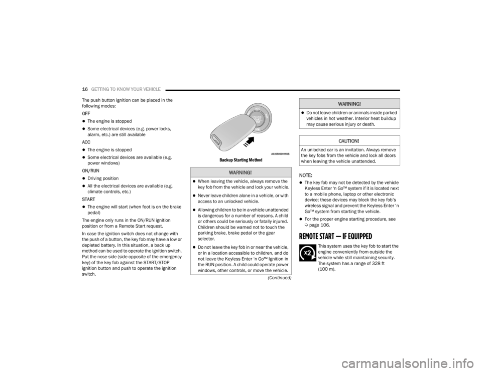
In case the ignition switch does not change with
the push of a button, the key fob may have a low or
depleted battery. In this situation, a back up
method can be used to operate the ignition switch.
Put the nose side (side opposite of the emergency
key) of the key fob against the START/STOP
ignition button and push to operate the ignition
switch.
Backup Starting Method
NOTE:
The key fob may not be detected by the vehicle
Keyless Enter ‘n Go™ system if it is located next
to a mobile phone, laptop or other electronic
device; these devices may block the key fob’s
wireless signal and prevent the Keyless Enter ‘n
Go™ system from starting the vehicle.
For the proper engine starting procedure, see Úpage 106.
REMOTE START — IF EQUIPPED
This system uses the key fob to start the
engine conveniently from outside the
vehicle while still maintaining security.
The system has a range of 328 ft
(100 m).
WARNING!
When leaving the vehicle, always remove the
key fob from the vehicle and lock your vehicle.
Never leave children alone in a vehicle, or with
access to an unlocked vehicle.
Allowing children to be in a vehicle unattended
is dangerous for a number of reasons. A child
or others could be seriously or fatally injured.
Children should be warned not to touch the
parking brake, brake pedal or the gear
selector.
Do not leave the key fob in or near the vehicle,
or in a location accessible to children, and do
not leave the Keyless Enter ‘n Go™ Ignition in
the RUN position. A child could operate power
windows, other controls, or move the vehicle.
Do not leave children or animals inside parked
vehicles in hot weather. Interior heat buildup
may cause serious injury or death.
CAUTION!
An unlocked car is an invitation. Always remove
the key fobs from the vehicle and lock all doors
when leaving the vehicle unattended.
WARNING!
21_RUV_OM_EN_USC_t.book Page 16
Page 22 of 348
20GETTING TO KNOW YOUR VEHICLE
NOTE:
The driver's door key cylinder and the liftgate
button on the key fob cannot arm or disarm the
Vehicle Security system.
The Vehicle Security system remains armed
during power liftgate entry. Pushing the liftgate
button will not disarm the Vehicle Security
system. If someone enters the vehicle through
the liftgate and opens any door, the alarm will
sound.
When the Vehicle Security system is armed, the
interior power door lock switches will not unlock
the doors.
The Vehicle Security system is designed to protect
your vehicle. However, you can create conditions
where the system will give you a false alarm. If one
of the previously described arming sequences has
occurred, the Vehicle Security system will arm
regardless of whether you are in the vehicle or not.
If you remain in the vehicle and open a door, the
alarm will sound. If this occurs, disarm the Vehicle
Security system. If the Vehicle Security system is armed and the
battery becomes disconnected, the Vehicle
Security system will remain armed when the
battery is reconnected; the exterior lights will flash,
and the horn will sound. If this occurs, disarm the
Vehicle Security system.
REARMING OF THE SYSTEM
If something triggers the alarm and no action is
taken to disarm it, the Vehicle Security system will
turn the horn off after a 29 second cycle (with five
seconds between cycles and up to eight cycles if
the trigger remains active) and then rearm itself.
DOORS
MANUAL DOOR LOCKS — IF EQUIPPED
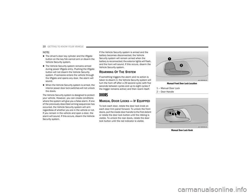
To lock each door, rotate the door lock knob on
each door trim panel forward. To unlock the front
doors, pull the inside door handle to the first detent
or rotate the door lock button until the ribbing is
visible. To unlock the rear doors, rotate the door
lock button until the red indicator is visible.
Manual Front Door Lock Location
Manual Door Lock Knob
1 — Manual Door Lock
2 — Door Handle
21_RUV_OM_EN_USC_t.book Page 20
Page 79 of 348
GETTING TO KNOW YOUR VEHICLE77
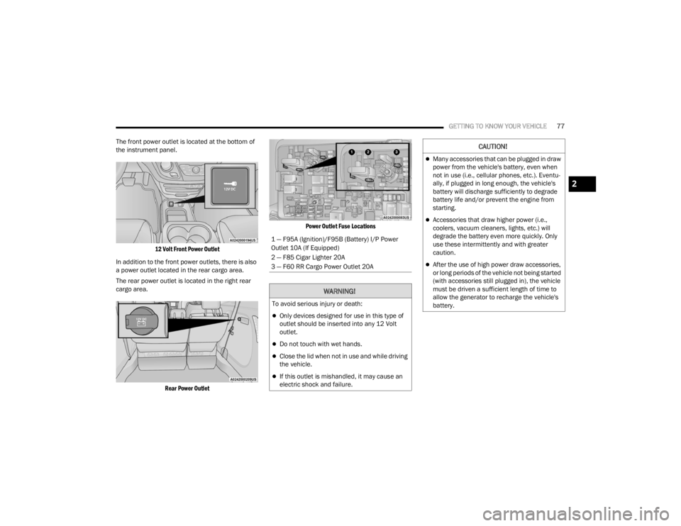
The front power outlet is located at the bottom of
the instrument panel.
12 Volt Front Power Outlet
In addition to the front power outlets, there is also
a power outlet located in the rear cargo area.
The rear power outlet is located in the right rear
cargo area.
Rear Power Outlet Power Outlet Fuse Locations
1 — F95A (Ignition)/F95B (Battery) I/P Power
Outlet 10A (If Equipped)
2 — F85 Cigar Lighter 20A
3 — F60 RR Cargo Power Outlet 20A
WARNING!
To avoid serious injury or death:
Only devices designed for use in this type of
outlet should be inserted into any 12 Volt
outlet.
Do not touch with wet hands.
Close the lid when not in use and while driving
the vehicle.
If this outlet is mishandled, it may cause an
electric shock and failure.
CAUTION!
Many accessories that can be plugged in draw
power from the vehicle's battery, even when
not in use (i.e., cellular phones, etc.). Eventu
-
ally, if plugged in long enough, the vehicle's
battery will discharge sufficiently to degrade
battery life and/or prevent the engine from
starting.
Accessories that draw higher power (i.e.,
coolers, vacuum cleaners, lights, etc.) will
degrade the battery even more quickly. Only
use these intermittently and with greater
caution.
After the use of high power draw accessories,
or long periods of the vehicle not being started
(with accessories still plugged in), the vehicle
must be driven a sufficient length of time to
allow the generator to recharge the vehicle's
battery.
2
21_RUV_OM_EN_USC_t.book Page 77
Page 249 of 348
IN CASE OF EMERGENCY247
(Continued) SOS Call System Limitations
Vehicles sold in Mexico
DO NOT have SOS Call
system capabilities.
SOS or other emergency line operators in Mexico
may not answer or respond to SOS system calls.
If the SOS Call system detects a malfunction, any
of the following may occur at the time the
malfunction is detected, and at the beginning of
each ignition cycle:
The Rearview Mirror light located between the
SOS and ASSIST buttons will continuously illumi -
nate red.
The Device Screen will display the following
message “Vehicle device requires service.
Please contact an authorized dealer.”
An In-Vehicle Audio message will state “Vehicle
device requires service. Please contact an
authorized dealer.”
WARNING!
If anyone in the vehicle could be in danger
(e.g., fire or smoke is visible, dangerous road
conditions or location), do not wait for voice
contact from an Emergency Services Agent. All
occupants should exit the vehicle immediately
and move to a safe location.
Never place anything on or near the vehicle’s
operable network and GPS antennas. You
could prevent operable network and GPS
signal reception, which can prevent your
vehicle from placing an emergency call. An
operable network and GPS signal reception is
required for the SOS Call system to function
properly.
The SOS Call system is embedded into the
vehicle’s electrical system. Do not add after -
market electrical equipment to the vehicle’s
electrical system. This may prevent your
vehicle from sending a signal to initiate an
emergency call. To avoid interference that can
cause the SOS Call system to fail, never add
aftermarket equipment (e.g., two-way mobile
radio, CB radio, data recorder, etc.) to your
vehicle’s electrical system or modify the
antennas on your vehicle. IF YOUR VEHICLE
LOSES BATTERY POWER FOR ANY REASON
(INCLUDING DURING OR AFTER AN ACCI -
DENT), THE UCONNECT FEATURES, APPS AND
SERVICES, AMONG OTHERS, WILL NOT
OPERATE.
Modifications to any part of the SOS Call
system could cause the air bag system to fail
when you need it. You could be injured if the
air bag system is not there to help protect you.
WARNING!
7
21_RUV_OM_EN_USC_t.book Page 247
Page 264 of 348
262IN CASE OF EMERGENCY
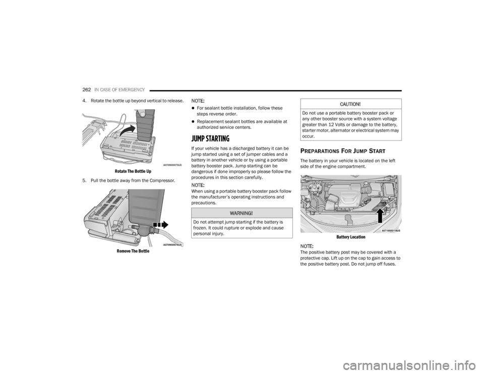
4. Rotate the bottle up beyond vertical to release.
Rotate The Bottle Up
5. Pull the bottle away from the Compressor.
Remove The Bottle
NOTE:
For sealant bottle installation, follow these
steps reverse order.
Replacement sealant bottles are available at
authorized service centers.
JUMP STARTING
If your vehicle has a discharged battery it can be
jump started using a set of jumper cables and a
battery in another vehicle or by using a portable
battery booster pack. Jump starting can be
dangerous if done improperly so please follow the
procedures in this section carefully.
NOTE:When using a portable battery booster pack follow
the manufacturer’s operating instructions and
precautions.
PREPARATIONS FOR JUMP START
The battery in your vehicle is located on the left
side of the engine compartment.
Battery Location
NOTE:The positive battery post may be covered with a
protective cap. Lift up on the cap to gain access to
the positive battery post. Do not jump off fuses.
WARNING!
Do not attempt jump starting if the battery is
frozen. It could rupture or explode and cause
personal injury.
CAUTION!
Do not use a portable battery booster pack or
any other booster source with a system voltage
greater than 12 Volts or damage to the battery,
starter motor, alternator or electrical system may
occur.
21_RUV_OM_EN_USC_t.book Page 262
Page 265 of 348
IN CASE OF EMERGENCY263
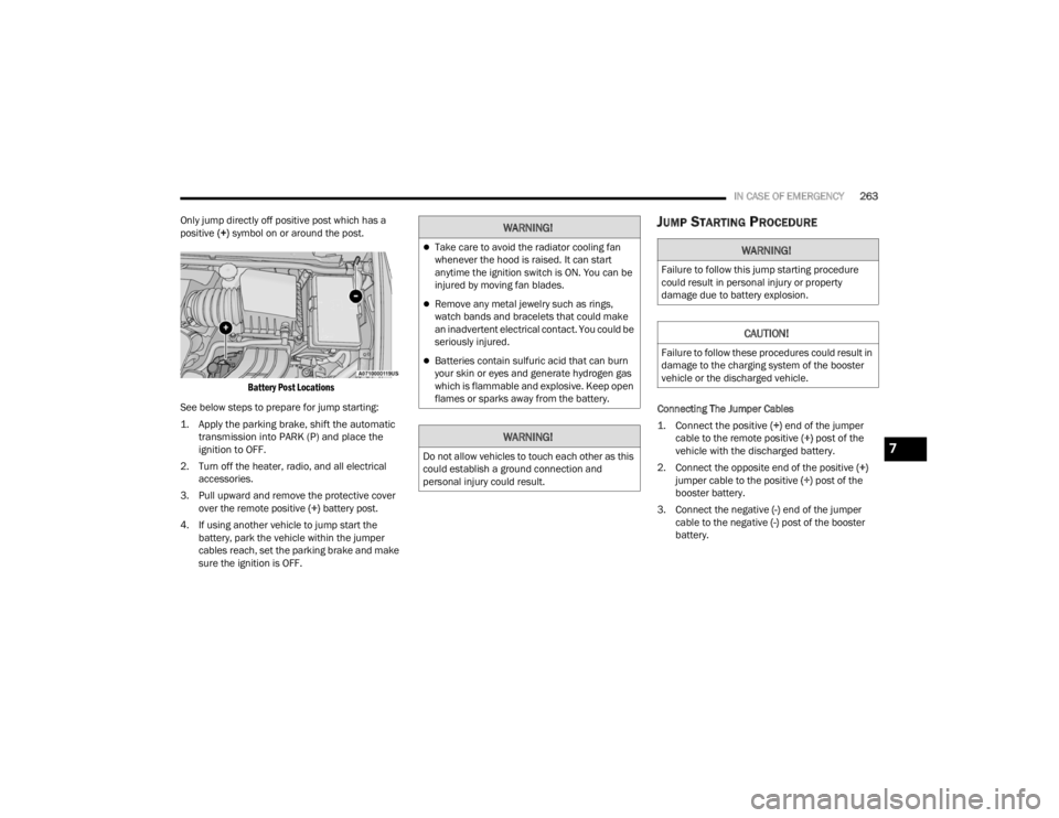
Only jump directly off positive post which has a
positive (+) symbol on or around the post.
Battery Post Locations
See below steps to prepare for jump starting:
1. Apply the parking brake, shift the automatic transmission into PARK (P) and place the
ignition to OFF.
2. Turn off the heater, radio, and all electrical accessories.
3. Pull upward and remove the protective cover over the remote positive (+) battery post.
4. If using another vehicle to jump start the battery, park the vehicle within the jumper
cables reach, set the parking brake and make
sure the ignition is OFF.
JUMP STARTING PROCEDURE
Connecting The Jumper Cables
1. Connect the positive
(+) end of the jumper
cable to the remote positive (+)
post of the
vehicle with the discharged battery.
2. Connect the opposite end of the positive (+)
jumper cable to the positive (+) post of the
booster battery.
3. Connect the negative (-) end of the jumper
cable to the negative (-) post of the booster
battery.
WARNING!
Take care to avoid the radiator cooling fan
whenever the hood is raised. It can start
anytime the ignition switch is ON. You can be
injured by moving fan blades.
Remove any metal jewelry such as rings,
watch bands and bracelets that could make
an inadvertent electrical contact. You could be
seriously injured.
Batteries contain sulfuric acid that can burn
your skin or eyes and generate hydrogen gas
which is flammable and explosive. Keep open
flames or sparks away from the battery.
WARNING!
Do not allow vehicles to touch each other as this
could establish a ground connection and
personal injury could result.
WARNING!
Failure to follow this jump starting procedure
could result in personal injury or property
damage due to battery explosion.
CAUTION!
Failure to follow these procedures could result in
damage to the charging system of the booster
vehicle or the discharged vehicle.
7
21_RUV_OM_EN_USC_t.book Page 263
Page 321 of 348
SERVICING AND MAINTENANCE319
STORING THE VEHICLE
If you are storing your vehicle for more than three
weeks, we recommend that you take the following
steps to minimize the drain on your vehicle's
battery:
Disconnect the negative cable from battery.
Any time you store your vehicle or keep it out of
service (i.e., vacation) for two weeks or more,
run the air conditioning system at idle for about
five minutes in the fresh air and high blower
setting. This will ensure adequate system lubri-
cation to minimize the possibility of compressor
damage when the system is started again.
BODYWORK
PROTECTION FROM ATMOSPHERIC
A
GENTS
Vehicle body care requirements vary according to
geographic locations and usage. Chemicals that
make roads passable in snow and ice and those
that are sprayed on trees and road surfaces during
other seasons are highly corrosive to the metal in
your vehicle. Outside parking, which exposes your
vehicle to airborne contaminants, road surfaces on
which the vehicle is operated, extreme hot or cold
weather and other extreme conditions will have an
adverse effect on paint, metal trim, and underbody
protection. The following maintenance recommendations will
enable you to obtain maximum benefit from the
corrosion resistance built into your vehicle.
What Causes Corrosion?
Corrosion is the result of deterioration or removal
of paint and protective coatings from your vehicle.
The most common causes are:
Road salt, dirt and moisture accumulation
Stone and gravel impact
Insects, tree sap and tar
Salt in the air near seacoast localities
Atmospheric fallout/industrial pollutants
BODY AND UNDERBODY MAINTENANCE
Cleaning Headlights
Your vehicle is equipped with plastic headlights
and fog lights that are lighter and less susceptible
to stone breakage than glass headlights.
Plastic is not as scratch resistant as glass and
therefore different lens cleaning procedures must
be followed.
To minimize the possibility of scratching the lenses
and reducing light output, avoid wiping with a dry
cloth. To remove road dirt, wash with a mild soap
solution followed by rinsing.
Do not use abrasive cleaning components,
solvents, steel wool or other aggressive material to
clean the lenses.
PRESERVING THE BODYWORK
Washing
Wash your vehicle regularly. Always wash your
vehicle in the shade using Mopar® Car Wash, or
a mild car wash soap, and rinse the panels
completely with water.
If insects, tar, or other similar deposits have
accumulated on your vehicle, use Mopar®
Super Kleen Bug and Tar Remover to remove.
Use a high quality cleaner wax, such as Mopar®
Cleaner Wax to remove road film, stains and to
protect your paint finish. Use precautions to not
scratch the paint.
Avoid using abrasive compounds and power
buffing that may diminish the gloss or thin out
the paint finish.
CAUTION!
Do not use abrasive or strong cleaning mate
-
rials such as steel wool or scouring powder
that will scratch metal and painted surfaces.
Use of power washers exceeding 1,200 psi
(8,274 kPa) can result in damage or removal
of paint and decals.
8
21_RUV_OM_EN_USC_t.book Page 319
Page 335 of 348

333
Battery Saver Feature
...................................... 55Belts, Seat..................................................... 242Blind Spot Monitoring.................................... 192Bluetooth Connecting To A Particular MobilePhone Or Audio Device After Pairing
..... 174Body Mechanism Lubrication........................ 282B-Pillar Location............................................. 306Brake Assist System...................................... 187Brake Control System, Electronic.................. 187Brake Fluid.................................................... 327Brake System...................................... 289, 322Anti-Lock (ABS).......................................... 322Fluid Check..................................... 289, 327Master Cylinder......................................... 289Parking...................................................... 111Warning Light.............................................. 97Brake/Transmission Interlock....................... 115Brightness, Interior Lights................................ 56Bulb Replacement............................... 299, 301Bulbs, Light................................. 243, 299, 301
C
Camera.......................................................... 127Camera, Rear................................................ 127Capacities, Fluid............................................ 326Caps, FillerFuel........................................................... 129Oil (Engine)................................................ 275Radiator (Coolant Pressure)...................... 288
Car Washes................................................... 319Carbon Monoxide Warning............................ 244CargoVehicle Loading........................................... 82Cargo Area Cover............................................. 82Cargo CompartmentLuggage Carrier........................................... 83Cargo Load Floor.............................................. 82Cargo Tie-Downs.............................................. 82CD................................................................. 168Cellular Phone.............................................. 185Certification Label......................................... 129Chains, Tire................................................... 316Change Oil Indicator........................................ 90Changing A Flat Tire...................................... 249Chart, Tire Sizing........................................... 303Check Engine Light
(Malfunction Indicator Light)......................... 105Checking Your Vehicle For Safety................. 241Checks, Safety.............................................. 241Child Restraint.............................................. 225Child RestraintsBooster Seats........................................... 228Center Seat LATCH................................... 234Child Seat Installation..................... 236, 238How To Stow An unused ALR Seat Belt.... 235Infant And Child Restraints....................... 226Lower Anchors And Tethers For Children......................................... 229Older Children And Child Restraints......... 227
Seating Positions...................................... 229Using The Top Tether Anchorage.............. 239Cigar Lighter.....................................................78Clean Air Gasoline......................................... 324CleaningWheels...................................................... 315Climate Control................................................58Automatic....................................................58Manual........................................................64Rear......................................................62, 68Coat Hook........................................................74Cold Weather Operation................................ 109Compact Spare Tire...................................... 314Computer, Trip/Travel......................................96Contract, Service........................................... 329Controls........................................................ 160Cooling Pressure Cap (Radiator Cap)............ 288Cooling System............................................. 286Adding Coolant (Antifreeze)...................... 287Coolant Level............................................ 288Cooling Capacity....................................... 326Disposal Of Used Coolant......................... 288Drain, Flush, And Refill............................. 286Inspection........................................ 286, 288Points To Remember................................ 288Pressure Cap............................................ 288Radiator Cap............................................. 288Selection Of Coolant (Antifreeze)..... 287, 326Corrosion Protection..................................... 319Cruise Control............................................... 120
11
21_RUV_OM_EN_USC_t.book Page 333