CHRYSLER VOYAGER 2022 Owners Manual
Manufacturer: CHRYSLER, Model Year: 2022, Model line: VOYAGER, Model: CHRYSLER VOYAGER 2022Pages: 316, PDF Size: 17.41 MB
Page 231 of 316

IN CASE OF EMERGENCY229
Tire Service Kit Storage
The Tire Service Kit is secured with a strap and is
stored in the storage bin located behind the rear
cargo trim panel.
Tire Service Kit Location
Tire Service Kit
Tire Service Kit And Components And Operation
Tire Service Kit Components
Using The Mode Select Knob And Hoses
Your Tire Service Kit is equipped with the following
symbols to indicate the air or sealant mode.
Selecting Air Mode Push in the Mode Select Knob and
turn to this position for air pump oper -
ation only.
Selecting Sealant Mode
Push in the Mode Select Knob and
turn to this position to inject the Tire
Service Kit Sealant and to inflate the
tire.
Using The Power Button
Push and release the Power Button
once to turn On the Tire Service Kit.
Push and release the Power Button
again to turn Off the Tire Service Kit.
Using The Deflation Button Push the Deflation Button to reduce
the air pressure in the tire if it
becomes overinflated.
Tire Service Kit Usage Precautions
Replace the Tire Service Kit Sealant Bottle prior
to the expiration date (printed at the lower right
hand corner on the bottle label) to ensure
optimum operation of the system. See the
Sealant Bottle Replacement in this section for
further information.
1 — Tire Service Kit
2 — Fuel Funnel
1 — Sealant/Air Hose
2 — Hose Accessories
3 — Mode Select Knob
4 — Pressure Gauge
5 — Deflation Button
6 — Power Switch
7 — Sealant Bottle
8 — Power Plug
7
22_RUVG_OM_EN_USC_t.book Page 229
Page 232 of 316
230IN CASE OF EMERGENCY
(Continued)
The Sealant Bottle is a one tire application use
and needs to be replaced after each use. Always
replace these components immediately at your
original equipment vehicle dealer.
When the Tire Service Kit sealant is in a liquid
form, clean water, and a damp cloth will remove
the material from the vehicle or tire and wheel
components. Once the sealant dries, it can
easily be peeled off and properly discarded.
For optimum performance, make sure the valve
stem on the wheel is free of debris before
connecting the Tire Service Kit.
The Tire Service Kit Sealant is only intended to
seal punctures less than 1/4 inch (6 mm) diam-
eter in the tread/contact surface of your
vehicle’s tires.
The Tire Service Kit Sealant is not intended to
seal punctures on the tires' side walls.
You can use the Tire Service Kit air pump to
inflate bicycle tires. The kit also comes with two
needles, located in the Accessory Storage
Compartment (on the bottom of the air pump)
for inflating sport balls, rafts, or similar inflat -
able items. However, use only the Air Pump and
make sure the Mode Select Knob is in the Air
Mode when inflating such items to avoid
injecting sealant into them.
Do not lift or carry the Tire Service Kit by the
hoses.
WARNING!
Do not attempt to seal a tire on the side of the
vehicle closest to traffic. Pull far enough off
the road to avoid the danger of being hit when
using the Tire Service Kit.
Do not use Tire Service Kit or drive the vehicle
under the following circumstances:
If the puncture in the tire tread is approxi -
mately 1/4 inch (6 mm) or larger.
If the tire has any sidewall damage.
If the tire has any damage from driving
with extremely low tire pressure.
If the tire has any damage from driving on
a flat tire.
If the wheel has any damage.
If you are unsure of the condition of the
tire or the wheel.
Keep Tire Service Kit away from open flames
or heat source.
A loose Tire Service Kit thrown forward in a
collision or hard stop could endanger the
occupants of the vehicle. Always stow the Tire
Service Kit in the place provided. Failure to
follow these warnings can result in injuries
that are serious or fatal to you, your passen -
gers, and others around you.
Take care not to allow the contents of Tire
Service Kit to come in contact with hair, eyes,
or clothing. Tire Service Kit sealant is harmful
if inhaled, swallowed, or absorbed through the
skin. It causes skin, eye, and respiratory irrita -
tion. Flush immediately with plenty of water if
there is any contact with eyes or skin. Change
clothing as soon as possible, if there is any
contact with clothing.
Tire Service Kit Sealant solution contains
latex. In case of an allergic reaction or rash,
consult a physician immediately. Keep Tire
Service Kit out of reach of children. If swal -
lowed, rinse mouth immediately with plenty of
water and drink plenty of water. Do not induce
vomiting! Consult a physician immediately.
WARNING!
22_RUVG_OM_EN_USC_t.book Page 230
Page 233 of 316
IN CASE OF EMERGENCY231
Sealing A Tire With Tire Service Kit
Whenever You Stop To Use Tire Service Kit:
1. Pull over to a safe location and turn on the vehicle’s Hazard Warning Flashers.
2. Verify that the valve stem (on the wheel with the deflated tire) is in a position that is near to
the ground. This will allow the Tire Service Kit
Hose to reach the valve stem and keep the Tire
Service Kit flat on the ground. This will provide
the best positioning of the kit when injecting
the sealant into the deflated tire and running
the air pump. Move the vehicle as necessary to
place the valve stem in this position before
proceeding.
3. Place the transmission in PARK (P) and cycle the ignition in the OFF position.
4. Apply the parking brake.
Setting Up To Use Tire Service Kit:
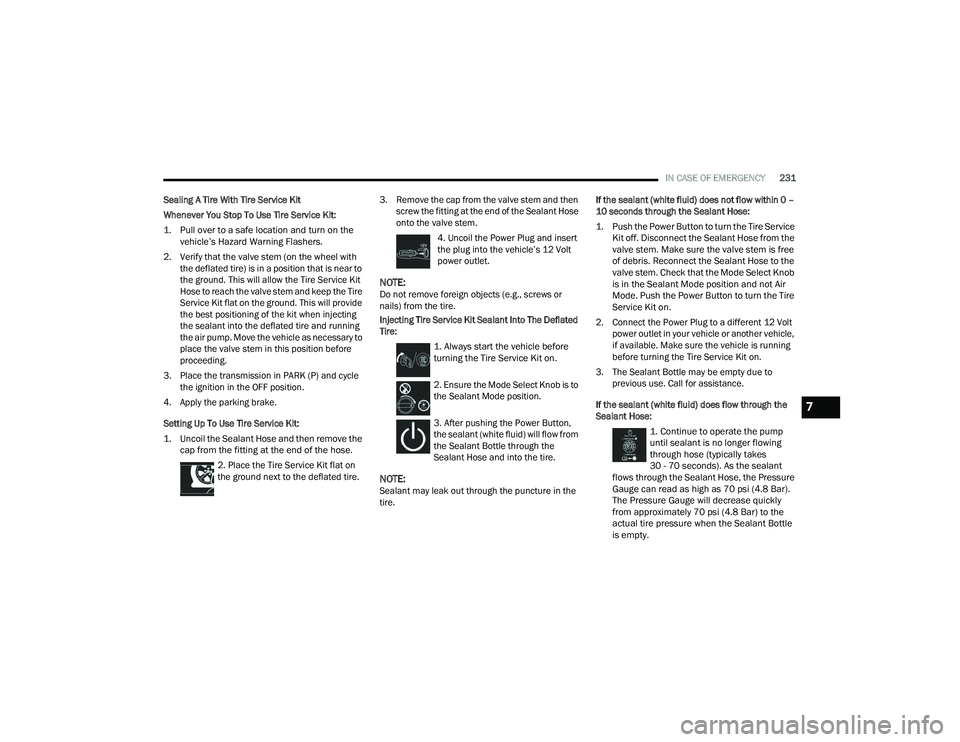
1. Uncoil the Sealant Hose and then remove the cap from the fitting at the end of the hose.
2. Place the Tire Service Kit flat on
the ground next to the deflated tire. 3. Remove the cap from the valve stem and then
screw the fitting at the end of the Sealant Hose
onto the valve stem.
4. Uncoil the Power Plug and insert
the plug into the vehicle’s 12 Volt
power outlet.
NOTE:Do not remove foreign objects (e.g., screws or
nails) from the tire.
Injecting Tire Service Kit Sealant Into The Deflated
Tire:
1. Always start the vehicle before
turning the Tire Service Kit on.
2. Ensure the Mode Select Knob is to
the Sealant Mode position.
3. After pushing the Power Button,
the sealant (white fluid) will flow from
the Sealant Bottle through the
Sealant Hose and into the tire.
NOTE:Sealant may leak out through the puncture in the
tire. If the sealant (white fluid) does not flow within 0 –
10 seconds through the Sealant Hose:
1. Push the Power Button to turn the Tire Service
Kit off. Disconnect the Sealant Hose from the
valve stem. Make sure the valve stem is free
of debris. Reconnect the Sealant Hose to the
valve stem. Check that the Mode Select Knob
is in the Sealant Mode position and not Air
Mode. Push the Power Button to turn the Tire
Service Kit on.
2. Connect the Power Plug to a different 12 Volt power outlet in your vehicle or another vehicle,
if available. Make sure the vehicle is running
before turning the Tire Service Kit on.
3. The Sealant Bottle may be empty due to previous use. Call for assistance.
If the sealant (white fluid) does flow through the
Sealant Hose:
1. Continue to operate the pump
until sealant is no longer flowing
through hose (typically takes
30 - 70 seconds). As the sealant
flows through the Sealant Hose, the Pressure
Gauge can read as high as 70 psi (4.8 Bar).
The Pressure Gauge will decrease quickly
from approximately 70 psi (4.8 Bar) to the
actual tire pressure when the Sealant Bottle
is empty.
7
22_RUVG_OM_EN_USC_t.book Page 231
Page 234 of 316
232IN CASE OF EMERGENCY
2. The pump will start to inject air into
the tire immediately after the
Sealant Bottle is empty. Continue to
operate the pump and inflate the tire
to the cold tire inflation pressure found on the
tire and loading information label located in
the driver-side door opening. Check the tire
pressure by looking at the Pressure Gauge.
If the tire does not inflate to at least 26 psi
(1.8 Bar) pressure within 15 minutes:
The tire is too badly damaged. Do not attempt to
drive the vehicle further. Call for assistance.
If the tire inflates to the recommended pressure or
is at least 26 psi (1.8 Bar) pressure within
15 minutes:
NOTE:If the tire becomes overinflated, push the Deflation
Button to reduce the tire pressure to the recom -
mended inflation pressure before continuing.
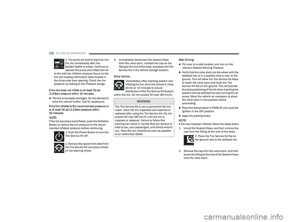
1. Push the Power Button to turn the
Tire Service Kit off.
2. Remove the speed limit label from
the Tire Service Kit and place sticker
on the steering wheel. 3. Immediately disconnect the Sealant Hose
from the valve stem, reinstall the cap on the
fitting at the end of the hose, and place the Tire
Service Kit in the vehicle storage location.
Drive Vehicle: Immediately after injecting sealant and
inflating the tire, drive the vehicle 5 miles
(8 km) or 10 minutes to ensure distribution of the Tire Service Kit Sealant
within the tire. Do not exceed 50 mph (80 km/h). After Driving:
Pull over to a safe location and turn on the
vehicle’s Hazard Warning Flashers.
Verify that the valve stem (on the wheel with the
deflated tire) is in a position that is near to the
ground. This will allow the Tire Service Kit Hose
to reach the valve stem and keep the Tire
Service Kit flat on the ground. This will provide
the best positioning of the kit when injecting the
sealant into the deflated tire and running the air
pump. Move the vehicle as necessary to place
the valve stem in this position before
proceeding.
Place the transmission in PARK (P) and cycle the
ignition in the OFF position.
Apply the parking brake.
NOTE:If tire has improper inflation follow the steps below
1. Uncoil the Sealant Hose, and then remove the
cap from the fitting at the end of the hose.
2. Place the Tire Service Kit flat on
the ground next to the deflated tire.
3. Remove the cap from the valve stem, and then screw the fitting at the end of the Sealant Hose
onto the valve stem.
WARNING!
The Tire Service Kit is not a permanent flat tire
repair. Have the tire inspected and repaired or
replaced after using the Tire Service Kit. Do not
exceed 50 mph (80 km/h) until the tire is
repaired or replaced. Failure to follow this
warning can result in injuries that are serious or
fatal to you, your passengers, and others around
you. Have the tire checked as soon as possible
at an authorized dealer.
22_RUVG_OM_EN_USC_t.book Page 232
Page 235 of 316
IN CASE OF EMERGENCY233
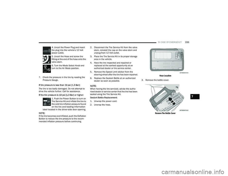
4. Uncoil the Power Plug and insert
the plug into the vehicle's 12 Volt
power outlet.
5. Uncoil the Hose and screw the
fitting at the end of the hose onto the
valve stem.
6. Turn the Mode Select Knob and
turn to the Air Mode position.
7. Check the pressure in the tire by reading the Pressure Gauge.
If tire pressure is less than 19 psi (1.3 Bar):
The tire is too badly damaged. Do not attempt to
drive the vehicle further. Call for assistance.
If the tire pressure is 19 psi (1.3 Bar) or higher:
1. Push the Power Button to turn on
Tire Service Kit and inflate the tire to
the cold tire inflation pressure found
on the tire and loading information
label located in the driver-side door opening.
NOTE:If the tire becomes overinflated, push the Deflation
Button to reduce the tire pressure to the recom -
mended inflation pressure before continuing. 2. Disconnect the Tire Service Kit from the valve
stem, reinstall the cap on the valve stem and
unplug from 12 Volt outlet.
3. Place the Tire Service Kit in its proper storage area in the vehicle.
4. Have the tire inspected and repaired or replaced at the earliest opportunity at an
authorized dealer or tire service center.
5. Remove the Speed Limit sticker from the steering wheel after the tire has been repaired.
6. Replace the Sealant Bottle at an authorized dealer as soon as possible.
NOTE:When having the tire serviced, advise the autho -
rized dealer or service center that the tire has been
sealed using the Tire Service Kit.
Sealant Bottle Replacement:
1. Unwrap the power cord.
2. Unwrap the hose.
Hose Location
3. Remove the bottle cover.
Remove The Bottle Cover
7
22_RUVG_OM_EN_USC_t.book Page 233
Page 236 of 316
234IN CASE OF EMERGENCY
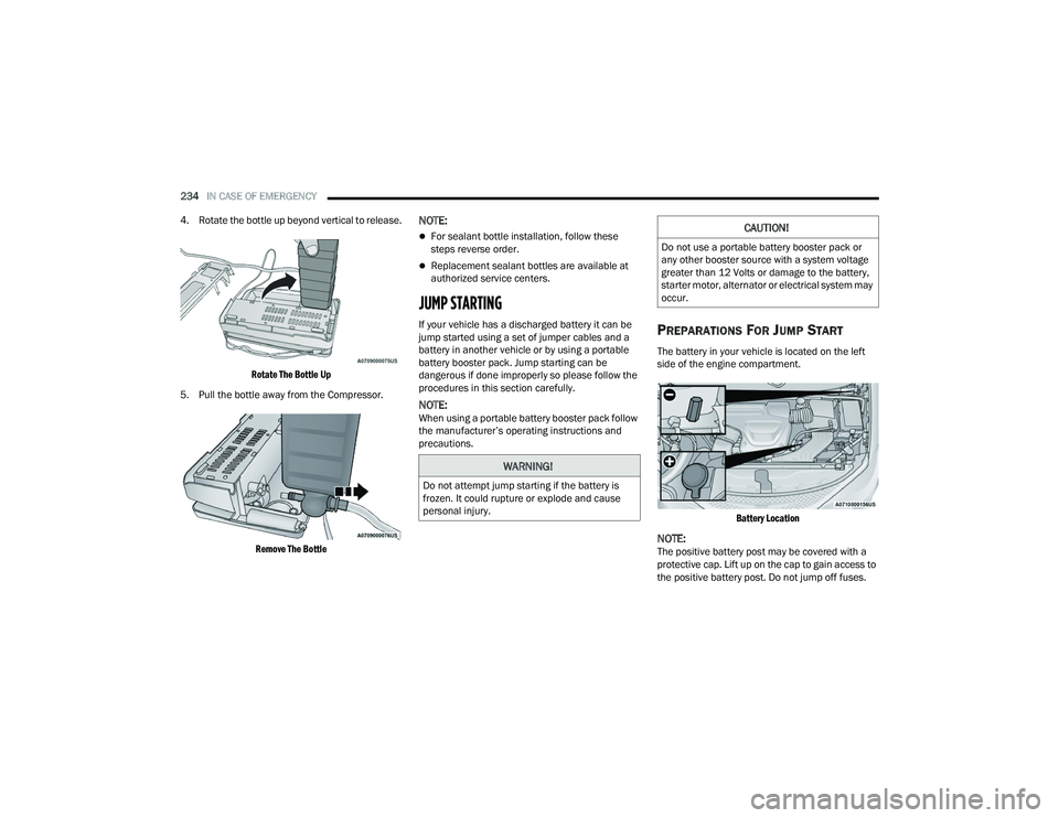
4. Rotate the bottle up beyond vertical to release.
Rotate The Bottle Up
5. Pull the bottle away from the Compressor.
Remove The Bottle
NOTE:
For sealant bottle installation, follow these
steps reverse order.
Replacement sealant bottles are available at
authorized service centers.
JUMP STARTING
If your vehicle has a discharged battery it can be
jump started using a set of jumper cables and a
battery in another vehicle or by using a portable
battery booster pack. Jump starting can be
dangerous if done improperly so please follow the
procedures in this section carefully.
NOTE:When using a portable battery booster pack follow
the manufacturer’s operating instructions and
precautions.
PREPARATIONS FOR JUMP START
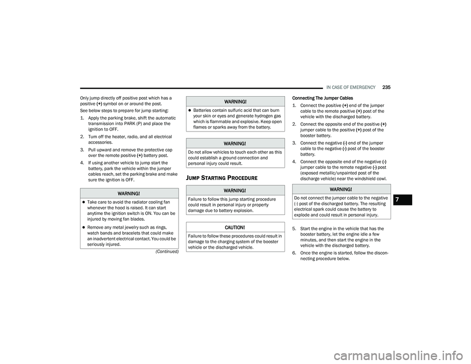
The battery in your vehicle is located on the left
side of the engine compartment.
Battery Location
NOTE:The positive battery post may be covered with a
protective cap. Lift up on the cap to gain access to
the positive battery post. Do not jump off fuses.
WARNING!
Do not attempt jump starting if the battery is
frozen. It could rupture or explode and cause
personal injury.
CAUTION!
Do not use a portable battery booster pack or
any other booster source with a system voltage
greater than 12 Volts or damage to the battery,
starter motor, alternator or electrical system may
occur.
22_RUVG_OM_EN_USC_t.book Page 234
Page 237 of 316
IN CASE OF EMERGENCY235
(Continued)
Only jump directly off positive post which has a
positive
(+) symbol on or around the post.
See below steps to prepare for jump starting:
1. Apply the parking brake, shift the automatic transmission into PARK (P) and place the
ignition to OFF.
2. Turn off the heater, radio, and all electrical accessories.
3. Pull upward and remove the protective cap over the remote positive (+) battery post.
4. If using another vehicle to jump start the battery, park the vehicle within the jumper
cables reach, set the parking brake and make
sure the ignition is OFF.
JUMP STARTING PROCEDURE
Connecting The Jumper Cables
1. Connect the positive
(+) end of the jumper
cable to the remote positive (+)
post of the
vehicle with the discharged battery.
2. Connect the opposite end of the positive (+)
jumper cable to the positive (+) post of the
booster battery.
3. Connect the negative (-) end of the jumper
cable to the negative (-) post of the booster
battery.
4. Connect the opposite end of the negative (-)
jumper cable to the remote negative (-) post
(exposed metallic/unpainted post of the
discharge vehicle) near the windshield cowl.
5. Start the engine in the vehicle that has the booster battery, let the engine idle a few
minutes, and then start the engine in the
vehicle with the discharged battery.
6. Once the engine is started, follow the discon -
necting procedure below.
WARNING!
Take care to avoid the radiator cooling fan
whenever the hood is raised. It can start
anytime the ignition switch is ON. You can be
injured by moving fan blades.
Remove any metal jewelry such as rings,
watch bands and bracelets that could make
an inadvertent electrical contact. You could be
seriously injured.
Batteries contain sulfuric acid that can burn
your skin or eyes and generate hydrogen gas
which is flammable and explosive. Keep open
flames or sparks away from the battery.
WARNING!
Do not allow vehicles to touch each other as this
could establish a ground connection and
personal injury could result.
WARNING!
Failure to follow this jump starting procedure
could result in personal injury or property
damage due to battery explosion.
CAUTION!
Failure to follow these procedures could result in
damage to the charging system of the booster
vehicle or the discharged vehicle.
WARNING!
WARNING!
Do not connect the jumper cable to the negative
(-) post of the discharged battery. The resulting
electrical spark could cause the battery to
explode and could result in personal injury.7
22_RUVG_OM_EN_USC_t.book Page 235
Page 238 of 316
236IN CASE OF EMERGENCY
Disconnecting The Jumper Cables
1. Disconnect the negative
(-)
end of the jumper
cable from the remote negative post of the
vehicle with the discharged battery.
2. Disconnect the opposite end of the negative (-)
jumper cable from the negative (-) post of the
booster battery.
3. Disconnect the positive (+) end of the jumper
cable from the positive (+) post of the booster
battery.
4. Disconnect the opposite end of the positive (+)
jumper cable from the remote positive (+) post
of the vehicle with the discharged battery and
reinstall the protective cap.
If frequent jump starting is required to start your
vehicle you should have the battery and charging
system inspected at an authorized dealer.
REFUELING IN EMERGENCY – IF EQUIPPED
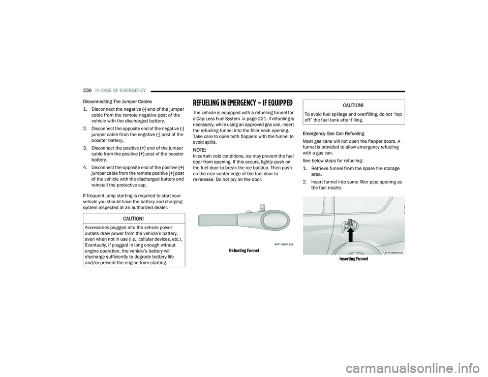
The vehicle is equipped with a refueling funnel for
a Cap-Less Fuel System Úpage 221. If refueling is
necessary, while using an approved gas can, insert
the refueling funnel into the filler neck opening.
Take care to open both flappers with the funnel to
avoid spills.
NOTE:In certain cold conditions, ice may prevent the fuel
door from opening. If this occurs, lightly push on
the fuel door to break the ice buildup. Then push
on the rear center edge of the fuel door to
re-release. Do not pry on the door.
Refueling Funnel
Emergency Gas Can Refueling
Most gas cans will not open the flapper doors. A
funnel is provided to allow emergency refueling
with a gas can.
See below steps for refueling:
1. Retrieve funnel from the spare tire storage
area.
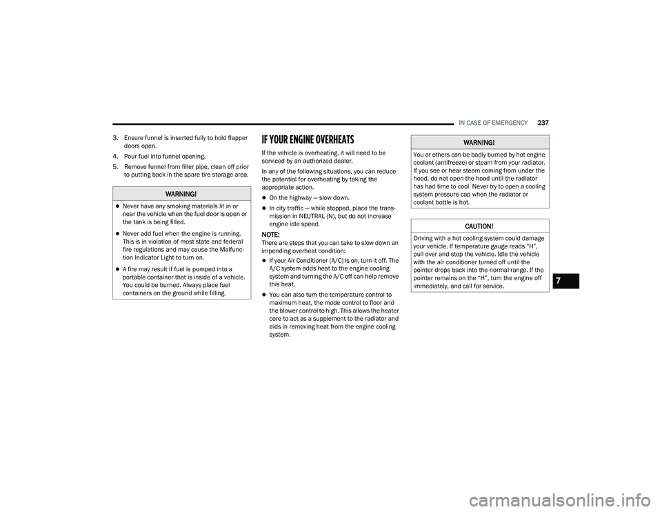
2. Insert funnel into same filler pipe opening as the fuel nozzle.
Inserting Funnel
CAUTION!
Accessories plugged into the vehicle power
outlets draw power from the vehicle’s battery,
even when not in use (i.e., cellular devices, etc.).
Eventually, if plugged in long enough without
engine operation, the vehicle’s battery will
discharge sufficiently to degrade battery life
and/or prevent the engine from starting.
CAUTION!
To avoid fuel spillage and overfilling, do not “top
off” the fuel tank after filling.
22_RUVG_OM_EN_USC_t.book Page 236
Page 239 of 316
IN CASE OF EMERGENCY237
3. Ensure funnel is inserted fully to hold flapper doors open.
4. Pour fuel into funnel opening.
5. Remove funnel from filler pipe, clean off prior to putting back in the spare tire storage area.
IF YOUR ENGINE OVERHEATS
If the vehicle is overheating, it will need to be
serviced by an authorized dealer.
In any of the following situations, you can reduce
the potential for overheating by taking the
appropriate action.
On the highway — slow down.
In city traffic — while stopped, place the trans -
mission in NEUTRAL (N), but do not increase
engine idle speed.
NOTE:There are steps that you can take to slow down an
impending overheat condition:
If your Air Conditioner (A/C) is on, turn it off. The
A/C system adds heat to the engine cooling
system and turning the A/C off can help remove
this heat.
You can also turn the temperature control to
maximum heat, the mode control to floor and
the blower control to high. This allows the heater
core to act as a supplement to the radiator and
aids in removing heat from the engine cooling
system.
WARNING!
Never have any smoking materials lit in or
near the vehicle when the fuel door is open or
the tank is being filled.
Never add fuel when the engine is running.
This is in violation of most state and federal
fire regulations and may cause the Malfunc -
tion Indicator Light to turn on.
A fire may result if fuel is pumped into a
portable container that is inside of a vehicle.
You could be burned. Always place fuel
containers on the ground while filling.
WARNING!
You or others can be badly burned by hot engine
coolant (antifreeze) or steam from your radiator.
If you see or hear steam coming from under the
hood, do not open the hood until the radiator
has had time to cool. Never try to open a cooling
system pressure cap when the radiator or
coolant bottle is hot.
CAUTION!
Driving with a hot cooling system could damage
your vehicle. If temperature gauge reads “H”,
pull over and stop the vehicle. Idle the vehicle
with the air conditioner turned off until the
pointer drops back into the normal range. If the
pointer remains on the “H”, turn the engine off
immediately, and call for service.
7
22_RUVG_OM_EN_USC_t.book Page 237
Page 240 of 316
238IN CASE OF EMERGENCY
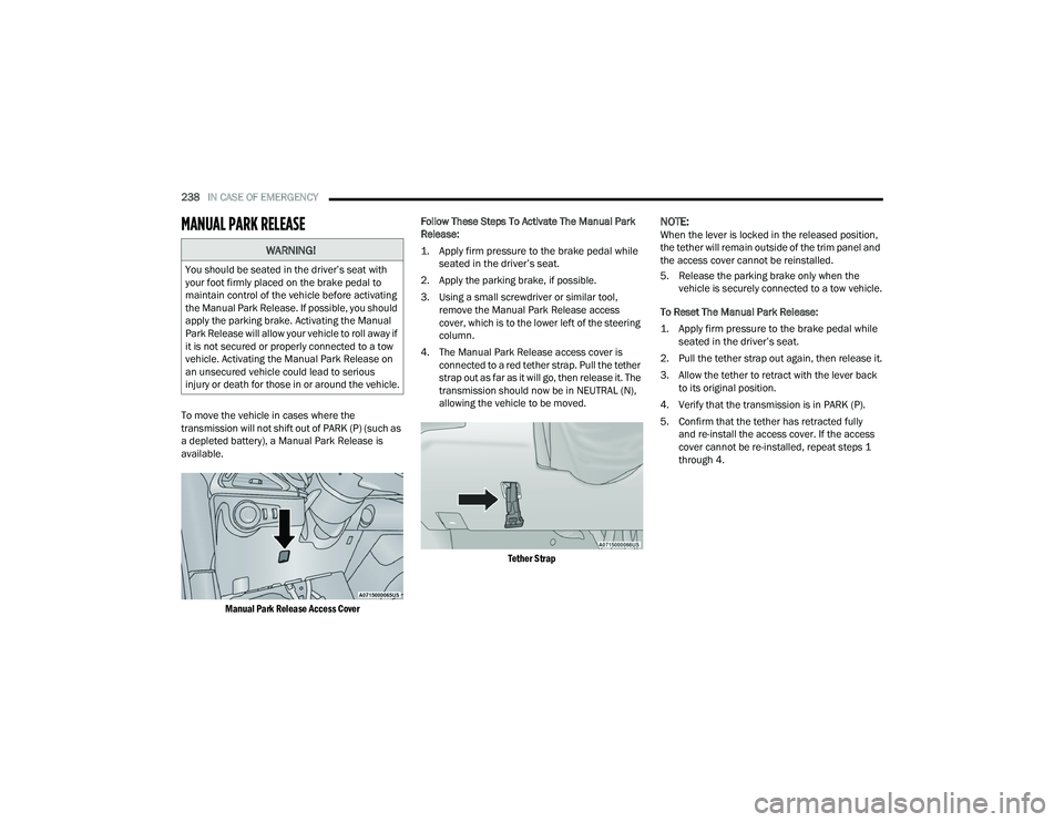
MANUAL PARK RELEASE
To move the vehicle in cases where the
transmission will not shift out of PARK (P) (such as
a depleted battery), a Manual Park Release is
available.
Manual Park Release Access Cover
Follow These Steps To Activate The Manual Park
Release:
1. Apply firm pressure to the brake pedal while
seated in the driver’s seat.
2. Apply the parking brake, if possible.
3. Using a small screwdriver or similar tool, remove the Manual Park Release access
cover, which is to the lower left of the steering
column.
4. The Manual Park Release access cover is connected to a red tether strap. Pull the tether
strap out as far as it will go, then release it. The
transmission should now be in NEUTRAL (N),
allowing the vehicle to be moved.
Tether Strap
NOTE:When the lever is locked in the released position,
the tether will remain outside of the trim panel and
the access cover cannot be reinstalled.
5. Release the parking brake only when the vehicle is securely connected to a tow vehicle.
To Reset The Manual Park Release:
1. Apply firm pressure to the brake pedal while seated in the driver’s seat.
2. Pull the tether strap out again, then release it.
3. Allow the tether to retract with the lever back to its original position.
4. Verify that the transmission is in PARK (P).
5. Confirm that the tether has retracted fully and re-install the access cover. If the access
cover cannot be re-installed, repeat steps 1
through 4.
WARNING!
You should be seated in the driver’s seat with
your foot firmly placed on the brake pedal to
maintain control of the vehicle before activating
the Manual Park Release. If possible, you should
apply the parking brake. Activating the Manual
Park Release will allow your vehicle to roll away if
it is not secured or properly connected to a tow
vehicle. Activating the Manual Park Release on
an unsecured vehicle could lead to serious
injury or death for those in or around the vehicle.
22_RUVG_OM_EN_USC_t.book Page 238