CHRYSLER VOYAGER 2022 Owners Manual
Manufacturer: CHRYSLER, Model Year: 2022, Model line: VOYAGER, Model: CHRYSLER VOYAGER 2022Pages: 316, PDF Size: 17.41 MB
Page 271 of 316
SERVICING AND MAINTENANCE269
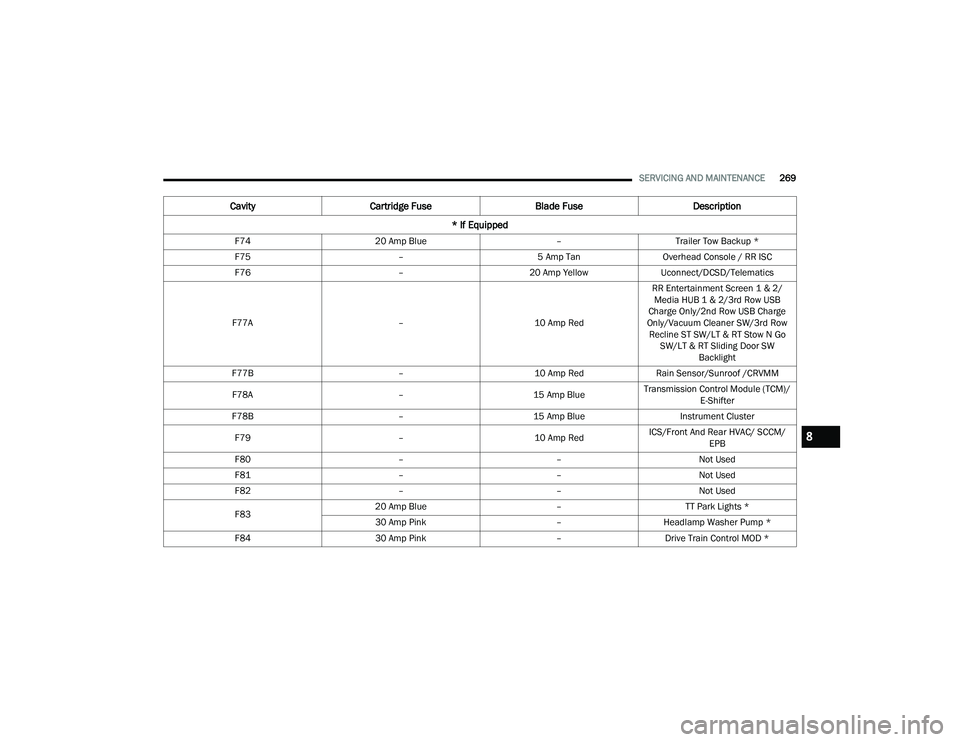
F74 20 Amp Blue –Trailer Tow Backup *
F75 –5 Amp TanOverhead Console / RR ISC
F76 –20 Amp YellowUconnect/DCSD/Telematics
F77A –10 Amp RedRR Entertainment Screen 1 & 2/
Media HUB 1 & 2/3rd Row USB
Charge Only/2nd Row USB Charge
Only/Vacuum Cleaner SW/3rd Row Recline ST SW/LT & RT Stow N Go SW/LT & RT Sliding Door SW Backlight
F77B –10 Amp RedRain Sensor/Sunroof /CRVMM
F78A –15 Amp BlueTransmission Control Module (TCM)/
E-Shifter
F78B –15 Amp Blue Instrument Cluster
F79 –10 Amp RedICS/Front And Rear HVAC/ SCCM/
EPB
F80 ––Not Used
F81 ––Not Used
F82 ––Not Used
F83 20 Amp Blue
–TT Park Lights *
30 Amp Pink –Headlamp Washer Pump *
F84 30 Amp Pink –Drive Train Control MOD *
Cavity Cartridge Fuse Blade FuseDescription
* If Equipped
8
22_RUVG_OM_EN_USC_t.book Page 269
Page 272 of 316
270SERVICING AND MAINTENANCE
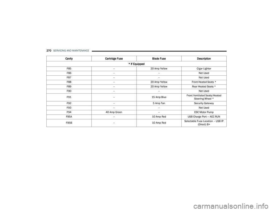
F85 –20 Amp Yellow Cigar Lighter
F86 ––Not Used
F87 ––Not Used
F88 –20 Amp Yellow Front Heated Seats *
F89 –20 Amp Yellow Rear Heated Seats *
F90 ––Not Used
F91 –15 Amp BlueFront Ventilated Seats/Heated
Steering Wheel *
F92 –5 Amp Tan Security Gateway
F93 ––Not Used
F94 40 Amp Green –ESC Motor Pump
F95A –10 Amp RedUSB Charge Port — ACC RUN
F95B –10 Amp RedSelectable Fuse Location – USB IP
(Direct) B+
Cavity Cartridge Fuse Blade FuseDescription
* If Equipped
22_RUVG_OM_EN_USC_t.book Page 270
Page 273 of 316
SERVICING AND MAINTENANCE271
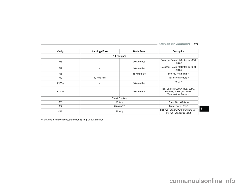
** 30 Amp mini fuse is substituted for 25 Amp Circuit Breaker. F96
–10 Amp RedOccupant Restraint Controller (ORC)
(Airbag)
F97 –10 Amp RedOccupant Restraint Controller (ORC)
(Airbag)
F98 –15 Amp Blue Left HID Headlamp *
F99 30 Amp Pink –Trailer Tow Module *
F100A –10 Amp Red AHLM *
F100B –10 Amp RedRear Camera/LBSS/RBSS/CVPM/
Humidity Sensor/In Vehicle Temperature Sensor *
Circuit Breakers
CB1 25 AmpPower Seats (Driver)
CB2 25 Amp **Power Seats (Pass)
CB3 25 AmpFRT PWR Window W/O Door Nodes +
RR PWR Window Lockout
Cavity Cartridge Fuse Blade FuseDescription
* If Equipped
8
22_RUVG_OM_EN_USC_t.book Page 271
Page 274 of 316
272SERVICING AND MAINTENANCE
BULB REPLACEMENT
Replacement Bulbs, Names, And Part Numbers
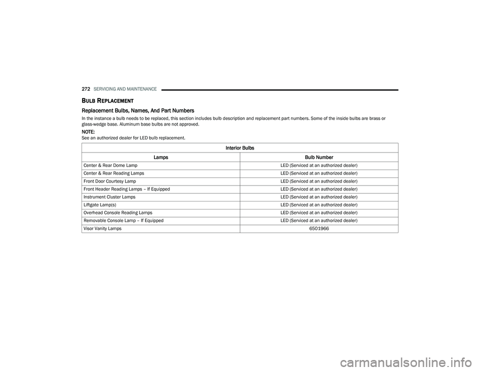
In the instance a bulb needs to be replaced, this section includes bulb description and replacement part numbers. Some of the inside bulbs are brass or
glass-wedge base. Aluminum base bulbs are not approved.
NOTE:See an authorized dealer for LED bulb replacement.
Interior Bulbs
Lamps Bulb Number
Center & Rear Dome Lamp LED (Serviced at an authorized dealer)
Center & Rear Reading Lamps LED (Serviced at an authorized dealer)
Front Door Courtesy Lamp LED (Serviced at an authorized dealer)
Front Header Reading Lamps – If Equipped LED (Serviced at an authorized dealer)
Instrument Cluster Lamps LED (Serviced at an authorized dealer)
Liftgate Lamp(s) LED (Serviced at an authorized dealer)
Overhead Console Reading Lamps LED (Serviced at an authorized dealer)
Removable Console Lamp – If Equipped LED (Serviced at an authorized dealer)
Visor Vanity Lamps 6501966
22_RUVG_OM_EN_USC_t.book Page 272
Page 275 of 316
SERVICING AND MAINTENANCE273
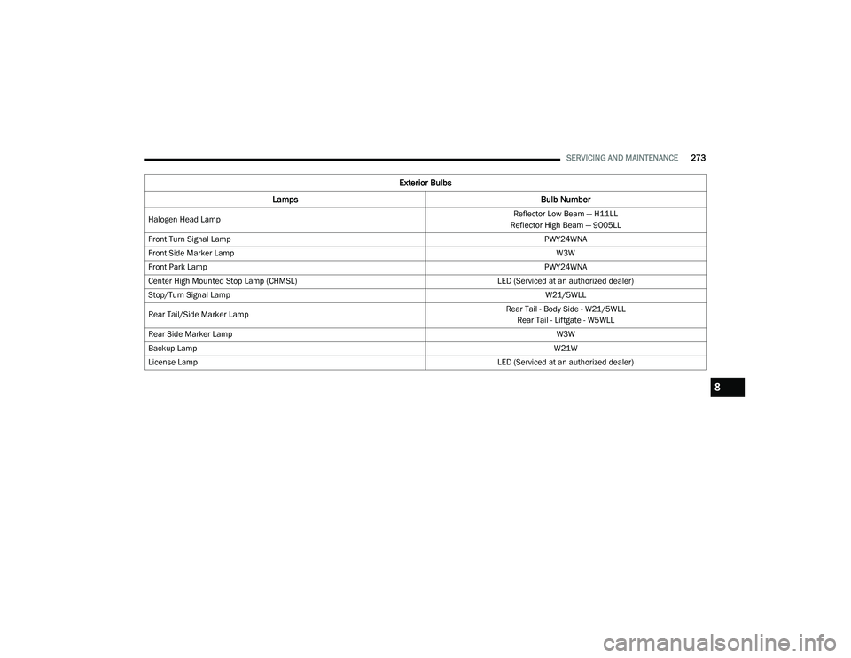
Exterior Bulbs
Lamps Bulb Number
Halogen Head Lamp Reflector Low Beam — H11LL
Reflector High Beam — 9005LL
Front Turn Signal Lamp PWY24WNA
Front Side Marker Lamp W3W
Front Park Lamp PWY24WNA
Center High Mounted Stop Lamp (CHMSL) LED (Serviced at an authorized dealer)
Stop/Turn Signal Lamp W21/5WLL
Rear Tail/Side Marker Lamp Rear Tail - Body Side - W21/5WLL
Rear Tail - Liftgate - W5WLL
Rear Side Marker Lamp W3W
Backup Lamp W21W
License Lamp LED (Serviced at an authorized dealer)
8
22_RUVG_OM_EN_USC_t.book Page 273
Page 276 of 316
274SERVICING AND MAINTENANCE
Replacing Exterior Bulbs
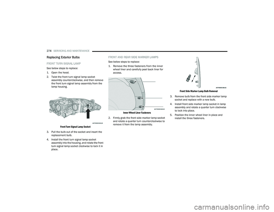
FRONT TURN SIGNAL LAMP
See below steps to replace:
1. Open the hood.
2. Twist the front turn signal lamp socket
assembly counterclockwise, and then remove
the front turn signal lamp assembly from the
lamp housing.
Front Turn Signal Lamp Socket
3. Pull the bulb out of the socket and insert the replacement bulb.
4. Install the front turn signal lamp socket assembly into the housing, and rotate the front
turn signal lamp socket clockwise to lock it in
place.
FRONT AND REAR SIDE MARKER LAMPS
See below steps to replace:
1. Remove the three fasteners from the inner wheel liner and carefully peel back liner for
access.
Inner Wheel Liner Fasteners
2. Firmly grab the front side marker lamp socket and rotate a quarter turn counterclockwise to
remove it from the lamp assembly.
Front Side Marker Lamp Bulb Removal
3. Remove bulb from the front side marker lamp socket and replace with a new bulb.
4. Install front side marker lamp socket in lamp assembly and rotate a quarter turn clockwise
to lock into place.
5. Position the inner wheel liner in place and install the three fasteners.
22_RUVG_OM_EN_USC_t.book Page 274
Page 277 of 316
SERVICING AND MAINTENANCE275
TIRES
TIRE SAFETY INFORMATION
Tire safety information will cover aspects of the
following information: Tire Markings, Tire
Identification Numbers, Tire Terminology and
Definitions, Tire Pressures, and Tire Loading.
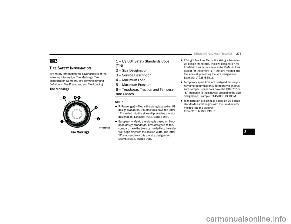
Tire Markings
Tire Markings
NOTE:
P (Passenger) — Metric tire sizing is based on US
design standards. P-Metric tires have the letter
“P” molded into the sidewall preceding the size
designation. Example: P215/65R15 95H.
European — Metric tire sizing is based on Euro -
pean design standards. Tires designed to this
standard have the tire size molded into the side -
wall beginning with the section width. The letter
"P" is absent from this tire size designation.
Example: 215/65R15 96H.
LT (Light Truck) — Metric tire sizing is based on
US design standards. The size designation for
LT-Metric tires is the same as for P-Metric tires
except for the letters “LT” that are molded into
the sidewall preceding the size designation.
Example: LT235/85R16.
Temporary spare tires are designed for tempo -
rary emergency use only. Temporary high pres -
sure compact spare tires have the letter “T” or
“S” molded into the sidewall preceding the size
designation. Example: T145/80D18 103M.
High flotation tire sizing is based on US design
standards and it begins with the tire diameter
molded into the sidewall.
Example: 31x10.5 R15 LT.
1 — US DOT Safety Standards Code
(TIN)
2 — Size Designation
3 — Service Description
4 — Maximum Load
5 — Maximum Pressure
6 — Treadwear, Traction and Tempera -
ture Grades
8
22_RUVG_OM_EN_USC_t.book Page 275
Page 278 of 316
276SERVICING AND MAINTENANCE
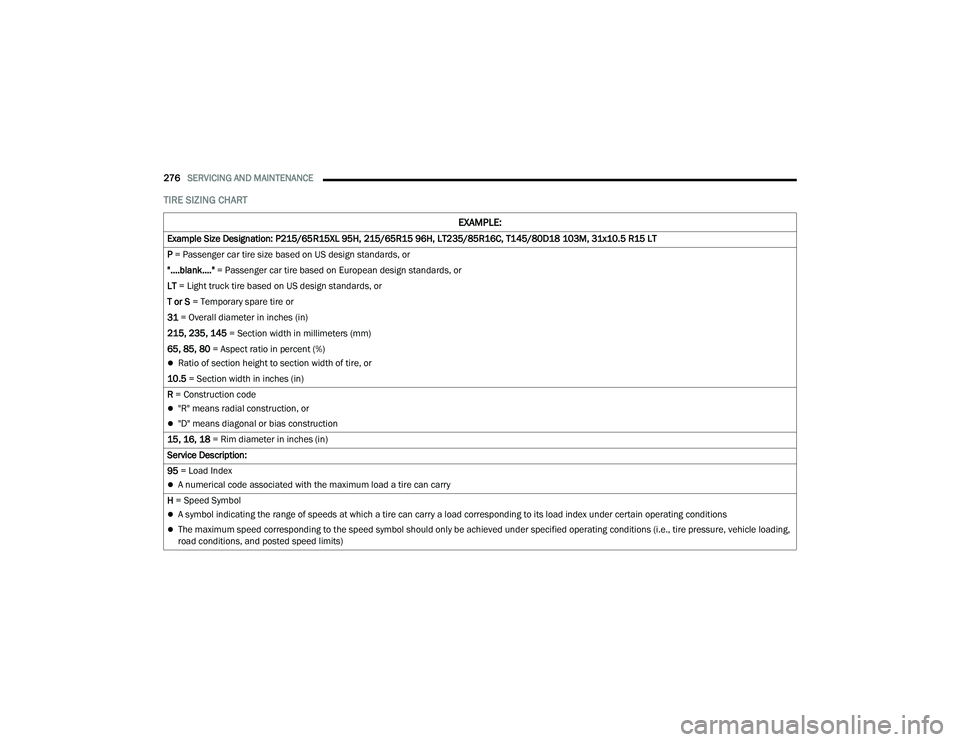
TIRE SIZING CHART
EXAMPLE:
Example Size Designation: P215/65R15XL 95H, 215/65R15 96H, LT235/85R16C, T145/80D18 103M, 31x10.5 R15 LT
P = Passenger car tire size based on US design standards, or
"....blank...." = Passenger car tire based on European design standards, or
LT = Light truck tire based on US design standards, or
T or S = Temporary spare tire or
31 = Overall diameter in inches (in)
215, 235, 145 = Section width in millimeters (mm)
65, 85, 80 = Aspect ratio in percent (%)
Ratio of section height to section width of tire, or
10.5 = Section width in inches (in)
R = Construction code
"R" means radial construction, or
"D" means diagonal or bias construction
15, 16, 18 = Rim diameter in inches (in)
Service Description:
95 = Load Index
A numerical code associated with the maximum load a tire can carry
H = Speed Symbol
A symbol indicating the range of speeds at which a tire can carry a load corresponding to its load index under certain operating conditions
The maximum speed corresponding to the speed symbol should only be achieved under specified operating conditions (i.e., tire pressure, vehicle loading,
road conditions, and posted speed limits)
22_RUVG_OM_EN_USC_t.book Page 276
Page 279 of 316
SERVICING AND MAINTENANCE277
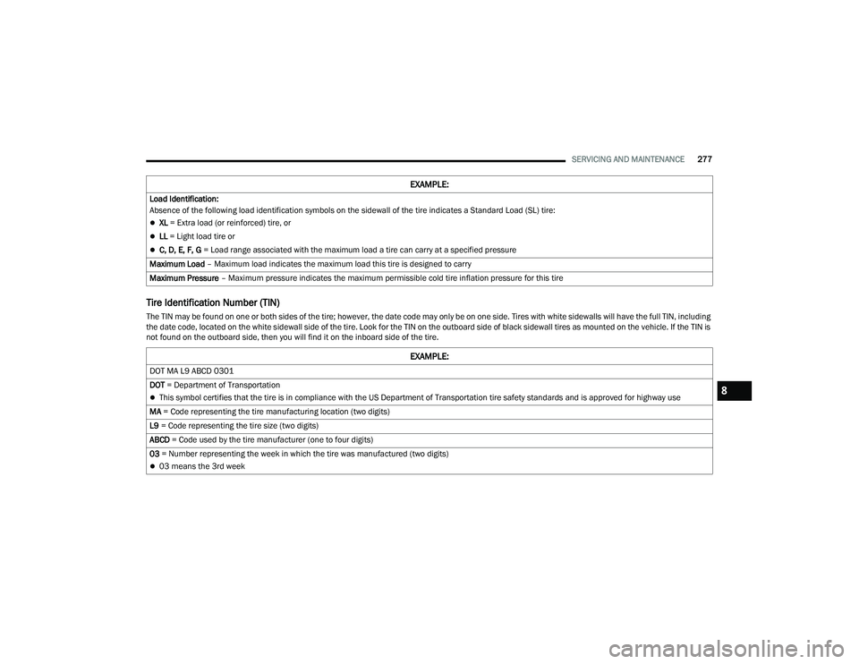
Tire Identification Number (TIN)
The TIN may be found on one or both sides of the tire; however, the date code may only be on one side. Tires with white sidewalls will have the full TIN, including
the date code, located on the white sidewall side of the tire. Look for the TIN on the outboard side of black sidewall tires as mounted on the vehicle. If the TIN is
not found on the outboard side, then you will find it on the inboard side of the tire.Load Identification:
Absence of the following load identification symbols on the sidewall of the tire indicates a Standard Load (SL) tire:
XL = Extra load (or reinforced) tire, or
LL
= Light load tire or
C, D, E, F, G = Load range associated with the maximum load a tire can carry at a specified pressure
Maximum Load – Maximum load indicates the maximum load this tire is designed to carry
Maximum Pressure – Maximum pressure indicates the maximum permissible cold tire inflation pressure for this tire
EXAMPLE:
EXAMPLE:
DOT MA L9 ABCD 0301
DOT = Department of Transportation
This symbol certifies that the tire is in compliance with the US Department of Transportation tire safety standards and is approved for highway use
MA = Code representing the tire manufacturing location (two digits)
L9 = Code representing the tire size (two digits)
ABCD = Code used by the tire manufacturer (one to four digits)
03 = Number representing the week in which the tire was manufactured (two digits)
03 means the 3rd week
8
22_RUVG_OM_EN_USC_t.book Page 277
Page 280 of 316
278SERVICING AND MAINTENANCE
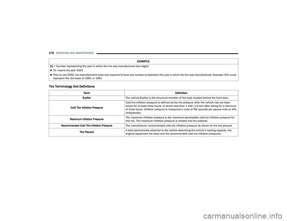
Tire Terminology And Definitions
01 = Number representing the year in which the tire was manufactured (two digits)
01 means the year 2001
Prior to July 2000, tire manufacturers were only required to have one number to represent the year in which the tire was manufactured. Example: 031 could
represent the 3rd week of 1981 or 1991
Term Definition
B-pillarThe vehicle B-pillar is the structural member of the body located behind the front door.
Cold Tire Inflation Pressure Cold tire inflation pressure is defined as the tire pressure after the vehicle has not been
driven for at least three hours, or driven less than 1 mile (1.6 km) after sitting for a minimum
of three hours. Inflation pressure is measured in units of PSI (pounds per square inch) or kPa
(kilopascals).
Maximum Inflation Pressure The maximum inflation pressure is the maximum permissible cold tire inflation pressure for
this tire. The maximum inflation pressure is molded into the sidewall.
Recommended Cold Tire Inflation Pressure The manufacturer recommended cold tire inflation pressure as shown on the tire placard.
Tire Placard A label permanently attached to the vehicle describing the vehicle’s loading capacity, the
original equipment tire sizes and the recommended cold tire inflation pressures.
EXAMPLE:
22_RUVG_OM_EN_USC_t.book Page 278