Control panel CHRYSLER VOYAGER 2022 Owner's Manual
[x] Cancel search | Manufacturer: CHRYSLER, Model Year: 2022, Model line: VOYAGER, Model: CHRYSLER VOYAGER 2022Pages: 316, PDF Size: 17.41 MB
Page 100 of 316
98GETTING TO KNOW YOUR INSTRUMENT PANEL
Vehicle Security Warning Light —
If Equipped
This warning light will flash at a fast rate
for approximately 15 seconds when the
vehicle security system is arming, and
then will flash slowly until the vehicle is
disarmed.
YELLOW WARNING LIGHTS
Anti-Lock Brake System (ABS) Warning
Light
This warning light monitors the ABS. The
light will turn on when the ignition is
placed in the ON/RUN or ACC/ON/RUN
position and may stay on for as long as
four seconds. If the ABS light remains on or turns on while
driving, then the Anti-Lock portion of the brake
system is not functioning and service is required as
soon as possible. However, the conventional brake
system will continue to operate normally,
assuming the Brake Warning Light is not also on.
If the ABS light does not turn on when the ignition
is placed in the ON/RUN or ACC/ON/RUN position,
have the brake system inspected by an authorized
dealer.
Electronic Park Brake Warning Light
This warning light will illuminate to
indicate the Electronic Park Brake is not
functioning properly and service is
required. Contact an authorized dealer.
Electronic Stability Control (ESC) Active
Warning Light — If Equipped
This warning light will indicate when the
ESC system is Active. The ESC Indicator
Light in the instrument cluster will come
on when the ignition is placed in the ON/
RUN or ACC/ON/RUN position, and when ESC is
activated. It should go out with the engine running.
If the ESC Indicator Light comes on continuously
with the engine running, a malfunction has been detected in the ESC system. If this warning light
remains on after several ignition cycles, and the
vehicle has been driven several miles (kilometers)
at speeds greater than 30 mph (48 km/h), see an
authorized dealer as soon as possible to have the
problem diagnosed and corrected.
The ESC OFF Indicator Light and the ESC Indi
-
cator Light come on momentarily each time the
ignition is placed in the ON/RUN or ACC/ON/
RUN position.
The ESC system will make buzzing or clicking
sounds when it is active. This is normal; the
sounds will stop when ESC becomes inactive.
This light will come on when the vehicle is in an
ESC event.
Electronic Stability Control (ESC) OFF
Warning Light — If Equipped
This warning light indicates the ESC is off.
Each time the ignition is turned to
ON/RUN or ACC/ON/RUN, the ESC
system will be on, even if it was turned off
previously.
CAUTION!
Continuous driving with the Transmission
Temperature Warning Light illuminated will
eventually cause severe transmission damage
or transmission failure.
22_RUVG_OM_EN_USC_t.book Page 98
Page 101 of 316
GETTING TO KNOW YOUR INSTRUMENT PANEL99
Engine Check/Malfunction Indicator
Warning Light
The Engine Check/Malfunction Indicator
Light (MIL) is a part of an Onboard
Diagnostic System called OBD II that
monitors engine and automatic
transmission control systems. This warning light
will illuminate when the ignition is in the ON/RUN
position before engine start. If the bulb does not
come on when turning the ignition switch from OFF
to ON/RUN, have the condition checked promptly.
Certain conditions, such as a loose or missing gas
cap, poor quality fuel, etc., may illuminate the light
after engine start. The vehicle should be serviced if
the light stays on through several typical driving
styles. In most situations, the vehicle will drive
normally and will not require towing.
When the engine is running, the MIL may flash to
alert serious conditions that could lead to
immediate loss of power or severe catalytic
converter damage. The vehicle should be serviced
by an authorized dealer as soon as possible if this
occurs.
Low Fuel Warning Light
When the fuel level reaches
approximately 1.85 gal (7 L) this warning
light will turn on, and remain on until fuel
is added.
A single warning chime will sound with Low Fuel
Warning.
Low Washer Fluid Warning Light —
If Equipped
This warning light will illuminate when the
windshield washer fluid is low.
Service Automatic Emergency Braking
(AEB) Warning Light — If Equipped
This warning light will illuminate to
indicate a fault in the AEB Warning
System. Contact an authorized dealer for
service
Úpage 168.
Service Stop/Start System Warning Light —
If Equipped
This warning light will illuminate when the
Stop/Start system is not functioning
properly and service is required. Contact
an authorized dealer for service
Úpage 117.
WARNING!
A malfunctioning catalytic converter, as
referenced above, can reach higher
temperatures than in normal operating
conditions. This can cause a fire if you drive
slowly or park over flammable substances such
as dry plants, wood, cardboard, etc. This could
result in death or serious injury to the driver,
occupants or others.
CAUTION!
Prolonged driving with the Malfunction Indicator
Light (MIL) on could cause damage to the
vehicle control system. It also could affect fuel
economy and driveability. If the MIL is flashing,
severe catalytic converter damage and power
loss will soon occur. Immediate service is
required.
3
22_RUVG_OM_EN_USC_t.book Page 99
Page 103 of 316
GETTING TO KNOW YOUR INSTRUMENT PANEL101
YELLOW INDICATOR LIGHTS
Automatic Emergency Braking (AEB) OFF
Indicator Light — If Equipped
This indicator light illuminates to indicate
that Forward Collision Warning is off.
GREEN INDICATOR LIGHTS
Cruise Control Set Indicator Light —
If Equipped
This indicator light will illuminate when
the cruise control is set to the desired
speed
Úpage 119.
Front Fog Indicator Light — If Equipped
This indicator light will illuminate when
the front fog lights are on.
KeySense Indicator Light — If Equipped
The KeySense indicator is illuminated
when a KeySense key is detected upon
startup of the vehicle. The indicator will
remain lit for the entire key cycle as a
reminder that the KeySense key is in use. While
the KeySense key is in use, the vehicle will respond
to settings associated with the KeySense profile
Úpage 12.
Parking/Headlight On Indicator Light
This indicator light will illuminate when
the park lights or headlights are turned
on.
Stop/Start Active Indicator Light —
If Equipped
This indicator light will illuminate when
the Stop/Start function is in “Autostop”
mode
Úpage 117.
Turn Signal Indicator Lights
When the left or right turn signal is
activated, the turn signal indicator will
flash independently and the
corresponding exterior turn signal lamps
will flash. Turn signals can be activated when the
multifunction lever is moved down (left) or up
(right).
NOTE:
A continuous chime will sound if the vehicle is
driven more than 1 mile (1.6 km) with either
turn signal on.
Check for an inoperative outside light bulb if
either indicator flashes at a rapid rate.
WHITE INDICATOR LIGHTS
Cruise Control Ready Indicator Light
This indicator light will illuminate when
the cruise control is ready, but not set
Úpage 119.
Set Speed Display
The Set Speed Display indicator light
indicates the set speed for the Cruise
Control.
BLUE INDICATOR LIGHTS
High Beam Indicator Light
This indicator light will illuminate to
indicate that the high beam headlights
are on. With the low beams activated,
push the multifunction lever forward
(toward the front of the vehicle) to turn on the high
beams. Pull the multifunction lever rearward
(toward the rear of the vehicle) to turn off the high
beams. If the high beams are off, pull the lever
toward you for a temporary high beam on, “flash to
pass” scenario.
3
22_RUVG_OM_EN_USC_t.book Page 101
Page 104 of 316
102GETTING TO KNOW YOUR INSTRUMENT PANEL
ONBOARD DIAGNOSTIC SYSTEM — OBD II
Your vehicle is equipped with a sophisticated
Onboard Diagnostic system called OBD II. This
system monitors the performance of the
emissions, engine, and automatic transmission
control systems. When these systems are
operating properly, your vehicle will provide
excellent performance and fuel economy, as well
as emissions well within current government
regulations.
If any of these systems require service, the OBD II
system will turn on the Malfunction Indicator Light
(MIL). It will also store diagnostic codes and other
information to assist your service technician in
making repairs. Although your vehicle will usually
be drivable and not need towing, see an authorized
dealer for service as soon as possible.
ONBOARD DIAGNOSTIC SYSTEM
(OBD II) C
YBERSECURITY
Your vehicle is required to have OBD II and a
connection port to allow access to information
related to the performance of your emissions
controls. Authorized service technicians may need
to access this information to assist with the
diagnosis and service of your vehicle and
emissions system
Úpage 140.
CAUTION!
Prolonged driving with the MIL on could cause
further damage to the emission control
system. It could also affect fuel economy and
driveability. The vehicle must be serviced
before any emissions tests can be performed.
If the MIL is flashing while the vehicle is
running, severe catalytic converter damage
and power loss will soon occur. Immediate
service is required.
WARNING!
ONLY an authorized service technician should
connect equipment to the OBD II connection
port in order to read the VIN, diagnose, or
service your vehicle.
If unauthorized equipment is connected to the
OBD II connection port, such as a
driver-behavior tracking device, it may:
Be possible that vehicle systems,
including safety related systems, could be
impaired or a loss of vehicle control could
occur that may result in an accident
involving serious injury or death.
Access, or allow others to access, infor -
mation stored in your vehicle systems,
including personal information.
22_RUVG_OM_EN_USC_t.book Page 102
Page 105 of 316
GETTING TO KNOW YOUR INSTRUMENT PANEL103
EMISSIONS INSPECTION AND
MAINTENANCE PROGRAMS
In some localities, it may be a legal requirement to
pass an inspection of your vehicle's emissions
control system. Failure to pass could prevent
vehicle registration.
For states that require an Inspection and
Maintenance (I/M), this check verifies
the Malfunction Indicator Light (MIL) is
functioning and is not on when the
engine is running, and that the OBD II system is
ready for testing.
Normally, the OBD II system will be ready. The
OBD II system may not be ready if your vehicle was
recently serviced, recently had a depleted battery
or a battery replacement. If the OBD II system
should be determined not ready for the I/M test,
your vehicle may fail the test.
Your vehicle has a simple ignition actuated test,
which you can use prior to going to the test station.
To check if your vehicle's OBD II system is ready,
you must do the following:
1. Cycle the ignition switch to the ON position,
but do not crank or start the engine.
NOTE:If you crank or start the engine, you will have to
start this test over.
2. As soon as you cycle the ignition switch to the ON position, you will see the Malfunction
Indicator Light (MIL) symbol come on as part of
a normal bulb check.
3. Approximately 15 seconds later, one of two things will happen:
The MIL will flash for about 10 seconds and
then return to being fully illuminated until
you turn OFF the ignition or start the engine.
This means that your vehicle's OBD II
system is not ready and you should not
proceed to the I/M station.
The MIL will not flash at all and will remain
fully illuminated until you place the ignition
in the off position or start the engine. This
means that your vehicle's OBD II system is
ready and you can proceed to the I/M
station. If your OBD II system is
not ready, you should see
an authorized dealer or repair facility. If your
vehicle was recently serviced or had a battery
failure or replacement, you may need to do nothing
more than drive your vehicle as you normally would
in order for your OBD II system to update. A
recheck with the above test routine may then
indicate that the system is now ready.
Regardless of whether your vehicle's OBD II system
is ready or not, if the MIL is illuminated during
normal vehicle operation you should have your
vehicle serviced before going to the I/M station.
The I/M station can fail your vehicle because the
MIL is on with the engine running.
3
22_RUVG_OM_EN_USC_t.book Page 103
Page 143 of 316
MULTIMEDIA141
UCONNECT SETTINGS
The Uconnect system uses a combination of
buttons on the touchscreen and buttons on the
faceplate located on the center of the instrument
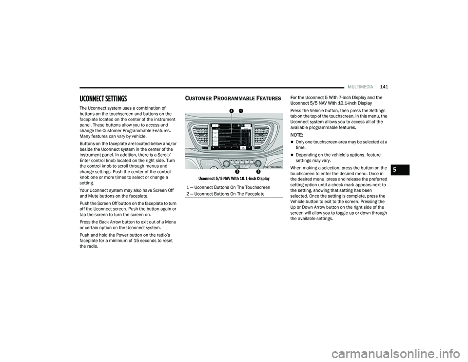
panel. These buttons allow you to access and
change the Customer Programmable Features.
Many features can vary by vehicle.
Buttons on the faceplate are located below and/or
beside the Uconnect system in the center of the
instrument panel. In addition, there is a Scroll/
Enter control knob located on the right side. Turn
the control knob to scroll through menus and
change settings. Push the center of the control
knob one or more times to select or change a
setting.
Your Uconnect system may also have Screen Off
and Mute buttons on the faceplate.
Push the Screen Off button on the faceplate to turn
off the Uconnect screen. Push the button again or
tap the screen to turn the screen on.
Press the Back Arrow button to exit out of a Menu
or certain option on the Uconnect system.
Push and hold the Power button on the radio’s
faceplate for a minimum of 15 seconds to reset
the radio.
CUSTOMER PROGRAMMABLE FEATURES
Uconnect 5/5 NAV With 10.1-inch Display
For the Uconnect 5 With 7-inch Display and the
Uconnect 5/5 NAV With 10.1-inch Display
Press the Vehicle button, then press the Settings
tab on the top of the touchscreen. In this menu, the
Uconnect system allows you to access all of the
available programmable features.
NOTE:
Only one touchscreen area may be selected at a
time.
Depending on the vehicle’s options, feature
settings may vary.
When making a selection, press the button on the
touchscreen to enter the desired menu. Once in
the desired menu, press and release the preferred
setting option until a check mark appears next to
the setting, showing that setting has been
selected. Once the setting is complete, press the
Vehicle button to exit to the screen. Pressing the
Up or Down Arrow button on the right side of the
screen will allow you to toggle up or down through
the available settings.
1 — Uconnect Buttons On The Touchscreen
2 — Uconnect Buttons On The Faceplate
5
22_RUVG_OM_EN_USC_t.book Page 141
Page 186 of 316
184SAFETY
Seat Belt Park Stitch — If Equipped
The rear outboard seat belts may be equipped with
a park stitch to raise the latch plate for easier
access to occupants. If the park stitch interferes
with the tight installation of a child restraint, slide
the latch plate over the stitching to shorten the lap
portion of the belt and install the car seat normally.
When the car seat is removed from the vehicle,
slide the latch plate above the park stitch to enable
occupants to latch the seat belt securely.
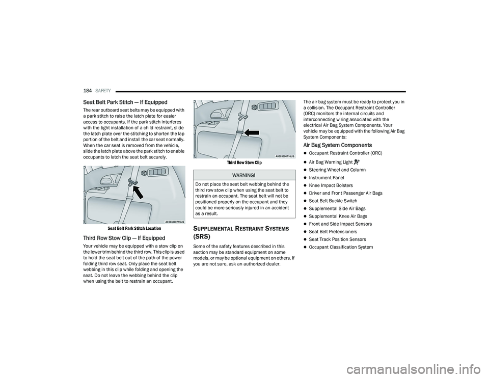
Seat Belt Park Stitch Location
Third Row Stow Clip — If Equipped
Your vehicle may be equipped with a stow clip on
the lower trim behind the third row. This clip is used
to hold the seat belt out of the path of the power
folding third row seat. Only place the seat belt
webbing in this clip while folding and opening the
seat. Do not leave the webbing behind the clip
when using the belt to restrain an occupant.
Third Row Stow Clip
SUPPLEMENTAL RESTRAINT SYSTEMS
(SRS)
Some of the safety features described in this
section may be standard equipment on some
models, or may be optional equipment on others. If
you are not sure, ask an authorized dealer. The air bag system must be ready to protect you in
a collision. The Occupant Restraint Controller
(ORC) monitors the internal circuits and
interconnecting wiring associated with the
electrical Air Bag System Components. Your
vehicle may be equipped with the following Air Bag
System Components:
Air Bag System Components
Occupant Restraint Controller (ORC)
Air Bag Warning Light
Steering Wheel and Column
Instrument Panel
Knee Impact Bolsters
Driver and Front Passenger Air Bags
Seat Belt Buckle Switch
Supplemental Side Air Bags
Supplemental Knee Air Bags
Front and Side Impact Sensors
Seat Belt Pretensioners
Seat Track Position Sensors
Occupant Classification System
WARNING!
Do not place the seat belt webbing behind the
third row stow clip when using the seat belt to
restrain an occupant. The seat belt will not be
positioned properly on the occupant and they
could be more seriously injured in an accident
as a result.
22_RUVG_OM_EN_USC_t.book Page 184
Page 187 of 316
SAFETY185
Air Bag Warning Light
The Occupant Restraint Controller (ORC)
monitors the readiness of the electronic
parts of the air bag system whenever the
ignition switch is in the START or ON/RUN
position. If the ignition switch is in the OFF position
or in the ACC position, the air bag system is not on
and the air bags will not inflate.
The ORC contains a backup power supply system
that may deploy the air bag system even if the
battery loses power or it becomes disconnected
prior to deployment.
The ORC turns on the Air Bag Warning Light in the
instrument panel for approximately four to eight
seconds for a self-check when the ignition switch is
first in the ON/RUN position. After the self-check,
the Air Bag Warning Light will turn off. If the ORC
detects a malfunction in any part of the system, it
turns on the Air Bag Warning Light, either
momentarily or continuously. A single chime will
sound to alert you if the light comes on again after
initial startup.
The ORC also includes diagnostics that will
illuminate the instrument panel Air Bag Warning
Light if a malfunction is detected that could affect
the air bag system. The diagnostics also record the nature of the malfunction. While the air bag system
is designed to be maintenance free, if any of the
following occurs, have an authorized dealer
service the air bag system immediately.
The Air Bag Warning Light does not come on
during the four to eight seconds when the igni
-
tion switch is first in the ON/RUN position.
The Air Bag Warning Light remains on after the
four to eight-second interval.
The Air Bag Warning Light comes on intermit -
tently or remains on while driving.
NOTE:If the speedometer, tachometer, or any engine
related gauges are not working, the Occupant
Restraint Controller (ORC) may also be disabled. In
this condition the air bags may not be ready to
inflate for your protection. Have an authorized
dealer service the air bag system immediately.
Redundant Air Bag Warning Light
If a fault with the Air Bag Warning Light is
detected, which could affect the
Supplemental Restraint System (SRS),
the Redundant Air Bag Warning Light will
illuminate on the instrument panel. The
Redundant Air Bag Warning Light will stay on until
the fault is cleared. In addition, a single chime will
sound to alert you that the Redundant Air Bag
Warning Light has come on and a fault has been
detected. If the Redundant Air Bag Warning Light
comes on intermittently or remains on while driving
have an authorized dealer service the vehicle
immediately
Úpage 95.
Front Air Bags
This vehicle has front air bags and lap/shoulder
belts for both the driver and front passenger. The
front air bags are a supplement to the seat belt
restraint systems. The driver front air bag is
mounted in the center of the steering wheel. The
passenger front air bag is mounted in the
instrument panel, above the glove compartment.
The words “SRS AIRBAG” or “AIRBAG” are
embossed on the air bag covers.
WARNING!
Ignoring the Air Bag Warning Light in your
instrument panel could mean you won’t have the
air bag system to protect you in a collision. If the
light does not come on as a bulb check when the
ignition is first turned on, stays on after you start
the vehicle, or if it comes on as you drive, have
an authorized dealer service the air bag system
immediately.
6
22_RUVG_OM_EN_USC_t.book Page 185
Page 188 of 316
186SAFETY
(Continued)
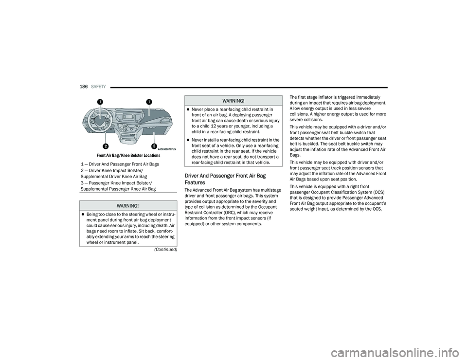
Front Air Bag/Knee Bolster Locations
Driver And Passenger Front Air Bag
Features
The Advanced Front Air Bag system has multistage
driver and front passenger air bags. This system
provides output appropriate to the severity and
type of collision as determined by the Occupant
Restraint Controller (ORC), which may receive
information from the front impact sensors (if
equipped) or other system components. The first stage inflator is triggered immediately
during an impact that requires air bag deployment.
A low energy output is used in less severe
collisions. A higher energy output is used for more
severe collisions.
This vehicle may be equipped with a driver and/or
front passenger seat belt buckle switch that
detects whether the driver or front passenger seat
belt is buckled. The seat belt buckle switch may
adjust the inflation rate of the Advanced Front Air
Bags.
This vehicle may be equipped with driver and/or
front passenger seat track position sensors that
may adjust the inflation rate of the Advanced Front
Air Bags based upon seat position.
This vehicle is equipped with a right front
passenger Occupant Classification System (OCS)
that is designed to provide Passenger Advanced
Front Air Bag output appropriate to the occupant’s
seated weight input, as determined by the OCS.
1 — Driver And Passenger Front Air Bags
2 — Driver Knee Impact Bolster/
Supplemental Driver Knee Air Bag
3 — Passenger Knee Impact Bolster/
Supplemental Passenger Knee Air Bag
WARNING!
Being too close to the steering wheel or instru
-
ment panel during front air bag deployment
could cause serious injury, including death. Air
bags need room to inflate. Sit back, comfort -
ably extending your arms to reach the steering
wheel or instrument panel.
Never place a rear-facing child restraint in
front of an air bag. A deploying passenger
front air bag can cause death or serious injury
to a child 12 years or younger, including a
child in a rear-facing child restraint.
Never install a rear-facing child restraint in the
front seat of a vehicle. Only use a rear-facing
child restraint in the rear seat. If the vehicle
does not have a rear seat, do not transport a
rear-facing child restraint in that vehicle.
WARNING!
22_RUVG_OM_EN_USC_t.book Page 186
Page 189 of 316

SAFETY187
Front Air Bag Operation
Front Air Bags are designed to provide additional
protection by supplementing the seat belts. Front
air bags are not expected to reduce the risk of
injury in rear, side, or rollover collisions. The front
air bags will not deploy in all frontal collisions,
including some that may produce substantial vehicle damage — for example, some pole
collisions, truck underrides, and angle offset
collisions.
On the other hand, depending on the type and
location of impact, front air bags may deploy in
crashes with little vehicle front-end damage but
that produce a severe initial deceleration.
Because air bag sensors measure vehicle
deceleration over time, vehicle speed and damage
by themselves are not good indicators of whether
or not an air bag should have deployed.
Seat belts are necessary for your protection in all
collisions, and also are needed to help keep you in
position, away from an inflating air bag.
When the Occupant Restraint Controller (ORC)
detects a collision requiring the front air bags, it
signals the inflator units. A large quantity of
non-toxic gas is generated to inflate the front air
bags.
The steering wheel hub trim cover and the upper
passenger side of the instrument panel separate
and fold out of the way as the air bags inflate to
their full size. The front air bags fully inflate in less
time than it takes to blink your eyes. The front air
bags then quickly deflate while helping to restrain
the driver and front passenger.
Occupant Classification System (OCS) —
Front Passenger Seat
The Occupant Classification System (OCS) is part of
a Federally regulated safety system for this vehicle.
It is designed to provide Passenger Advanced Front
Air Bag output appropriate to the occupant’s seated
weight, as determined by the OCS.
The Occupant Classification System (OCS) consists
of the following:
Occupant Restraint Controller (ORC)
Occupant Classification Module (OCM) and
Sensor located in the front passenger seat
Air Bag Warning Light
Occupant Classification Module (OCM) And Sensor
The Occupant Classification Module (OCM) is
located underneath the front passenger seat. The
Sensor is located beneath the passenger seat
cushion foam. Any weight on the seat will be sensed
by the Sensor. The OCM uses input from the Sensor
to determine the front passenger’s most probable
classification. The OCM communicates this
information to the ORC. The ORC may reduce the
inflation rate of the Passenger Advanced Front Air
Bag deployment based on occupant classification.
In order for the OCS to operate as designed, it is
important for the front passenger to be seated
properly and properly wearing the seat belt.
WARNING!
No objects should be placed over or near the
air bag on the instrument panel or steering
wheel because any such objects could cause
harm if the vehicle is in a collision severe
enough to cause the air bag to inflate.
Do not put anything on or around the air bag
covers or attempt to open them manually. You
may damage the air bags and you could be
injured because the air bags may no longer be
functional. The protective covers for the air
bag cushions are designed to open only when
the air bags are inflating.
Relying on the air bags alone could lead to
more severe injuries in a collision. The air
bags work with your seat belt to restrain you
properly. In some collisions, air bags won’t
deploy at all. Always wear your seat belts even
though you have air bags.6
22_RUVG_OM_EN_USC_t.book Page 187