Control panel CHRYSLER VOYAGER 2022 User Guide
[x] Cancel search | Manufacturer: CHRYSLER, Model Year: 2022, Model line: VOYAGER, Model: CHRYSLER VOYAGER 2022Pages: 316, PDF Size: 17.41 MB
Page 68 of 316
66GETTING TO KNOW YOUR VEHICLE
Outside Air Intake
Make sure the air intake, located directly in front of
the windshield, is free of obstructions, such as
leaves. Leaves collected in the air intake may
reduce airflow, and if they enter the air distribution
box, they could plug the water drains. In Winter
months, make sure the air intake is clear of ice,
slush, and snow.
Cabin Air Filter
The Climate Control system filters out dust and
pollen from the air. Contact an authorized dealer to
service your cabin air filter, and to have it replaced
when needed.
Operating Tips Chart
INTERIOR STORAGE AND EQUIPMENT
STORAGE
Glove Compartment
The glove compartment is located on the
passenger side of the instrument panel.
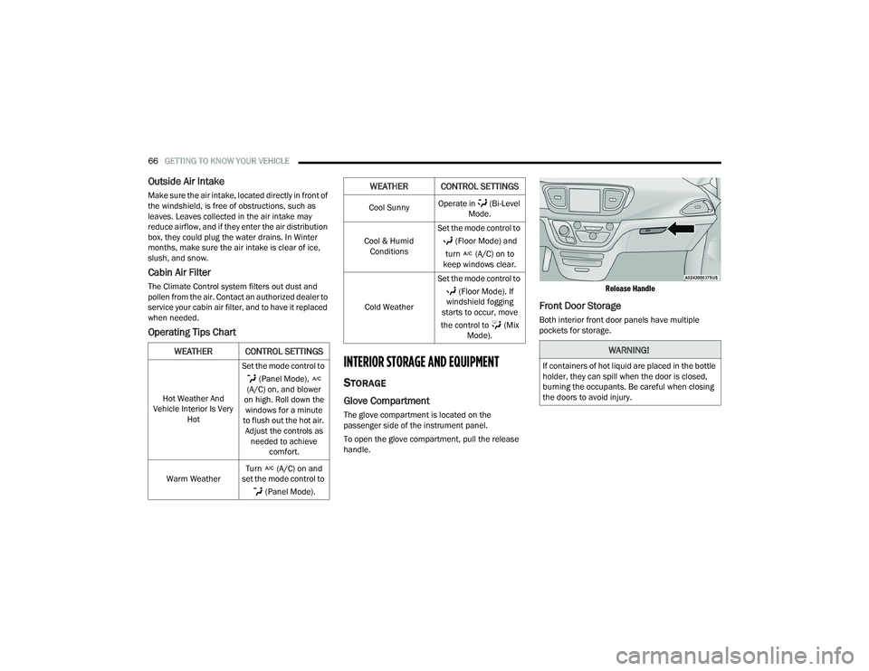
To open the glove compartment, pull the release
handle.
Release Handle
Front Door Storage
Both interior front door panels have multiple
pockets for storage.
WEATHER CONTROL SETTINGS
Hot Weather And
Vehicle Interior Is Very Hot Set the mode control to
(Panel Mode),
(A/C) on, and blower
on high. Roll down the windows for a minute
to flush out the hot air. Adjust the controls as needed to achieve comfort.
Warm Weather Turn (A/C) on and
set the mode control to
(Panel Mode).
Cool Sunny Operate in (Bi-Level
Mode.
Cool & Humid Conditions Set the mode control to
(Floor Mode) and
turn (A/C) on to
keep windows clear.
Cold Weather Set the mode control to
(Floor Mode). If
windshield fogging
starts to occur, move
the control to (Mix Mode).
WEATHER CONTROL SETTINGS
WARNING!
If containers of hot liquid are placed in the bottle
holder, they can spill when the door is closed,
burning the occupants. Be careful when closing
the doors to avoid injury.
22_RUVG_OM_EN_USC_t.book Page 66
Page 71 of 316
GETTING TO KNOW YOUR VEHICLE69
SEAT STORAGE BIN COVER EMERGENCY
RELEASE LEVER
As a security measure, the Seat Storage Bin Cover
has an Emergency Release Lever built into the
latching mechanism.
Storage Bin Cover Emergency Release Lever
NOTE:In the event of an individual being locked inside
the storage bin, the storage bin cover can be
opened from inside of the bin by pushing on the
glow-in-the-dark lever attached to the storage bin
cover latching mechanism.
SUN SCREENS — IF EQUIPPED
Sun screens are available for second row seating
windows. The screens store in the sill trim panels,
and the tops of the windows are equipped with
hooks that the sun screens attach to when pulled
out.
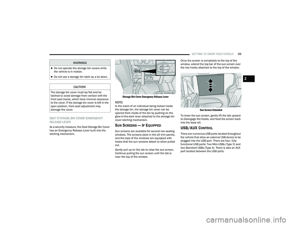
Gently pull up on the tab to raise the sun screen.
Continue pulling the sun screen until the tab is
near the top of the window.Once the screen is completely to the top of the
window, extend the top bar of the sun screen over
the two hooks attached to the top of the window.
Sun Screen Extended
To lower the sun screen, gently lift the tab upward
to disengage the hooks, and feed the screen back
into the base sill.USB/AUX CONTROL
There are numerous USB ports located throughout
the vehicle that allow an external USB device to be
plugged into the USB port. There are four, fully
functional USB ports: Two Mini-USBs (Type C) and
two Standard USBs (Type A). There is also an AUX
port located between the USB ports.
Do not operate the storage bin covers while
the vehicle is in motion.
Do not use a storage bin latch as a tie down.
CAUTION!
The storage bin cover must lay flat and be
latched to avoid damage from contact with the
front seat tracks, which have minimal clearance
to the cover. If the storage bin cover is left in the
open position, front seat adjustment may
damage the cover.
WARNING!
2
22_RUVG_OM_EN_USC_t.book Page 69
Page 74 of 316
72GETTING TO KNOW YOUR VEHICLE
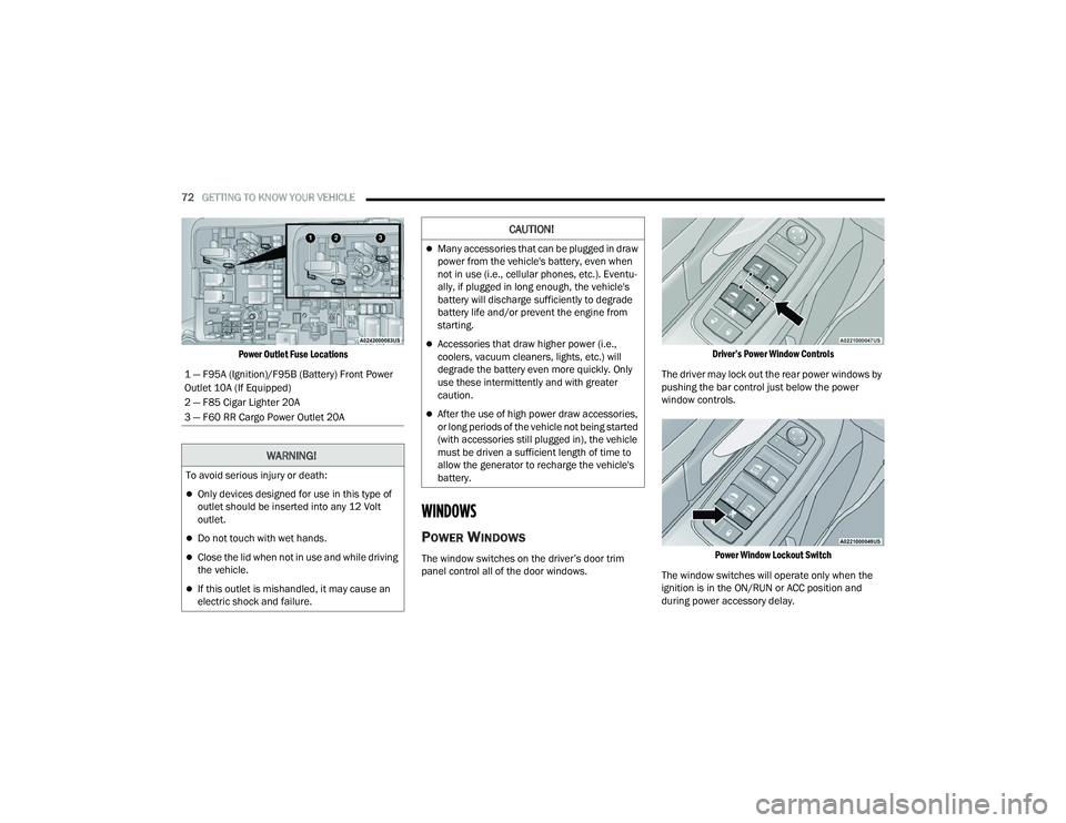
Power Outlet Fuse Locations
WINDOWS
POWER WINDOWS
The window switches on the driver’s door trim
panel control all of the door windows.
Driver’s Power Window Controls
The driver may lock out the rear power windows by
pushing the bar control just below the power
window controls.
Power Window Lockout Switch
The window switches will operate only when the
ignition is in the ON/RUN or ACC position and
during power accessory delay.
1 — F95A (Ignition)/F95B (Battery) Front Power
Outlet 10A (If Equipped)
2 — F85 Cigar Lighter 20A
3 — F60 RR Cargo Power Outlet 20A
WARNING!
To avoid serious injury or death:
Only devices designed for use in this type of
outlet should be inserted into any 12 Volt
outlet.
Do not touch with wet hands.
Close the lid when not in use and while driving
the vehicle.
If this outlet is mishandled, it may cause an
electric shock and failure.
CAUTION!
Many accessories that can be plugged in draw
power from the vehicle's battery, even when
not in use (i.e., cellular phones, etc.). Eventu
-
ally, if plugged in long enough, the vehicle's
battery will discharge sufficiently to degrade
battery life and/or prevent the engine from
starting.
Accessories that draw higher power (i.e.,
coolers, vacuum cleaners, lights, etc.) will
degrade the battery even more quickly. Only
use these intermittently and with greater
caution.
After the use of high power draw accessories,
or long periods of the vehicle not being started
(with accessories still plugged in), the vehicle
must be driven a sufficient length of time to
allow the generator to recharge the vehicle's
battery.
22_RUVG_OM_EN_USC_t.book Page 72
Page 75 of 316
GETTING TO KNOW YOUR VEHICLE73
NOTE:Power Window controls will also remain active for
up to 10 minutes after the ignition has been
placed in the OFF position, depending upon the
accessory delay setting. Opening a front door will
cancel this feature.
There is a single control on the front passenger’s
door trim panel which operates the passenger door
window and a set of controls that lock and unlock
all doors. The controls will operate only when the
ignition is in the ON/RUN or ACC position and
during power accessory delay.
Sliding Side Door Power Window Control —
If Equipped
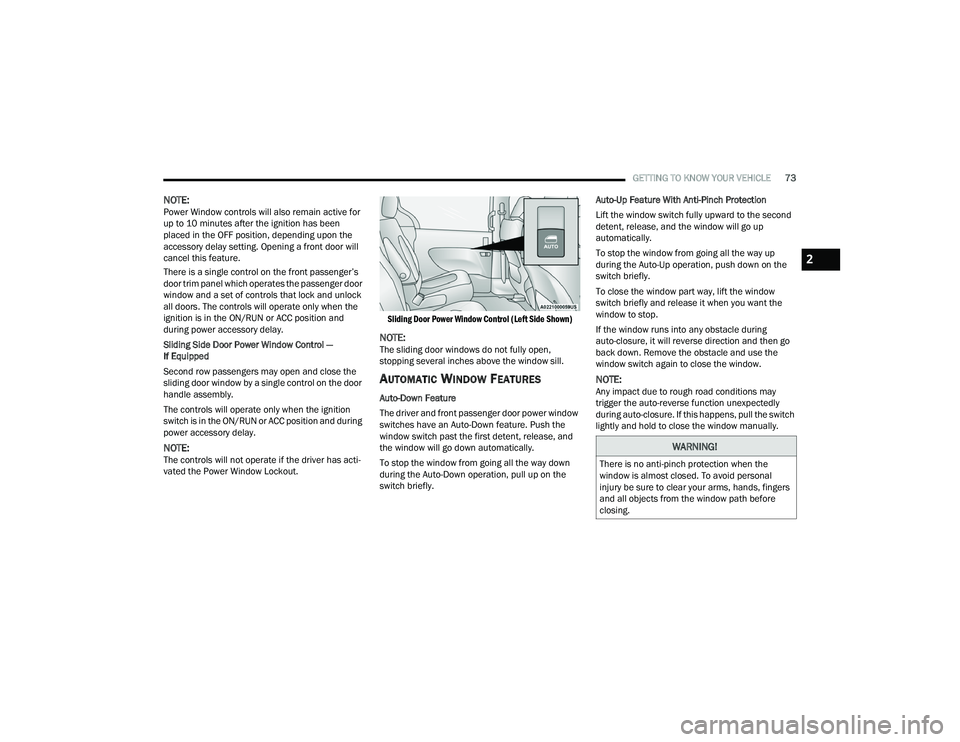
Second row passengers may open and close the
sliding door window by a single control on the door
handle assembly.
The controls will operate only when the ignition
switch is in the ON/RUN or ACC position and during
power accessory delay.
NOTE:The controls will not operate if the driver has acti-
vated the Power Window Lockout.
Sliding Door Power Window Control (Left Side Shown)
NOTE:The sliding door windows do not fully open,
stopping several inches above the window sill.
AUTOMATIC WINDOW FEATURES
Auto-Down Feature
The driver and front passenger door power window
switches have an Auto-Down feature. Push the
window switch past the first detent, release, and
the window will go down automatically.
To stop the window from going all the way down
during the Auto-Down operation, pull up on the
switch briefly.Auto-Up Feature With Anti-Pinch Protection
Lift the window switch fully upward to the second
detent, release, and the window will go up
automatically.
To stop the window from going all the way up
during the Auto-Up operation, push down on the
switch briefly.
To close the window part way, lift the window
switch briefly and release it when you want the
window to stop.
If the window runs into any obstacle during
auto-closure, it will reverse direction and then go
back down. Remove the obstacle and use the
window switch again to close the window.
NOTE:Any impact due to rough road conditions may
trigger the auto-reverse function unexpectedly
during auto-closure. If this happens, pull the switch
lightly and hold to close the window manually.
WARNING!
There is no anti-pinch protection when the
window is almost closed. To avoid personal
injury be sure to clear your arms, hands, fingers
and all objects from the window path before
closing.
2
22_RUVG_OM_EN_USC_t.book Page 73
Page 76 of 316
74GETTING TO KNOW YOUR VEHICLE
RESET AUTO UP
To reactivate the Auto Up feature, perform the
following steps after vehicle power is restored:
1. Pull the window control up to close the
window completely and continue to hold the
control up for an additional two seconds after
the window is closed.
2. Push the window control down firmly to the second detent to open the window completely
and continue to hold the control down for an
additional two seconds after the window is
fully open.
WIND BUFFETING
Wind buffeting can be described as the perception
of pressure on the ears or a helicopter-type sound
in the ears. Your vehicle may exhibit wind buffeting
with the windows down, or the sunroof (if
equipped) in certain open or partially open
positions. This is a normal occurrence and can be
minimized. If the buffeting occurs with the rear
windows open, open the front and rear windows
together to minimize the buffeting. If the buffeting
occurs with the sunroof open, adjust the sunroof
opening to minimize the buffeting or open any
window.
HOOD
OPENING
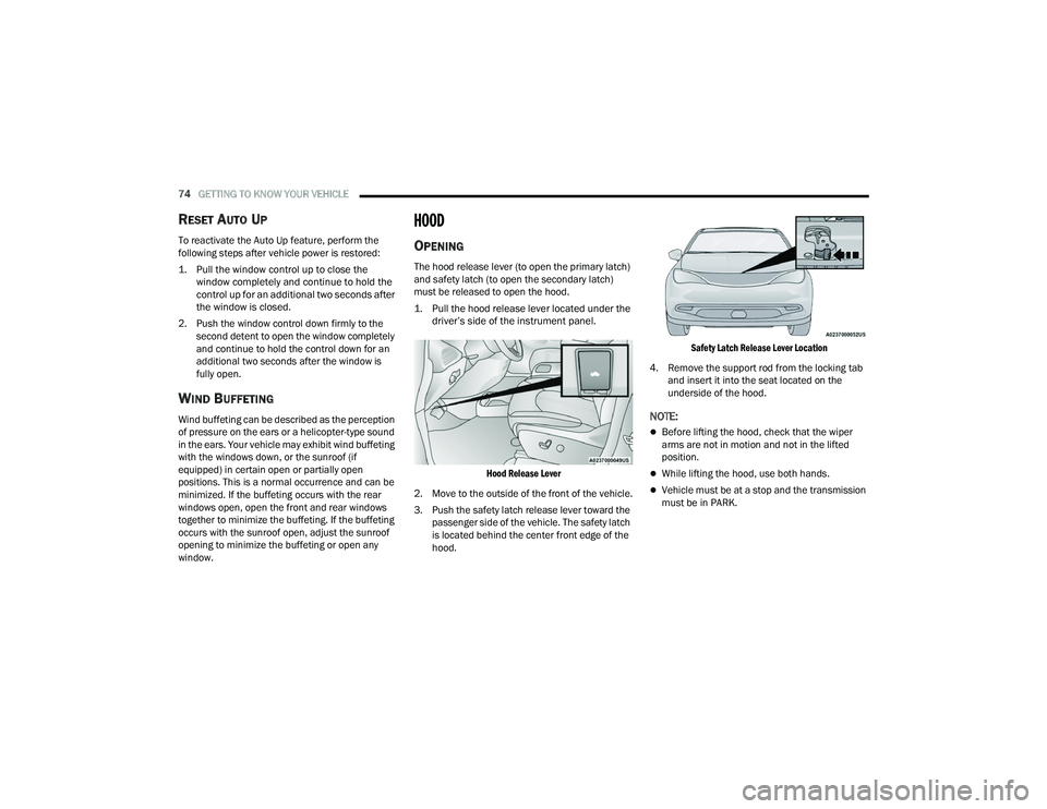
The hood release lever (to open the primary latch)
and safety latch (to open the secondary latch)
must be released to open the hood.
1. Pull the hood release lever located under the driver’s side of the instrument panel.
Hood Release Lever
2. Move to the outside of the front of the vehicle.
3. Push the safety latch release lever toward the passenger side of the vehicle. The safety latch
is located behind the center front edge of the
hood.
Safety Latch Release Lever Location
4. Remove the support rod from the locking tab and insert it into the seat located on the
underside of the hood.
NOTE:
Before lifting the hood, check that the wiper
arms are not in motion and not in the lifted
position.
While lifting the hood, use both hands.
Vehicle must be at a stop and the transmission
must be in PARK.
22_RUVG_OM_EN_USC_t.book Page 74
Page 83 of 316
GETTING TO KNOW YOUR VEHICLE81
(Continued)
NOTE:
To help control wind noise, stow the crossbars in
the side rails when they are not in use.
If any metallic object is placed over the satellite
radio antenna (if equipped), you may experience
interruption of satellite radio reception.
WARNING!
Cargo must be securely tied down before driving
your vehicle. Improperly secured loads can fly off
the vehicle, particularly at high speeds, resulting
in personal injury or property damage. Follow
the roof rack cautions when carrying cargo on
your roof rack.
CAUTION!
To prevent damage to the roof of your vehicle,
DO NOT carry any loads on the roof rack
without the crossbars deployed. The load
should be secured and placed on top of the
crossbars, not directly on the roof. If it is
necessary to place the load on the roof, place
a blanket or other protective layer between
the load and the roof surface.
To avoid damage to the roof rack and vehicle,
do not exceed the maximum roof rack load
capacity of 150 lb (68 kg). Always distribute
heavy loads as evenly as possible and secure
the load appropriately.
Load should always be secured to cross bars
first, with tie down loops used as additional
securing points if needed. Tie loops are
intended as supplementary tie down points
only. Do not use ratcheting mechanisms with
the tie loops. Check the straps and thumb
wheels frequently to be sure that the load
remains securely attached.
Long loads that extend over the windshield,
such as wood panels or surfboards, or loads
with large frontal area should be secured to
both the front and rear of the vehicle.
Travel at reduced speeds and turn corners
carefully when carrying large or heavy loads
on the roof rack. Wind forces, due to natural
causes or nearby truck traffic, can add sudden
upward lift to a load. This is especially true on
large flat loads and may result in damage to
the cargo or your vehicle.
CAUTION!
2
22_RUVG_OM_EN_USC_t.book Page 81
Page 87 of 316
GETTING TO KNOW YOUR INSTRUMENT PANEL85
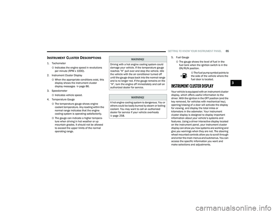
INSTRUMENT CLUSTER DESCRIPTIONS
1. Tachometer
Indicates the engine speed in revolutions
per minute (RPM x 1000).
2. Instrument Cluster Display
When the appropriate conditions exist, this
display shows the instrument cluster
display messages
Úpage 86.
3. Speedometer
Indicates vehicle speed.
4. Temperature Gauge
The temperature gauge shows engine
coolant temperature. Any reading within the
normal range indicates that the engine
cooling system is operating satisfactorily.
The gauge can indicate a higher tempera -
ture when driving in hot weather or up
mountain grades. It should not be allowed
to exceed the upper limits of the normal
operating range. 5. Fuel Gauge
The gauge shows the level of fuel in the
fuel tank when the ignition switch is in the
ON/RUN position.
The fuel pump symbol points to
the side of the vehicle where the
fuel door is located.
INSTRUMENT CLUSTER DISPLAY
Your vehicle is equipped with an instrument cluster
display, which offers useful information to the
driver. With the ignition in the OFF position (and the
key removed, for vehicles with mechanical key),
opening/closing of a door will activate the display
for viewing, and display the total miles or
kilometers in the odometer. Your instrument
cluster display is designed to display important
information about your vehicle’s systems and
features. Using a driver interactive display located
on the instrument panel, your instrument cluster
display can show you how systems are working and
give you warnings when they are not. The steering
wheel mounted controls allow you to scroll through
and enter the main menus and submenus. You can
access the specific information you want and
make selections and adjustments.
WARNING!
Driving with a hot engine cooling system could
damage your vehicle. If the temperature gauge
reaches “H” pull over and stop the vehicle. Idle
the vehicle with the air conditioner turned off
until the gauge drops back into the normal range
and is no longer red. If the gauge remains on the
“H”, turn the engine off immediately and call an
authorized dealer for service.
WARNING!
A hot engine cooling system is dangerous. You or
others could be badly burned by steam or boiling
coolant. You may want to call an authorized
dealer for service if your vehicle overheats
Úpage 258.
3
22_RUVG_OM_EN_USC_t.book Page 85
Page 88 of 316
86GETTING TO KNOW YOUR INSTRUMENT PANEL
INSTRUMENT CLUSTER DISPLAY
L
OCATION AND CONTROLS
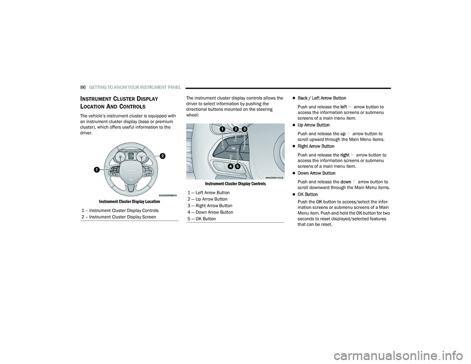
The vehicle’s instrument cluster is equipped with
an instrument cluster display (base or premium
cluster), which offers useful information to the
driver.
Instrument Cluster Display Location
The instrument cluster display controls allows the
driver to select information by pushing the
directional buttons mounted on the steering
wheel:
Instrument Cluster Display Controls
Back / Left Arrow Button
Push and release the left arrow button to
access the information screens or submenu
screens of a main menu item.
Up Arrow Button
Push and release the up arrow button to
scroll upward through the Main Menu items.
Right Arrow Button
Push and release the right arrow button to
access the information screens or submenu
screens of a main menu item.
Down Arrow Button
Push and release the down arrow button to
scroll downward through the Main Menu items.
OK Button
Push the OK button to access/select the infor -
mation screens or submenu screens of a Main
Menu item. Push and hold the OK button for two
seconds to reset displayed/selected features
that can be reset.
1 – Instrument Cluster Display Controls
2 – Instrument Cluster Display Screen1 — Left Arrow Button
2 — Up Arrow Button
3 — Right Arrow Button
4 — Down Arrow Button
5 — OK Button
22_RUVG_OM_EN_USC_t.book Page 86
Page 97 of 316
GETTING TO KNOW YOUR INSTRUMENT PANEL95
Trip B
Shows the total distance traveled for Trip B
since the last reset.
Shows the Average MPG for Trip B since the last
reset.
Shows the elapsed time traveled for Trip B since
the last reset. Elapsed time will increment when
the ignition switch is in the ON or START posi -
tion.
To Reset A Trip Function
Push and hold the OK button to reset the currently
displayed trip.
WARNING LIGHTS AND MESSAGES
The warning/indicator lights will illuminate in the
instrument panel together with a dedicated
message and/or acoustic signal when applicable.
These indications are indicative and precautionary
and as such must not be considered as exhaustive
and/or alternative to the information contained in
the Owner’s Manual, which you are advised to read
carefully in all cases. Always refer to the
information in this chapter in the event of a failure
indication. All active warning/indicator lights will
display first if applicable. The system check menu
may appear different based upon equipment
options and current vehicle status. Some warning/
indicator lights are optional and may not appear.
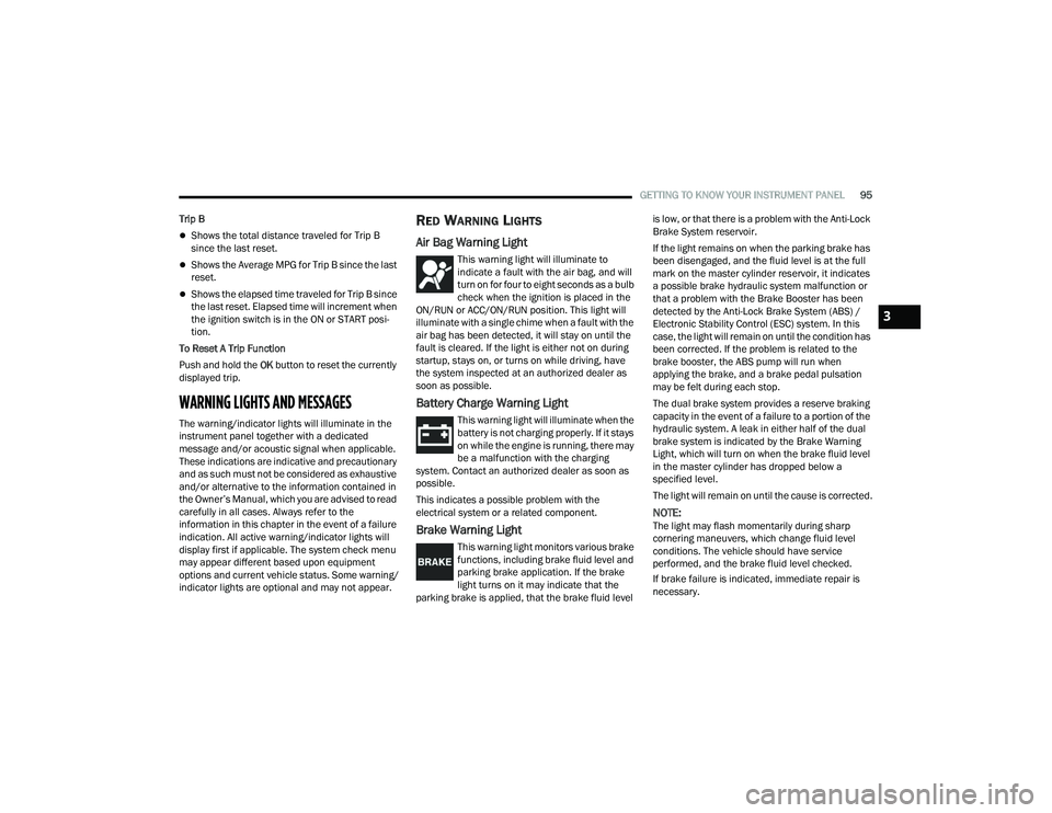
RED WARNING LIGHTS
Air Bag Warning Light
This warning light will illuminate to
indicate a fault with the air bag, and will
turn on for four to eight seconds as a bulb
check when the ignition is placed in the
ON/RUN or ACC/ON/RUN position. This light will
illuminate with a single chime when a fault with the
air bag has been detected, it will stay on until the
fault is cleared. If the light is either not on during
startup, stays on, or turns on while driving, have
the system inspected at an authorized dealer as
soon as possible.
Battery Charge Warning Light
This warning light will illuminate when the
battery is not charging properly. If it stays
on while the engine is running, there may
be a malfunction with the charging
system. Contact an authorized dealer as soon as
possible.
This indicates a possible problem with the
electrical system or a related component.
Brake Warning Light
This warning light monitors various brake
functions, including brake fluid level and
parking brake application. If the brake
light turns on it may indicate that the
parking brake is applied, that the brake fluid level is low, or that there is a problem with the Anti-Lock
Brake System reservoir.
If the light remains on when the parking brake has
been disengaged, and the fluid level is at the full
mark on the master cylinder reservoir, it indicates
a possible brake hydraulic system malfunction or
that a problem with the Brake Booster has been
detected by the Anti-Lock Brake System (ABS) /
Electronic Stability Control (ESC) system. In this
case, the light will remain on until the condition has
been corrected. If the problem is related to the
brake booster, the ABS pump will run when
applying the brake, and a brake pedal pulsation
may be felt during each stop.
The dual brake system provides a reserve braking
capacity in the event of a failure to a portion of the
hydraulic system. A leak in either half of the dual
brake system is indicated by the Brake Warning
Light, which will turn on when the brake fluid level
in the master cylinder has dropped below a
specified level.
The light will remain on until the cause is corrected.
NOTE:The light may flash momentarily during sharp
cornering maneuvers, which change fluid level
conditions. The vehicle should have service
performed, and the brake fluid level checked.
If brake failure is indicated, immediate repair is
necessary.
3
22_RUVG_OM_EN_USC_t.book Page 95
Page 98 of 316
96GETTING TO KNOW YOUR INSTRUMENT PANEL
Vehicles equipped with the Anti-Lock Brake System
(ABS) are also equipped with Electronic Brake
Force Distribution (EBD). In the event of an EBD
failure, the Brake Warning Light will turn on along
with the ABS Light. Immediate repair to the ABS
system is required.
Operation of the Brake Warning Light can be
checked by turning the ignition switch from the OFF
position to the ON/RUN position. The light should
illuminate for approximately two seconds. The light
should then turn off unless the parking brake is
applied or a brake fault is detected. If the light does
not illuminate, have the light inspected by an
authorized dealer.
The light also will turn on when the parking brake
is applied with the ignition switch in the ON/RUN
position.
NOTE:This light shows only that the parking brake is
applied. It does not show the degree of brake appli -
cation.
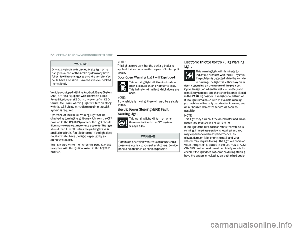
Door Open Warning Light — If Equipped
This warning light will illuminate when a
door is ajar/open and not fully closed.
This indicator will reflect which doors are
open.
NOTE:If the vehicle is moving, there will also be a single
chime.
Electric Power Steering (EPS) Fault
Warning Light
This warning light will turn on when
there's a fault with the EPS system
Úpage 116.
Electronic Throttle Control (ETC) Warning
Light
This warning light will illuminate to
indicate a problem with the ETC system.
If a problem is detected while the vehicle
is running, the light will either stay on or
flash depending on the nature of the problem.
Cycle the ignition when the vehicle is safely and
completely stopped and the transmission is placed
in the PARK (P) position. The light should turn off.
If the light remains on with the vehicle running,
your vehicle will usually be drivable; however, see
an authorized dealer for service as soon as
possible.
NOTE:This light may turn on if the accelerator and brake
pedals are pressed at the same time.
If the light continues to flash when the vehicle is
running, immediate service is required and you
may experience reduced performance, an
elevated/rough idle, or engine stall and your
vehicle may require towing. The light will come on
when the ignition is placed in the ON/RUN or ACC/
ON/RUN position and remain on briefly as a bulb
check. If the light does not come on during starting,
have the system checked by an authorized dealer.
WARNING!
Driving a vehicle with the red brake light on is
dangerous. Part of the brake system may have
failed. It will take longer to stop the vehicle. You
could have a collision. Have the vehicle checked
immediately.
WARNING!
Continued operation with reduced assist could
pose a safety risk to yourself and others. Service
should be obtained as soon as possible.
22_RUVG_OM_EN_USC_t.book Page 96