ABS CHRYSLER VOYAGER 2023 Owners Manual
[x] Cancel search | Manufacturer: CHRYSLER, Model Year: 2023, Model line: VOYAGER, Model: CHRYSLER VOYAGER 2023Pages: 256, PDF Size: 13.97 MB
Page 6 of 256
4
MULTIMEDIA
UCONNECT SYSTEMS ..................................................... 104
CYBERSECURITY ............................................................. 104
UCONNECT SETTINGS...................................................... 105
Customer Programmable Features ........................ 105
RADIO OPERATION AND MOBILE PHONES .................. 120 Regulatory And Safety Information .......................... 120
SAFETY
SAFETY FEATURES........................................................... 121Anti-Lock Brake System (ABS) ................................. 121Rear Seat Reminder Alert (RSRA) ............................ 121
Electronic Brake Control (EBC) System .................. 122
AUXILIARY DRIVING SYSTEMS ...................................... 126 Blind Spot Monitoring (BSM) — If Equipped ............ 126Forward Collision Warning (FCW) With
Mitigation — If Equipped ........................................... 129
Tire Pressure Monitoring
System (TPMS) .......................................................... 131
OCCUPANT RESTRAINT SYSTEMS ................................ 134 Occupant Restraint Systems Features ................... 134Important Safety Precautions .................................. 134Seat Belt Systems .................................................... 135
Supplemental Restraint Systems (SRS) .................. 143Child Restraints ......................................................... 153 SAFETY TIPS .................................................................... 167
Transporting Passengers ......................................... 167
Transporting Pets .................................................... 167
Connected Vehicles .................................................. 167Safety Checks You Should Make Inside
The Vehicle ............................................................... 167Periodic Safety Checks You Should Make
Outside The Vehicle .................................................. 168Exhaust Gas ............................................................. 169
Carbon Monoxide Warnings ..................................... 169IN CASE OF EMERGENCY
HAZARD WARNING FLASHERS ..................................... 170
SOS AND ASSIST MIRROR — IF EQUIPPED ................. 170
JACKING AND TIRE CHANGING —
IF EQUIPPED .................................................................... 173 Preparations For Jacking ......................................... 173
Jack And Spare Tire Location................................... 174Equipment Removal ................................................ 174
Jacking Instructions.................................................. 175Road Tire Installation ............................................... 178
Portable Air Compressor — If Equipped .................. 179
Return Inflatable Spare Tire..................................... 180
TIRE SERVICE KIT — IF EQUIPPED ................................. 180
JUMP STARTING............................................................... 185 Preparations For Jump Start .................................... 185Jump Starting Procedure.......................................... 186 REFUELING IN EMERGENCY – IF EQUIPPED ...............187
IF YOUR ENGINE OVERHEATS......................................... 187
MANUAL PARK RELEASE ...............................................188
FREEING A STUCK VEHICLE ........................................... 189
TOWING A DISABLED VEHICLE.......................................190
ENHANCED ACCIDENT RESPONSE
SYSTEM (EARS) ...............................................................191
EVENT DATA RECORDER (EDR)......................................191
SERVICING AND MAINTENANCE
SCHEDULED SERVICING ................................................. 192 Maintenance Plan ..................................................... 193
ENGINE COMPARTMENT ................................................. 195 3.6L Engine................................................................ 195
Checking Oil Level ..................................................... 196Adding Washer Fluid ................................................ 196
Maintenance-Free Battery ........................................ 196Pressure Washing ..................................................... 197
VEHICLE MAINTENANCE ................................................. 197 Engine Oil .................................................................. 197
Engine Oil Filter ......................................................... 197
Engine Air Cleaner Filter .......................................... 198
Accessory Drive Belt Inspection ............................... 198Air Conditioner Maintenance .................................... 199
Body Lubrication........................................................ 200
Windshield Wiper Blades .......................................... 201
23_RUV_OM_EN_US_t.book Page 4
Page 10 of 256
8
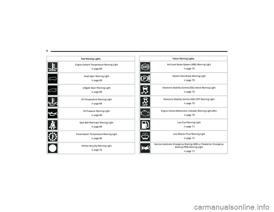
Engine Coolant Temperature Warning Light
Úpage 69
Hood Open Warning Light
Úpage 69
Liftgate Open Warning Light
Úpage 69
Oil Temperature Warning Light
Úpage 69
Oil Pressure Warning Light
Úpage 69
Seat Belt Reminder Warning Light
Úpage 69
Transmission Temperature Warning Light
Úpage 69
Vehicle Security Warning Light
Úpage 70
Red Warning Lights
Yellow Warning Lights
Anti-Lock Brake System (ABS) Warning Light
Úpage 70
Electric Park Brake Warning Light
Úpage 70
Electronic Stability Control (ESC) Active Warning Light
Úpage 70
Electronic Stability Control (ESC) OFF Warning Light
Úpage 70
Engine Check/Malfunction Indicator Warning Light (MIL)
Úpage 70
Low Fuel Warning Light
Úpage 71
Low Washer Fluid Warning Light
Úpage 71
Service Automatic Emergency Braking (AEB) or Pedestrian Emergency Braking (PEB) Warning Light
Úpage 71
23_RUV_OM_EN_US_t.book Page 8
Page 13 of 256
GETTING TO KNOW YOUR VEHICLE11
Key Left Vehicle Feature
If a valid key fob is no longer detected inside the vehicle
while the vehicle’s ignition system is in the ON/RUN or
START position, the message “Key Fob Has Left The
Vehicle” will be shown in the instrument cluster display
along with an interior chime. An exterior audible and visual
alert will also be activated to warn the driver.
The vehicle’s horn will rapidly chirp three times along with
a single flash of the vehicle’s exterior lights.
NOTE:
The doors have to be open and then closed in order for
the vehicle to check for the presence of a key fob; the
Key Left Vehicle feature will not activate until all of the
doors are closed.
These alerts will not be activated in situations where
the vehicle’s engine is left running with the key fob
inside.
Replacing The Battery In The Key Fob
The recommended replacement battery is one CR2032
battery.
NOTE:
Customers are recommended to use a battery
obtained from Mopar®. Aftermarket coin battery
dimensions may not meet the original OEM coin battery
dimensions.
Batteries contain harmful chemicals. Dispose old
batteries by placing them in correct containers
according to the law or by taking them to a dealership,
where they will be handled appropriately.
Perchlorate Material — special handling may apply.
See www.dtsc.ca.gov/hazardouswaste/perchlorate for
further information.
Do not touch the battery terminals that are on the back
housing or the printed circuit board.
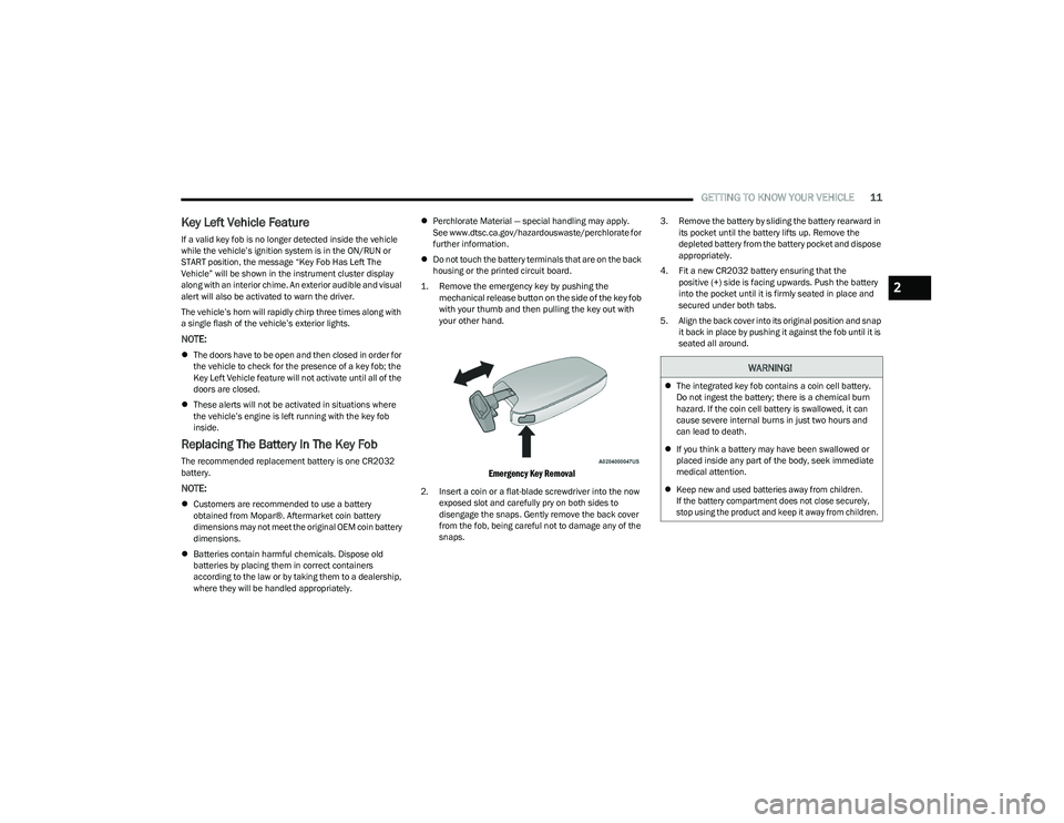
1. Remove the emergency key by pushing the mechanical release button on the side of the key fob
with your thumb and then pulling the key out with
your other hand.
Emergency Key Removal
2. Insert a coin or a flat-blade screwdriver into the now exposed slot and carefully pry on both sides to
disengage the snaps. Gently remove the back cover
from the fob, being careful not to damage any of the
snaps. 3. Remove the battery by sliding the battery rearward in
its pocket until the battery lifts up. Remove the
depleted battery from the battery pocket and dispose
appropriately.
4. Fit a new CR2032 battery ensuring that the positive (+) side is facing upwards. Push the battery
into the pocket until it is firmly seated in place and
secured under both tabs.
5. Align the back cover into its original position and snap it back in place by pushing it against the fob until it is
seated all around.
WARNING!
The integrated key fob contains a coin cell battery.
Do not ingest the battery; there is a chemical burn
hazard. If the coin cell battery is swallowed, it can
cause severe internal burns in just two hours and
can lead to death.
If you think a battery may have been swallowed or
placed inside any part of the body, seek immediate
medical attention.
Keep new and used batteries away from children.
If the battery compartment does not close securely,
stop using the product and keep it away from children.
2
23_RUV_OM_EN_US_t.book Page 11
Page 70 of 256
68GETTING TO KNOW YOUR INSTRUMENT PANEL
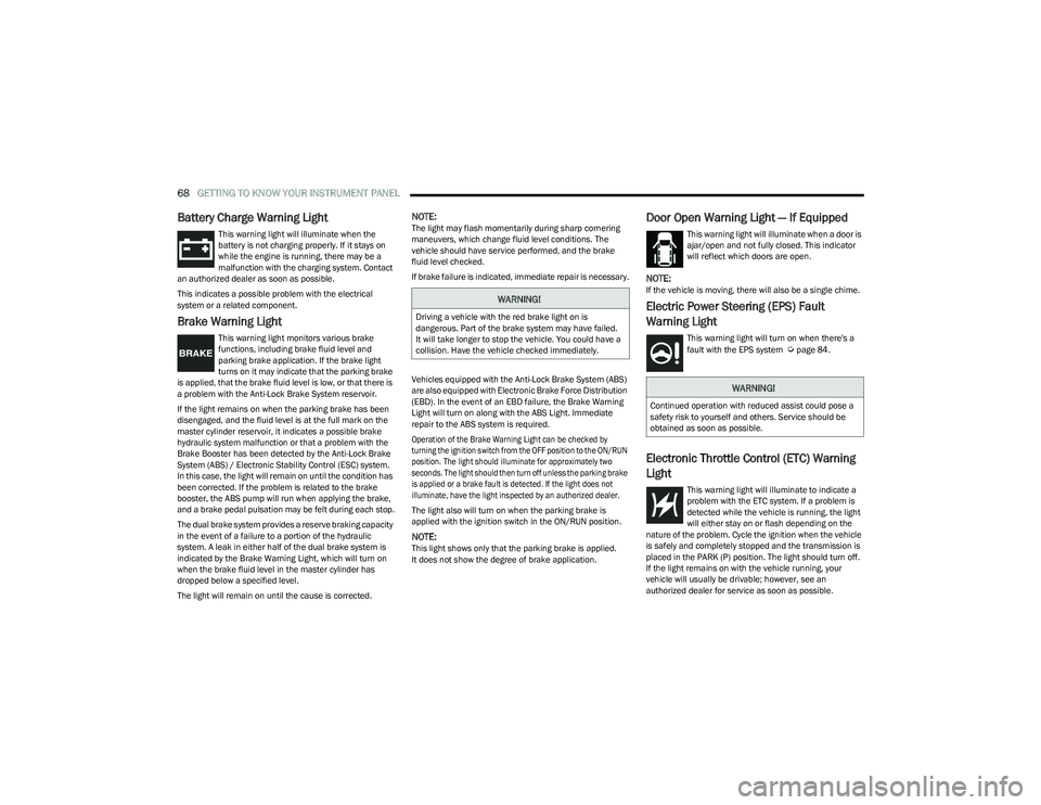
Battery Charge Warning Light
This warning light will illuminate when the
battery is not charging properly. If it stays on
while the engine is running, there may be a
malfunction with the charging system. Contact
an authorized dealer as soon as possible.
This indicates a possible problem with the electrical
system or a related component.
Brake Warning Light
This warning light monitors various brake
functions, including brake fluid level and
parking brake application. If the brake light
turns on it may indicate that the parking brake
is applied, that the brake fluid level is low, or that there is
a problem with the Anti-Lock Brake System reservoir.
If the light remains on when the parking brake has been
disengaged, and the fluid level is at the full mark on the
master cylinder reservoir, it indicates a possible brake
hydraulic system malfunction or that a problem with the
Brake Booster has been detected by the Anti-Lock Brake
System (ABS) / Electronic Stability Control (ESC) system.
In this case, the light will remain on until the condition has
been corrected. If the problem is related to the brake
booster, the ABS pump will run when applying the brake,
and a brake pedal pulsation may be felt during each stop.
The dual brake system provides a reserve braking capacity
in the event of a failure to a portion of the hydraulic
system. A leak in either half of the dual brake system is
indicated by the Brake Warning Light, which will turn on
when the brake fluid level in the master cylinder has
dropped below a specified level.
The light will remain on until the cause is corrected.
NOTE:The light may flash momentarily during sharp cornering
maneuvers, which change fluid level conditions. The
vehicle should have service performed, and the brake
fluid level checked.
If brake failure is indicated, immediate repair is necessary.
Vehicles equipped with the Anti-Lock Brake System (ABS)
are also equipped with Electronic Brake Force Distribution
(EBD). In the event of an EBD failure, the Brake Warning
Light will turn on along with the ABS Light. Immediate
repair to the ABS system is required.
Operation of the Brake Warning Light can be checked by
turning the ignition switch from the OFF position to the ON/RUN
position. The light should illuminate for approximately two
seconds. The light should then turn off unless the parking brake
is applied or a brake fault is detected. If the light does not
illuminate, have the light inspected by an authorized dealer.
The light also will turn on when the parking brake is
applied with the ignition switch in the ON/RUN position.
NOTE:This light shows only that the parking brake is applied.
It does not show the degree of brake application.
Door Open Warning Light — If Equipped
This warning light will illuminate when a door is
ajar/open and not fully closed. This indicator
will reflect which doors are open.
NOTE:If the vehicle is moving, there will also be a single chime.
Electric Power Steering (EPS) Fault
Warning Light
This warning light will turn on when there's a
fault with the EPS system Úpage 84.
Electronic Throttle Control (ETC) Warning
Light
This warning light will illuminate to indicate a
problem with the ETC system. If a problem is
detected while the vehicle is running, the light
will either stay on or flash depending on the
nature of the problem. Cycle the ignition when the vehicle
is safely and completely stopped and the transmission is
placed in the PARK (P) position. The light should turn off.
If the light remains on with the vehicle running, your
vehicle will usually be drivable; however, see an
authorized dealer for service as soon as possible.
WARNING!
Driving a vehicle with the red brake light on is
dangerous. Part of the brake system may have failed.
It will take longer to stop the vehicle. You could have a
collision. Have the vehicle checked immediately.
WARNING!
Continued operation with reduced assist could pose a
safety risk to yourself and others. Service should be
obtained as soon as possible.
23_RUV_OM_EN_US_t.book Page 68
Page 72 of 256
70GETTING TO KNOW YOUR INSTRUMENT PANEL
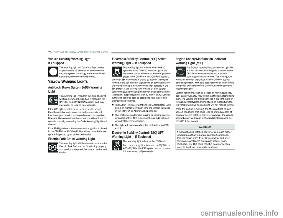
Vehicle Security Warning Light —
If Equipped
This warning light will flash at a fast rate for
approximately 15 seconds when the vehicle
security system is arming, and then will flash
slowly until the vehicle is disarmed.
YELLOW WARNING LIGHTS
Anti-Lock Brake System (ABS) Warning
Light
This warning light monitors the ABS. The light
will turn on when the ignition is placed in the
ON/RUN or ACC/ON/RUN position and may
stay on for as long as four seconds.
If the ABS light remains on or turns on while driving,
then the Anti-Lock portion of the brake system is not
functioning and service is required as soon as possible.
However, the conventional brake system will continue to
operate normally, assuming the Brake Warning Light is not
also on.
If the ABS light does not turn on when the ignition is placed
in the ON/RUN or ACC/ON/RUN position, have the brake
system inspected by an authorized dealer.
Electric Park Brake Warning Light
This warning light will illuminate to indicate the
Electric Park Brake is not functioning properly
and service is required. Contact an authorized
dealer.
Electronic Stability Control (ESC) Active
Warning Light — If Equipped
This warning light will indicate when the ESC
system is Active. The ESC Indicator Light in the
instrument cluster will come on when the ignition is
placed in the ON/RUN or ACC/ON/RUN position,
and when ESC is activated. It should go out with the engine
running. If the ESC Indicator Light comes on continuously with
the engine running, a malfunction has been detected in the
ESC system. If this warning light remains on after several
ignition cycles, and the vehicle has been driven several miles
(kilometers) at speeds greater than 30 mph (48 km/h), see an
authorized dealer as soon as possible to have the problem
diagnosed and corrected.
The ESC OFF Indicator Light and the ESC Indicator Light
come on momentarily each time the ignition is placed
in the ON/RUN or ACC/ON/RUN position.
The ESC system will make buzzing or clicking sounds
when it is active. This is normal; the sounds will stop
when ESC becomes inactive.
This light will come on when the vehicle is in an ESC
event.
Electronic Stability Control (ESC) OFF
Warning Light — If Equipped
This warning light indicates the ESC is off.
Each time the ignition is turned to ON/RUN or
ACC/ON/RUN, the ESC system will be on, even
if it was turned off previously.
Engine Check/Malfunction Indicator
Warning Light (MIL)
The Engine Check/Malfunction Indicator Light (MIL)
is a part of an Onboard Diagnostic System called
OBD II that monitors engine and automatic
transmission control systems. This warning light
will illuminate when the ignition is in the ON/RUN position
before engine start. If the bulb does not come on when turning
the ignition switch from OFF to ON/RUN, have the condition
checked promptly.
Certain conditions, such as a loose or missing gas cap,
poor quality fuel, etc., may illuminate the light after engine
start. The vehicle should be serviced if the light stays on
through several typical driving styles. In most situations,
the vehicle will drive normally and will not require towing.
When the engine is running, the MIL may flash to alert
serious conditions that could lead to immediate loss of
power or severe catalytic converter damage. The vehicle
should be serviced by an authorized dealer as soon as
possible if this occurs.
WARNING!
A malfunctioning catalytic converter can reach higher
temperatures than in normal operating conditions.
This can cause a fire if you drive slowly or park over
flammable substances such as dry plants, wood,
cardboard, etc. This could result in death or serious
injury to the driver, occupants or others.
23_RUV_OM_EN_US_t.book Page 70
Page 123 of 256
121
SAFETY
SAFETY FEATURES
ANTI-LOCK BRAKE SYSTEM (ABS)
The ABS provides increased vehicle stability and brake
performance under most braking conditions. The system
automatically prevents wheel lock and enhances vehicle
control during braking.
The ABS performs a self-check cycle to ensure that the
ABS is working properly each time the vehicle is started
and driven. During this self-check, you may hear a slight
clicking sound as well as some related motor noises.
The ABS is activated during braking when the system
detects one or more wheels are beginning to lock. Road
conditions such as ice, snow, gravel, bumps, railroad
tracks, loose debris, or panic stops may increase the
likelihood of ABS activation(s).
You also may experience the following normal
characteristics when the ABS activates:
ABS motor noise or clicking sounds (you may continue
to hear for a short time after the stop)
Brake pedal pulsations
A slight drop of the brake pedal at the end of the stop
The ABS is designed to function with the Original
Equipment Manufacturer (OEM) tires. Modification may
result in degraded ABS performance.
Anti-Lock Brake System (ABS) Warning
Light
The yellow ABS Warning Light will turn on when the ignition
is placed in the ON/RUN mode and may stay on for as long
as four seconds.
If the ABS Warning Light remains on or comes on while
driving, it indicates that the anti-lock portion of the brake
system is not functioning and that service is required.
However, the conventional brake system will continue to
operate normally if the ABS Warning Light is on.
If the ABS Warning Light is on, the brake system should be
serviced as soon as possible to restore the benefits of
Anti-Lock Brakes. If the ABS Warning Light does not come
on when the ignition is placed in the ON/RUN mode, have
the light repaired as soon as possible.
REAR SEAT REMINDER ALERT (RSRA)
RSRA alerts of the possible presence of an object, passenger,
or pet in the rear seats through a visual and auditory
notification. When the system is activated, it displays the
message “Check Rear Seat” on the instrument cluster display
and sounds an auditory alert upon the driver placing the
ignition in the OFF position to exit the vehicle. The system
will activate automatically if a rear door is opened within
10 minutes of the ignition being placed in the ON/RUN position.
RSRA should be used as a reminder to check the rear seats, it
does not directly detect objects, passengers, or pets and is only
activated when the previous conditions are met.
WARNING!
The ABS contains sophisticated electronic equip -
ment that may be susceptible to interference caused
by improperly installed or high output radio transmit -
ting equipment. This interference can cause possible
loss of anti-lock braking capability. Installation of
such equipment should be performed by qualified
professionals.
Pumping of the Anti-Lock Brakes will diminish their
effectiveness and may lead to a collision. Pumping
makes the stopping distance longer. Just press firmly
on your brake pedal when you need to slow down
or stop.
The ABS cannot prevent the natural laws of physics
from acting on the vehicle, nor can it increase
braking or steering efficiency beyond that afforded
by the condition of the vehicle brakes and tires or the
traction afforded.
The ABS cannot prevent collisions, including those
resulting from excessive speed in turns, following
another vehicle too closely, or hydroplaning.
The capabilities of an ABS equipped vehicle must
never be exploited in a reckless or dangerous
manner that could jeopardize the user’s safety
or the safety of others.
6
23_RUV_OM_EN_US_t.book Page 121
Page 124 of 256
122SAFETY
To enable or disable RSRA, see Úpage 105.
ELECTRONIC BRAKE CONTROL (EBC)
S
YSTEM
Your vehicle is equipped with an advanced Electronic
Brake Control (EBC) system. This system includes
Anti-Lock Brake System (ABS), Brake Assist System (BAS),
Electronic Brake Force Distribution (EBD), Electronic
Roll Mitigation (ERM), Electronic Stability Control (ESC),
Hill Start Assist (HSA), and Traction Control System
(TCS).These systems work together to enhance both
vehicle stability and control in various driving conditions. Your vehicle may also be equipped with Dynamic Steering
Torque (DST), Ready Alert Braking (RAB), Rain Brake
Support (RBS) and Trailer Sway Control (TSC).
Brake Assist System (BAS)
The BAS is designed to optimize the vehicle’s braking capability
during emergency braking maneuvers. The system detects an
emergency braking situation by sensing the rate and amount of
brake application and then applies optimum pressure to the
brakes. This can help reduce braking distances. The BAS
complements the Anti-Lock Brake System (ABS). Applying the
brakes very quickly results in the best BAS assistance.
To receive the benefit of the system, you must apply continuous
braking pressure during the stopping sequence (do not “pump”
the brakes). Do not reduce brake pedal pressure unless
braking is no longer desired. Once the brake pedal is released,
the BAS is deactivated.
Brake System Warning Light
The red Brake System Warning Light will turn on when the
ignition is placed in the ON/RUN mode and may stay on for
as long as four seconds.
If the Brake System Warning Light remains on or comes on
while driving, it indicates that the brake system is not
functioning properly and that immediate service is
required. If the Brake System Warning Light does not
come on when the ignition is placed in the ON/RUN mode,
have the light repaired as soon as possible.
Dynamic Steering Torque (DST)
DST is a feature of the ESC and Electric Power Steering
(EPS) modules that provides torque at the steering wheel
for certain driving conditions in which the ESC module is
detecting vehicle instability. The torque that the steering
wheel receives is only meant to help the driver realize
optimal steering behavior in order to reach/maintain
vehicle stability. The only notification the driver receives
that the feature is active is the torque applied to the
steering wheel.
NOTE:The DST feature is only meant to help the driver realize the
correct course of action through small torques on the
steering wheel, which means the effectiveness of the DST
feature is highly dependent on the driver’s sensitivity and
overall reaction to the applied torque. It is very important
to realize that this feature will not steer the vehicle,
meaning the driver is still responsible for steering the
vehicle.
WARNING!
Before exiting a vehicle, always come to a complete
stop, then shift the automatic transmission into
PARK and apply the parking brake.
Always make sure the keyless ignition node is in the
OFF position, key fob is removed from the vehicle
and vehicle is locked.
Never leave children alone in a vehicle, or with
access to an unlocked vehicle. Leaving children in
a vehicle unattended is dangerous for a number of
reasons. A child or others could be seriously or fatally
injured. Children should be warned not to touch the
parking brake, brake pedal or the gear selector.
Do not leave children or animals inside parked vehi -
cles in hot weather. Interior heat buildup may cause
serious injury or death.
WARNING!
The Brake Assist System (BAS) cannot prevent the natural
laws of physics from acting on the vehicle, nor can it
increase the traction afforded by prevailing road conditions.
BAS cannot prevent collisions, including those resulting from
excessive speed in turns, driving on very slippery surfaces,
or hydroplaning. The capabilities of a BAS-equipped vehicle
must never be exploited in a reckless or dangerous manner,
which could jeopardize the user's safety or the safety of
others.
23_RUV_OM_EN_US_t.book Page 122
Page 125 of 256

SAFETY123
Electronic Brake Force Distribution (EBD)
The EBD function manages the distribution of the braking
torque between the front and rear axles by limiting braking
pressure to the rear axle. This is done to prevent overslip
of the rear wheels to avoid vehicle instability, and to
prevent the rear axle from entering the Anti-Lock Brake
System (ABS) before the front axle.
Electronic Roll Mitigation (ERM)
ERM anticipates the potential for wheel lift by monitoring the
driver’s steering wheel input and the speed of the vehicle.
When ERM determines that the rate of change of the steering
wheel angle and vehicle’s speed are sufficient to potentially
cause wheel lift, it then applies the appropriate brake and may
also reduce engine power to lessen the chance that wheel lift
will occur. ERM can only reduce the chance of wheel lift
occurring during severe or evasive driving maneuvers; it cannot
prevent wheel lift due to other factors, such as road conditions,
leaving the roadway, striking objects or other vehicles.
Electronic Stability Control (ESC)
ESC enhances directional control and stability of the
vehicle under various driving conditions. ESC corrects for
oversteering or understeering of the vehicle by applying
the brake of the appropriate wheel(s) to assist in
counteracting these conditions. Engine power may also be
reduced to help the vehicle maintain the desired path.
Oversteer — when the vehicle is turning more than
appropriate for the steering wheel position.
Understeer — when the vehicle is turning less than
appropriate for the steering wheel position.
ESC uses sensors in the vehicle to determine the vehicle
path intended by the driver and compares it to the
actual path of the vehicle. When the actual path does not
match the intended path, ESC applies the brake of the
appropriate wheel to assist in counteracting the oversteer
or understeer condition.
The ESC Activation/Malfunction Indicator Light located in
the instrument cluster will start to flash as soon as the ESC
system becomes active. The ESC Activation/Malfunction
Indicator Light also flashes when the TCS is active. If the
ESC Activation/Malfunction Indicator Light begins to flash
during acceleration, ease up on the accelerator and apply
as little throttle as possible. Be sure to adapt your speed
and driving to the prevailing road conditions.
WARNING!
Many factors, such as vehicle loading, road conditions and
driving conditions, influence the chance that wheel lift or
rollover may occur. ERM cannot prevent all wheel lift or
rollovers, especially those that involve leaving the roadway
or striking objects or other vehicles. The capabilities of an
ERM-equipped vehicle must never be exploited in a reckless
or dangerous manner which could jeopardize the user's
safety or the safety of others.
WARNING!
Electronic Stability Control (ESC) cannot prevent the
natural laws of physics from acting on the vehicle, nor can
it increase the traction afforded by prevailing road condi -
tions. ESC cannot prevent accidents, including those
resulting from excessive speed in turns, driving on very
slippery surfaces, or hydroplaning. ESC also cannot
prevent accidents resulting from loss of vehicle control
due to inappropriate driver input for the conditions. Only
a safe, attentive, and skillful driver can prevent accidents.
The capabilities of an ESC equipped vehicle must never
be exploited in a reckless or dangerous manner which
could jeopardize the user’s safety or the safety of others.
Vehicle modifications, or failure to properly maintain
your vehicle, may change the handling characteris -
tics of your vehicle, and may negatively affect the
performance of the ESC system. Changes to the
steering system, suspension, braking system, tire
type and size or wheel size may adversely affect ESC
performance. Improperly inflated and unevenly worn
tires may also degrade ESC performance. Any vehicle
modification or poor vehicle maintenance that
reduces the effectiveness of the ESC system can
increase the risk of loss of vehicle control, vehicle
rollover, personal injury and death.
6
23_RUV_OM_EN_US_t.book Page 123
Page 151 of 256
SAFETY149
The following requirements must be strictly followed:
Do not modify the front passenger seat assembly or
components in any way.
Do not use prior or future model year seat covers or
cushions not designated by FCA US LLC for the specific
model being repaired. Always use the correct seat
cover and cushion specified for the vehicle.
Do not replace the seat cover or cushion with an after -
market seat cover or cushion.
Do not add a secondary seat cover or mat.
At no time should any Supplemental Restraint
System (SRS) component or SRS related component or
fastener be modified or replaced with any part except
those which are approved by FCA US LLC.Knee Impact Bolsters
The Knee Impact Bolsters help protect the knees of
the driver and front passenger, and position the front
occupants for improved interaction with the front air bags.
Supplemental Driver And Front Passenger
Knee Air Bags
This vehicle is equipped with a Supplemental Driver Knee Air
Bag mounted in the instrument panel below the steering
column and a Supplemental Passenger Knee Air Bag mounted
in the instrument panel below the glove compartment. The
Supplemental Knee Air Bags provide enhanced protection
during a frontal impact by working together with the seat belts,
pretensioners, and front air bags.
Supplemental Side Air Bags
Supplemental Seat-Mounted Side Air Bags (SABs)
This vehicle is equipped with Supplemental Seat-Mounted
Side Air Bags (SABs).
Supplemental Seat-Mounted Side Air Bags (SABs) are
located in the outboard side of the front seats. The SABs
are marked with “SRS AIRBAG” or “AIRBAG” on a label or
on the seat trim on the outboard side of the seats. The SABs may help to reduce the risk of occupant injury
during certain side impacts, in addition to the injury
reduction potential provided by the seat belts and body
structure.
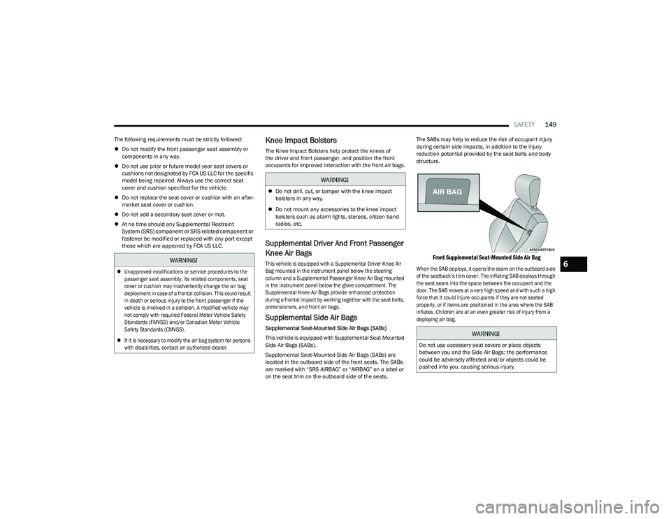
Front Supplemental Seat-Mounted Side Air Bag
When the SAB deploys, it opens the seam on the outboard side
of the seatback’s trim cover. The inflating SAB deploys through
the seat seam into the space between the occupant and the
door. The SAB moves at a very high speed and with such a high
force that it could injure occupants if they are not seated
properly, or if items are positioned in the area where the SAB
inflates. Children are at an even greater risk of injury from a
deploying air bag.
WARNING!
Unapproved modifications or service procedures to the
passenger seat assembly, its related components, seat
cover or cushion may inadvertently change the air bag
deployment in case of a frontal collision. This could result
in death or serious injury to the front passenger if the
vehicle is involved in a collision. A modified vehicle may
not comply with required Federal Motor Vehicle Safety
Standards (FMVSS) and/or Canadian Motor Vehicle
Safety Standards (CMVSS).
If it is necessary to modify the air bag system for persons
with disabilities, contact an authorized dealer.
WARNING!
Do not drill, cut, or tamper with the knee impact
bolsters in any way.
Do not mount any accessories to the knee impact
bolsters such as alarm lights, stereos, citizen band
radios, etc.
WARNING!
Do not use accessory seat covers or place objects
between you and the Side Air Bags; the performance
could be adversely affected and/or objects could be
pushed into you, causing serious injury.
6
23_RUV_OM_EN_US_t.book Page 149
Page 184 of 256
182IN CASE OF EMERGENCY
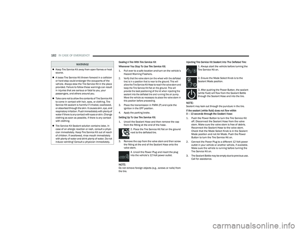
Sealing A Tire With Tire Service Kit
Whenever You Stop To Use Tire Service Kit:
1. Pull over to a safe location and turn on the vehicle’s
Hazard Warning Flashers.
2. Verify that the valve stem (on the wheel with the deflated tire) is in a position that is near to the ground. This will
allow the Tire Service Kit Hose to reach the valve stem and
keep the Tire Service Kit flat on the ground. This will
provide the best positioning of the kit when injecting the
sealant into the deflated tire and running the air pump.
Move the vehicle as necessary to place the valve stem in
this position before proceeding.
3. Place the transmission in PARK (P) and cycle the ignition in the OFF position.
4. Apply the parking brake.
Setting Up To Use Tire Service Kit:
1. Uncoil the Sealant Hose and then remove the cap from the fitting at the end of the hose.
2. Place the Tire Service Kit flat on the ground
next to the deflated tire.
3. Remove the cap from the valve stem and then screw the fitting at the end of the Sealant Hose onto the
valve stem.
4. Uncoil the Power Plug and insert the plug
into the vehicle’s 12 Volt power outlet.
NOTE:Do not remove foreign objects (e.g., screws or nails) from
the tire. Injecting Tire Service Kit Sealant Into The Deflated Tire:
1. Always start the vehicle before turning the
Tire Service Kit on.
2. Ensure the Mode Select Knob is to the
Sealant Mode position.
3. After pushing the Power Button, the sealant
(white fluid) will flow from the Sealant Bottle
through the Sealant Hose and into the tire.
NOTE:Sealant may leak out through the puncture in the tire.
If the sealant (white fluid) does not flow within
0 – 10 seconds through the Sealant Hose:
1. Push the Power Button to turn the Tire Service Kit off. Disconnect the Sealant Hose from the valve
stem. Make sure the valve stem is free of debris.
Reconnect the Sealant Hose to the valve stem.
Check that the Mode Select Knob is in the Sealant
Mode position and not Air Mode. Push the Power
Button to turn the Tire Service Kit on.
2. Connect the Power Plug to a different 12 Volt power outlet in your vehicle or another vehicle, if available.
Make sure the vehicle is running before turning the
Tire Service Kit on.
3. The Sealant Bottle may be empty due to previous use. Call for assistance.
Keep Tire Service Kit away from open flames or heat
source.
A loose Tire Service Kit thrown forward in a collision
or hard stop could endanger the occupants of the
vehicle. Always stow the Tire Service Kit in the place
provided. Failure to follow these warnings can result
in injuries that are serious or fatal to you, your
passengers, and others around you.
Take care not to allow the contents of Tire Service Kit
to come in contact with hair, eyes, or clothing. Tire
Service Kit sealant is harmful if inhaled, swallowed,
or absorbed through the skin. It causes skin, eye, and
respiratory irritation. Flush immediately with plenty of
water if there is any contact with eyes or skin. Change
clothing as soon as possible, if there is any contact
with clothing.
Tire Service Kit Sealant solution contains latex. In
case of an allergic reaction or rash, consult a physi -
cian immediately. Keep Tire Service Kit out of reach
of children. If swallowed, rinse mouth immediately
with plenty of water and drink plenty of water. Do not
induce vomiting! Consult a physician immediately.
WARNING!
23_RUV_OM_EN_US_t.book Page 182