suspension CHRYSLER VOYAGER 2023 Owners Manual
[x] Cancel search | Manufacturer: CHRYSLER, Model Year: 2023, Model line: VOYAGER, Model: CHRYSLER VOYAGER 2023Pages: 256, PDF Size: 13.97 MB
Page 96 of 256
94STARTING AND OPERATING
Payload
The payload of a vehicle is defined as the allowable load
weight a truck can carry, including the weight of the driver,
all passengers, options and cargo.
Gross Axle Weight Rating (GAWR)
The GAWR is the maximum permissible load on the front
and rear axles. The load must be distributed in the cargo
area so that the GAWR of each axle is not exceeded.
Each axle GAWR is determined by the components in
the system with the lowest load carrying capacity (axle,
springs, tires or wheels). Heavier axles or suspension
components sometimes specified by purchasers for
increased durability do not necessarily increase the
vehicle's GVWR.
Tire Size
The tire size on the Vehicle Certification Label represents
the actual tire size on your vehicle. Replacement tires
must be equal to the load capacity of this tire size.
Rim Size
This is the rim size that is appropriate for the tire size
listed.
Inflation Pressure
This is the cold tire inflation pressure for your vehicle for
all loading conditions up to full GAWR.
Curb Weight
The curb weight of a vehicle is defined as the total weight
of the vehicle with all fluids, including vehicle fuel, at full
capacity conditions, and with no occupants or cargo
loaded into the vehicle. The front and rear curb weight values are determined by weighing your vehicle on a
commercial scale before any occupants or cargo are
added.
Loading
The actual total weight and the weight of the front and rear
of your vehicle at the ground can best be determined by
weighing it when it is loaded and ready for operation.
The entire vehicle should first be weighed on a commercial
scale to ensure that the GVWR has not been exceeded.
The weight on the front and rear of the vehicle should then
be determined separately to be sure that the load is
properly distributed over the front and rear axle. Weighing
the vehicle may show that the GAWR of either the front or
rear axles has been exceeded but the total load is within
the specified GVWR. If so, weight must be shifted from
front to rear or rear to front as appropriate until the
specified weight limitations are met. Store the heavier
items down low and be sure that the weight is distributed
equally. Stow all loose items securely before driving.
Improper weight distributions can have an adverse effect
on the way your vehicle steers and handles and the way
the brakes operate.
TRAILER TOWING
In this section you will find safety tips and information on
limits to the type of towing you can reasonably do with your
vehicle. Before towing a trailer, carefully review this
information to tow your load as efficiently and safely as
possible.
To maintain the New Vehicle Limited Warranty coverage,
follow the requirements and recommendations in this
manual concerning vehicles used for trailer towing.
COMMON TOWING DEFINITIONS
The following trailer towing related definitions will assist
you in understanding the following information:
Gross Vehicle Weight Rating (GVWR)
GVWR is the total allowable weight of your vehicle. This
includes driver, passengers, cargo and tongue weight.
The total load must be limited so that you do not exceed
the GVWR
Úpage 93.
Gross Trailer Weight (GTW)
GTW is the weight of the trailer plus the weight of all cargo,
consumables and equipment (permanent or temporary)
loaded in or on the trailer in its "loaded and ready for
operation" condition.
The recommended way to measure GTW is to put your fully
loaded trailer on a vehicle scale. The entire weight of the
trailer must be supported by the scale.
WARNING!
Do not load your vehicle any heavier than the GVWR or
the maximum front and rear GAWR. If you do, parts on
your vehicle can break, or it can change the way your
vehicle handles. This could cause you to lose control.
Overloading can shorten the life of your vehicle.
23_RUV_OM_EN_US_t.book Page 94
Page 125 of 256

SAFETY123
Electronic Brake Force Distribution (EBD)
The EBD function manages the distribution of the braking
torque between the front and rear axles by limiting braking
pressure to the rear axle. This is done to prevent overslip
of the rear wheels to avoid vehicle instability, and to
prevent the rear axle from entering the Anti-Lock Brake
System (ABS) before the front axle.
Electronic Roll Mitigation (ERM)
ERM anticipates the potential for wheel lift by monitoring the
driver’s steering wheel input and the speed of the vehicle.
When ERM determines that the rate of change of the steering
wheel angle and vehicle’s speed are sufficient to potentially
cause wheel lift, it then applies the appropriate brake and may
also reduce engine power to lessen the chance that wheel lift
will occur. ERM can only reduce the chance of wheel lift
occurring during severe or evasive driving maneuvers; it cannot
prevent wheel lift due to other factors, such as road conditions,
leaving the roadway, striking objects or other vehicles.
Electronic Stability Control (ESC)
ESC enhances directional control and stability of the
vehicle under various driving conditions. ESC corrects for
oversteering or understeering of the vehicle by applying
the brake of the appropriate wheel(s) to assist in
counteracting these conditions. Engine power may also be
reduced to help the vehicle maintain the desired path.
Oversteer — when the vehicle is turning more than
appropriate for the steering wheel position.
Understeer — when the vehicle is turning less than
appropriate for the steering wheel position.
ESC uses sensors in the vehicle to determine the vehicle
path intended by the driver and compares it to the
actual path of the vehicle. When the actual path does not
match the intended path, ESC applies the brake of the
appropriate wheel to assist in counteracting the oversteer
or understeer condition.
The ESC Activation/Malfunction Indicator Light located in
the instrument cluster will start to flash as soon as the ESC
system becomes active. The ESC Activation/Malfunction
Indicator Light also flashes when the TCS is active. If the
ESC Activation/Malfunction Indicator Light begins to flash
during acceleration, ease up on the accelerator and apply
as little throttle as possible. Be sure to adapt your speed
and driving to the prevailing road conditions.
WARNING!
Many factors, such as vehicle loading, road conditions and
driving conditions, influence the chance that wheel lift or
rollover may occur. ERM cannot prevent all wheel lift or
rollovers, especially those that involve leaving the roadway
or striking objects or other vehicles. The capabilities of an
ERM-equipped vehicle must never be exploited in a reckless
or dangerous manner which could jeopardize the user's
safety or the safety of others.
WARNING!
Electronic Stability Control (ESC) cannot prevent the
natural laws of physics from acting on the vehicle, nor can
it increase the traction afforded by prevailing road condi -
tions. ESC cannot prevent accidents, including those
resulting from excessive speed in turns, driving on very
slippery surfaces, or hydroplaning. ESC also cannot
prevent accidents resulting from loss of vehicle control
due to inappropriate driver input for the conditions. Only
a safe, attentive, and skillful driver can prevent accidents.
The capabilities of an ESC equipped vehicle must never
be exploited in a reckless or dangerous manner which
could jeopardize the user’s safety or the safety of others.
Vehicle modifications, or failure to properly maintain
your vehicle, may change the handling characteris -
tics of your vehicle, and may negatively affect the
performance of the ESC system. Changes to the
steering system, suspension, braking system, tire
type and size or wheel size may adversely affect ESC
performance. Improperly inflated and unevenly worn
tires may also degrade ESC performance. Any vehicle
modification or poor vehicle maintenance that
reduces the effectiveness of the ESC system can
increase the risk of loss of vehicle control, vehicle
rollover, personal injury and death.
6
23_RUV_OM_EN_US_t.book Page 123
Page 193 of 256
IN CASE OF EMERGENCY191
(Continued)
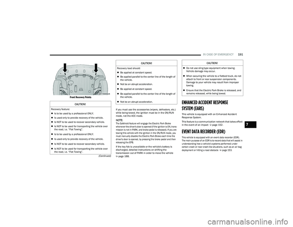
Front Recovery Points
If you must use the accessories (wipers, defrosters, etc.)
while being towed, the ignition must be in the ON/RUN
mode, not the ACC mode.
NOTE:
The Safehold feature will engage the Electric Park Brake
whenever the driver's door is opened (if the ignition is ON, trans -
mission is not in PARK, and brake pedal is released). If you are
towing this vehicle with the ignition in the ON/RUN mode, you
must manually disable the Electric Park Brake each time the
driver's door is opened, by pressing the brake pedal and then
releasing the EPB.
If the key fob is unavailable or the vehicle's battery is
discharged, detailed instructions on shifting the
transmission out of PARK in order to move the vehicle
Úpage 188.
ENHANCED ACCIDENT RESPONSE
SYSTEM (EARS)
This vehicle is equipped with an Enhanced Accident
Response System.
This feature is a communication network that takes effect
in the event of an impact
Úpage 152.
EVENT DATA RECORDER (EDR)
This vehicle is equipped with an event data recorder (EDR).
The main purpose of an EDR is to record data that will assist in
understanding how a vehicle’s systems performed under
certain crash or near crash-like situations, such as an air bag
deployment or hitting a road obstacle
Ú
page 153.
CAUTION!
Recovery feature:
Is to be used by a professional ONLY.
Is used only to provide recovery of the vehicle.
Is NOT to be used to recover secondary vehicle.
Is NOT to be used for transporting the vehicle over
the road, i.e. “Flat Towing”.
Is to be used by a professional ONLY.
Is used only to provide recovery of the vehicle.
Is NOT to be used to recover secondary vehicle.
Is NOT to be used for transporting the vehicle over
the road, i.e. “Flat Towing”.
Recovery load should:
Be applied at constant speed.
Be applied parallel to the center line of the length of
the vehicle.
Not be an abrupt acceleration.
Be applied at constant speed.
Be applied parallel to the center line of the length of
the vehicle.
Not be an abrupt acceleration.
CAUTION!CAUTION!
Do not use sling-type equipment when towing.
Vehicle damage may occur.
When securing the vehicle to a flatbed truck, do not
attach to front or rear suspension components.
Damage to your vehicle may result from improper
towing.
Ensure that the Electric Park Brake is released, and
remains released, while being towed.
7
23_RUV_OM_EN_US_t.book Page 191
Page 195 of 256
SERVICING AND MAINTENANCE193
MAINTENANCE PLAN
Refer to the Maintenance Plan for required maintenance.
At Every Oil Change Interval As Indicated By Oil Change Indicator System
Change oil and filter.
Rotate the tires at the first sign of irregular wear, even if it occurs before the oil indicator system turns on.
Inspect battery and clean and tighten terminals as required.
Inspect the CV/Universal joints.
Inspect brake pads, shoes, rotors, drums, hoses and parking brake.
Inspect engine cooling system protection and hoses.
Inspect exhaust system.
Inspect engine air cleaner filter if using in dusty or off-road conditions. If required, replace engine air cleaner filter.
Mileage Or Time Passed (Whichever Comes First)20,000
30,000
40,000
50,000
60,000
70,000
80,000
90,000
100,000
110,000
120,000
130,000
140,000
150,000
Or Years: 2 3 4 5 6 7 8 9 10 11 12 13 14 15
Or Kilometers:
32,000
48,000
64,000
80,000
96,000
112,000
128,000
144,000
160,000
176,000
192,000
208,000
224,000
240,000
Additional Inspections
Inspect the CV/Universal joints. X X X X X X X X X X X X X X
Inspect front suspension, boot seals, tie rod ends, and replace if necessary. X X X X X X X
Inspect the brake linings, parking brake function. X X X X X X X
Inspect front accessory drive tensioner, idler pulley, and replace if necessary. X
8
23_RUV_OM_EN_US_t.book Page 193
Page 229 of 256
SERVICING AND MAINTENANCE227
TIRE TYPES
All Season Tires — If Equipped
All season tires provide traction for all seasons (Spring,
Summer, Autumn, and Winter). Traction levels may vary
between different all season tires. All season tires can
be identified by the M+S, M&S, M/S or MS designation on
the tire sidewall. Use all season tires only in sets of four;
failure to do so may adversely affect the safety and
handling of your vehicle.
Summer Or Three Season Tires —
If Equipped
Summer tires provide traction in both wet and dry
conditions, and are not intended to be driven in snow or on
ice. If your vehicle is equipped with Summer tires, be
aware these tires are not designed for Winter or cold
driving conditions. Install Winter tires on your vehicle when
ambient temperatures are less than 40°F (5°C) or if
roads are covered with ice or snow. For more information,
contact an authorized dealer.
Summer tires do not contain the all season designation or
mountain/snowflake symbol on the tire sidewall. Use
Summer tires only in sets of four; failure to do so may
adversely affect the safety and handling of your vehicle.
Snow Tires
Some areas of the country require the use of snow tires
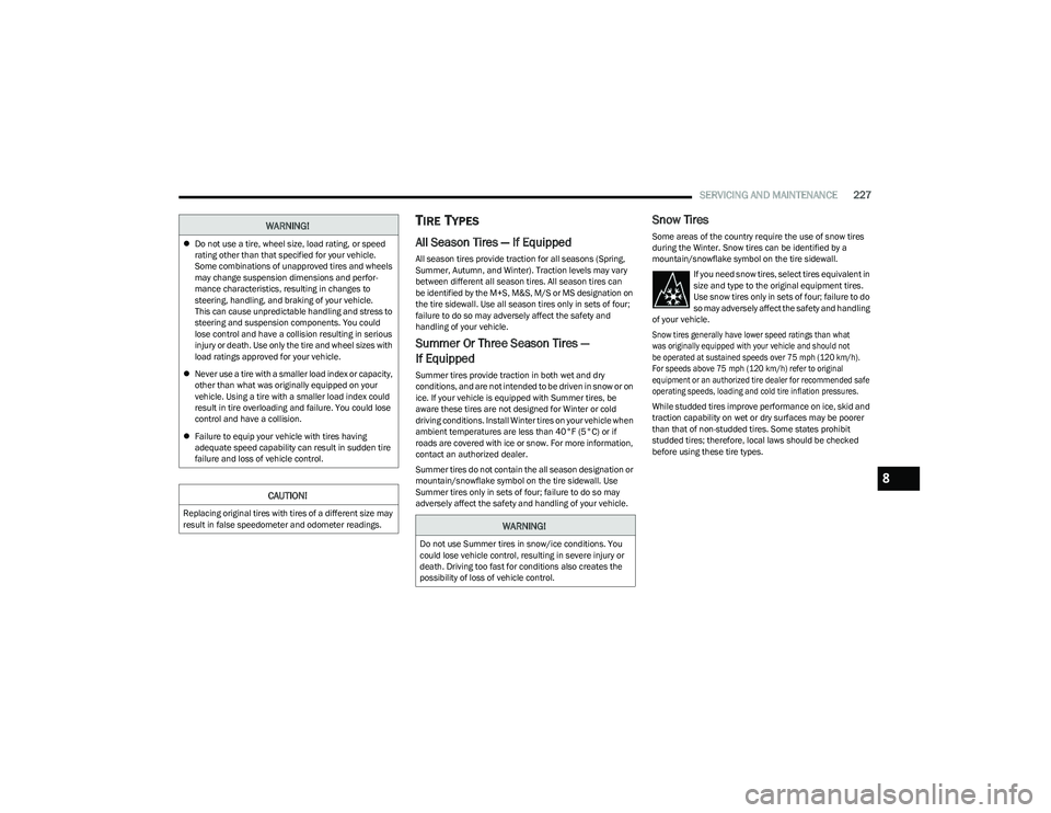
during the Winter. Snow tires can be identified by a
mountain/snowflake symbol on the tire sidewall.
If you need snow tires, select tires equivalent in
size and type to the original equipment tires.
Use snow tires only in sets of four; failure to do
so may adversely affect the safety and handling
of your vehicle.
Snow tires generally have lower speed ratings than what
was originally equipped with your vehicle and should not
be operated at sustained speeds over 75 mph (120 km/h).
For speeds above 75 mph (120 km/h) refer to original equipment or an authorized tire dealer for recommended safe
operating speeds, loading and cold tire inflation pressures.
While studded tires improve performance on ice, skid and
traction capability on wet or dry surfaces may be poorer
than that of non-studded tires. Some states prohibit
studded tires; therefore, local laws should be checked
before using these tire types.WARNING!
Do not use a tire, wheel size, load rating, or speed
rating other than that specified for your vehicle.
Some combinations of unapproved tires and wheels
may change suspension dimensions and perfor -
mance characteristics, resulting in changes to
steering, handling, and braking of your vehicle.
This can cause unpredictable handling and stress to
steering and suspension components. You could
lose control and have a collision resulting in serious
injury or death. Use only the tire and wheel sizes with
load ratings approved for your vehicle.
Never use a tire with a smaller load index or capacity,
other than what was originally equipped on your
vehicle. Using a tire with a smaller load index could
result in tire overloading and failure. You could lose
control and have a collision.
Failure to equip your vehicle with tires having
adequate speed capability can result in sudden tire
failure and loss of vehicle control.
CAUTION!
Replacing original tires with tires of a different size may
result in false speedometer and odometer readings.WARNING!
Do not use Summer tires in snow/ice conditions. You
could lose vehicle control, resulting in severe injury or
death. Driving too fast for conditions also creates the
possibility of loss of vehicle control.
8
23_RUV_OM_EN_US_t.book Page 227
Page 232 of 256
230SERVICING AND MAINTENANCE
(Continued)
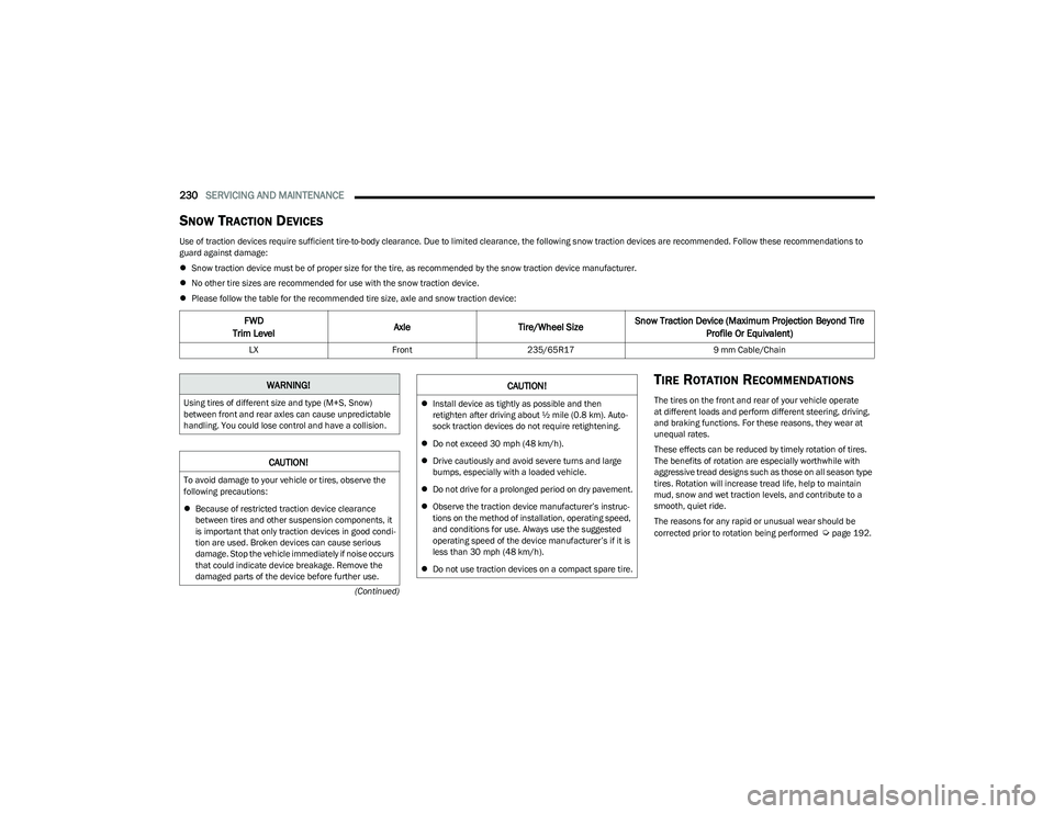
SNOW TRACTION DEVICES
Use of traction devices require sufficient tire-to-body clearance. Due to limited clearance, the following snow traction devices are recommended. Follow these recommendations to
guard against damage:
Snow traction device must be of proper size for the tire, as recommended by the snow traction device manufacturer.
No other tire sizes are recommended for use with the snow traction device.
Please follow the table for the recommended tire size, axle and snow traction device:
TIRE ROTATION RECOMMENDATIONS
The tires on the front and rear of your vehicle operate
at different loads and perform different steering, driving,
and braking functions. For these reasons, they wear at
unequal rates.
These effects can be reduced by timely rotation of tires.
The benefits of rotation are especially worthwhile with
aggressive tread designs such as those on all season type
tires. Rotation will increase tread life, help to maintain
mud, snow and wet traction levels, and contribute to a
smooth, quiet ride.
The reasons for any rapid or unusual wear should be
corrected prior to rotation being performed
Úpage 192.
FWD
Trim Level Axle
Tire/Wheel SizeSnow Traction Device (Maximum Projection Beyond Tire
Profile Or Equivalent)
LX Front235/65R17 9 mm Cable/Chain
WARNING!
Using tires of different size and type (M+S, Snow)
between front and rear axles can cause unpredictable
handling. You could lose control and have a collision.
CAUTION!
To avoid damage to your vehicle or tires, observe the
following precautions:
Because of restricted traction device clearance
between tires and other suspension components, it
is important that only traction devices in good condi -
tion are used. Broken devices can cause serious
damage. Stop the vehicle immediately if noise occurs
that could indicate device breakage. Remove the
damaged parts of the device before further use.
Install device as tightly as possible and then
retighten after driving about ½ mile (0.8 km). Auto -
sock traction devices do not require retightening.
Do not exceed 30 mph (48 km/h).
Drive cautiously and avoid severe turns and large
bumps, especially with a loaded vehicle.
Do not drive for a prolonged period on dry pavement.
Observe the traction device manufacturer’s instruc -
tions on the method of installation, operating speed,
and conditions for use. Always use the suggested
operating speed of the device manufacturer’s if it is
less than 30 mph (48 km/h).
Do not use traction devices on a compact spare tire.
CAUTION!
23_RUV_OM_EN_US_t.book Page 230