tow Citroen C ZERO 2014.5 1.G User Guide
[x] Cancel search | Manufacturer: CITROEN, Model Year: 2014.5, Model line: C ZERO, Model: Citroen C ZERO 2014.5 1.GPages: 176, PDF Size: 5.22 MB
Page 82 of 176
80
The incorrect installation of a child seat in a
vehicle compromises the child's protection
in the event of an accident.
Check that there is no seat belt or seat belt
buckle under the child seat as this could
destabilise it.
Remember to fasten the seat belts or the
child seat harnesses keeping the slack in
relation to the child's body to a minimum,
even for short journeys.
When installing a child seat using the seat
belt, check that the seat belt is tightened
correctly on the child seat and that it
secures the child seat firmly on the seat
of your vehicle. If your passenger seat is
adjustable, move it for ward if necessary.
at t
he rear seats, always leave sufficient
space between the front seat and:
-
a r
ear ward facing child seat,
-
t
he feet of a child seated in a for ward
facing child seat.
For this, move the front seat for ward and if
necessary straighten its backrest.
Advice on child seats
Children at the front
The legislation on carrying a child on the
front passenger seat is specific to each
c o unt r y.
Refer to the legislation in force in
your
country.
Deactivate the passenger's airbag when
a rear ward facing child seat is installed on
the front seat.
Other wise, the child would risk being
seriously injured or killed if the airbag were
deployed. For optimum installation of a for ward facing
child seat, ensure that the back of the
child seat is as close as possible to the
backrest of the vehicle's seat, or in contact
if possible.
The head restraint must be removed before
installing a child seat with a backrest on
the passenger seat. Ensure that the head
restraint is stowed or attached securely so
that it is not thrown around the vehicle in
the event of sharp braking.
Refit the head restraint as soon as the child
seat is removed.
Installing a booster seat
The chest part of the seat belt must be
positioned on the child's shoulder without
touching the neck.
Ensure that the lap part of the seat belt
passes correctly over the child's thighs.
CITROËN recommends the use of a
booster seat which has a back, fitted with a
seat belt guide at shoulder level.
As a safety precaution, do not leave:
-
o
ne or more children alone and
unsupervised in a vehicle,
-
a c
hild or an animal in a vehicle which
is exposed to the sun, with the windows
closed,
-
t
he keys within reach of children inside
the vehicle.
To prevent accidental opening of the doors,
use the "Child lock".
Take care not to open the rear windows by
more than one third.
To protect young children from the rays of
the sun, fit side blinds on the rear windows.
Child safety
Page 85 of 176
83
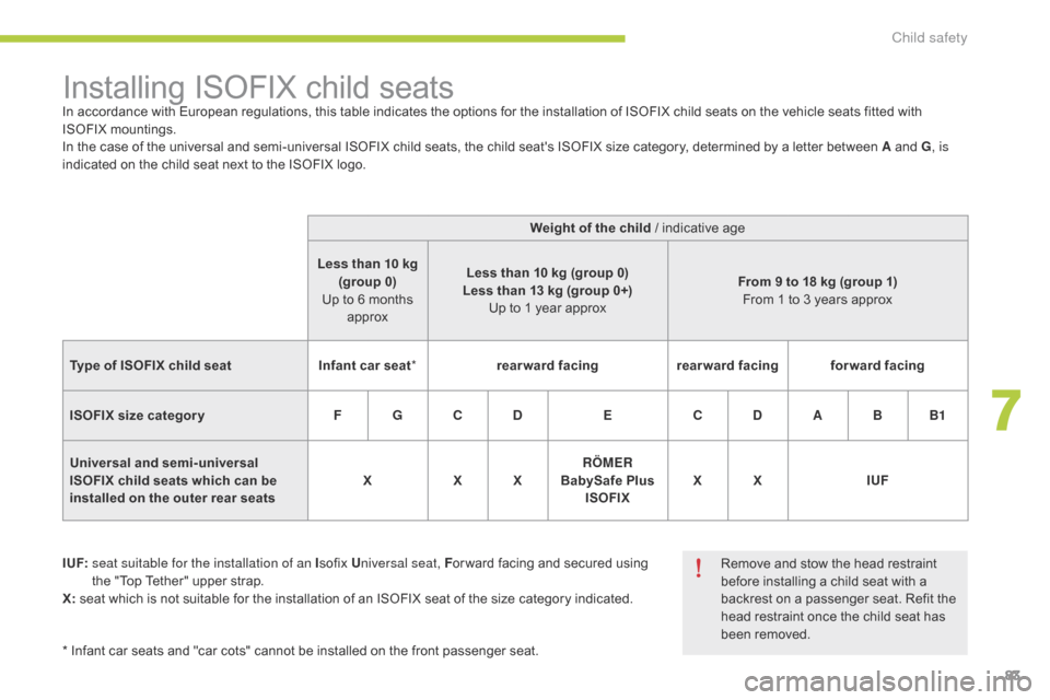
Installing ISOFIX child seatsIn accordance with European regulations, this table indicates the options for the installation of ISOFIX child seats on the vehicle seats fitted with
ISOFIX mountings.
In the case of the universal and semi-universal ISOFIX child seats, the child seat's ISOFIX size category, determined by a letter between A and G, is
indicated on the child seat next to the ISOFIX logo.
I UF:
s
eat suitable for the installation of an I sofix Universal seat, F or ward facing and secured using
the "Top Tether" upper strap.
X: seat which is not suitable for the installation of an ISOFIX seat of the size category indicated. Weight of the child / indicative age
Less than 10 kg (group 0)
Up to 6 months approx Less than 10 kg (group 0)
Less than 13 kg (group 0+) Up to 1 year approx From 9 to 18 kg (group 1)
From 1 to 3 years approx
Type of ISOFIX child seat Infant car seat*rearward facing rearward facingforward facing
ISOFIX size categor y F G C D EC D A B B1
Universal and semi-universal
ISOFIX child seats which can be
installed on the outer rear seats X
X X RÖMER
BabySafe Plus ISOFIX X X
IUF
* Infant car seats and "car cots" cannot be installed on the front passenger seat. Remove and stow the head restraint
before installing a child seat with a
backrest on a passenger seat. Refit the
head restraint once the child seat has
been removed.
7
Child safety
Page 90 of 176
88
As a safety measure, the motor will
not start when the charging cable is
connected to the vehicle's socket.
Also, any attempt to start the motor
interrupts the charging procedure. It will
then be necessary to disconnect and
reconnect the charging cable plug to
continue charging.After charging, close the charging
socket cover and flap.
Take care to avoid the ingress of water
or dust to the socket and its cover
or the charging plug (risk of fire or
electrocution).
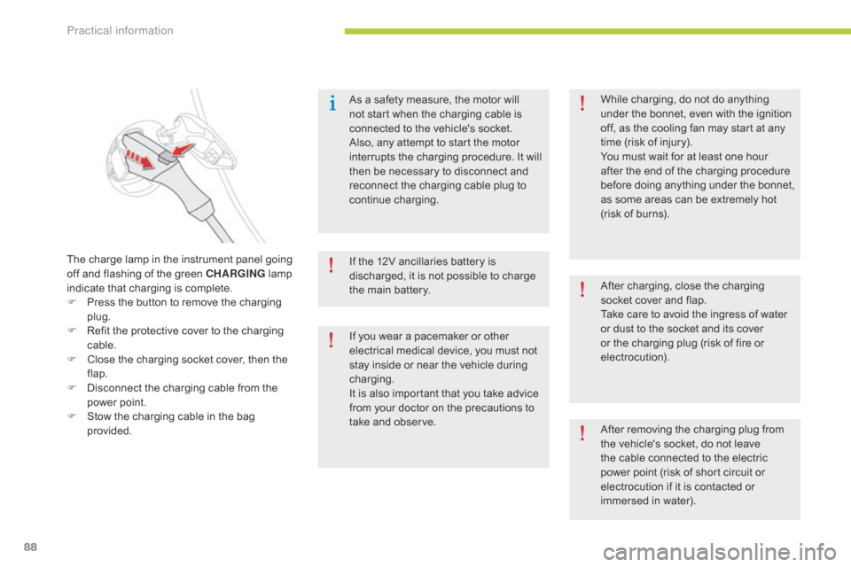
The charge lamp in the instrument panel going
off and flashing of the green CHARGING
lamp
indicate that charging is complete.
F
P
ress the button to remove the charging
plug.
F
R
efit the protective cover to the charging
cable.
F
C
lose the charging socket cover, then the
flap.
F
D
isconnect the charging cable from the
power point.
F
S
tow the charging cable in the bag
provided. If the 12V ancillaries battery is
discharged, it is not possible to charge
the main battery.
If you wear a pacemaker or other
electrical medical device, you must not
stay inside or near the vehicle during
charging.
It is also important that you take advice
from your doctor on the precautions to
take and observe.While charging, do not do anything
under the bonnet, even with the ignition
off, as the cooling fan may start at any
time (risk of injury).
You must wait for at least one hour
after the end of the charging procedure
before doing anything under the bonnet,
as some areas can be extremely hot
(risk of burns).
After removing the charging plug from
the vehicle's socket, do not leave
the cable connected to the electric
power point (risk of short circuit or
electrocution if it is contacted or
immersed in water).
Practical information
Page 102 of 176
100
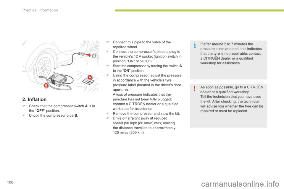
2. Inflation
F Check that the compressor switch A is in the " OFF" position.
F
U
ncoil the compressor pipe B .F
C
onnect this pipe to the valve of the
repaired wheel.
F
C
onnect the compressor's electric plug to
the vehicle's 12 V socket (ignition switch in
position "ON" or "ACC").
F
S
tart the compressor by turning the switch A
to the " ON" position.
F
U
sing the compressor, adjust the pressure
in accordance with the vehicle's tyre
pressure label (located in the driver's door
aperture).
A l
oss of pressure indicates that the
puncture has not been fully plugged;
contact a CITROËN dealer or a qualified
workshop for assistance.
F
R
emove the compressor and stow the kit.
F
D
rive off straight away at reduced
speed (50
mph [80 km/h] max) limiting
the distance travelled to approximately
120
miles (200 km).As soon as possible, go to a CITROËN
dealer or a qualified workshop.
Tell the technician that you have used
the kit. After checking, the technician
will advise you whether the tyre can be
repaired or must be replaced. If after around 5 to 7 minutes the
pressure is not attained, this indicates
that the tyre is not repairable; contact
a CITROËN dealer or a qualified
workshop for assistance.
Practical information
Page 108 of 176
106
Changing a bulb
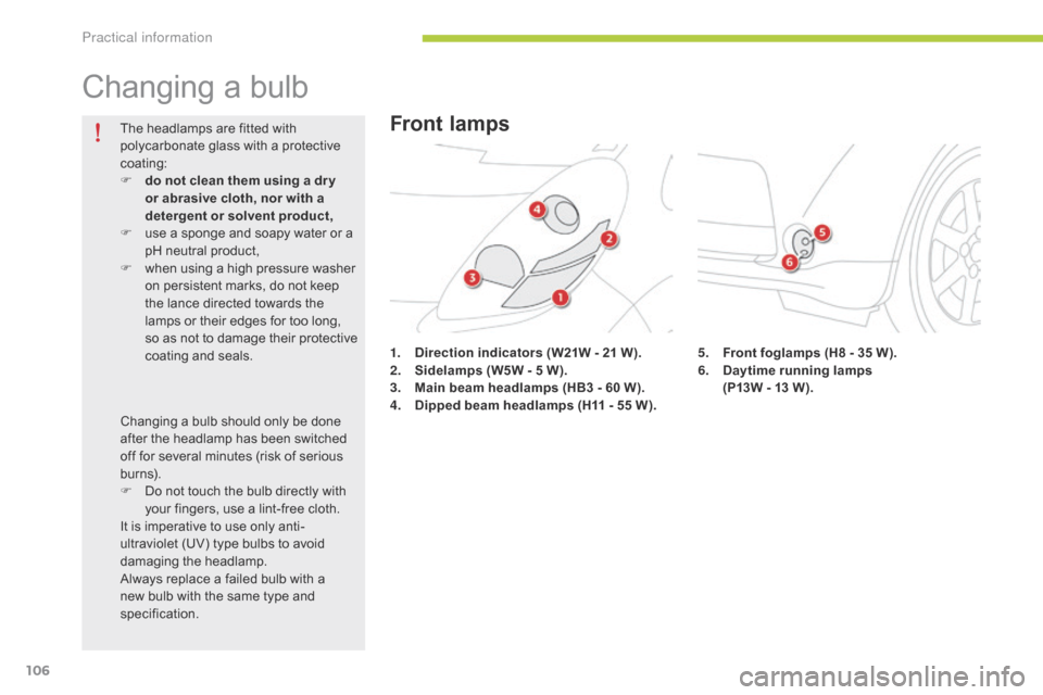
1. Direction indicators (W21W - 21 W).
2. S idelamps (W5W - 5 W).
3.
M
ain beam headlamps (HB3 - 60 W).
4.
D
ipped beam headlamps (H11 - 55 W) .
The headlamps are fitted with
polycarbonate glass with a protective
coating:
F
d
o not clean them using a dr y
or abrasive cloth, nor with a
detergent or solvent product,
F
u
se a sponge and soapy water or a
pH neutral product,
F
w
hen using a high pressure washer
on persistent marks, do not keep
the lance directed towards the
lamps or their edges for too long,
so as not to damage their protective
coating and seals.
Changing a bulb should only be done
after the headlamp has been switched
off for several minutes (risk of serious
burns).
F
D
o not touch the bulb directly with
your fingers, use a lint-free cloth.
It is imperative to use only anti-
ultraviolet (UV) type bulbs to avoid
damaging the headlamp.
Always replace a failed bulb with a
new bulb with the same type and
specification.
Front lamps
5. Front foglamps (H8 - 35 W).
6. D aytime running lamps
(P13W - 13 W).
Practical information
Page 110 of 176

108
F Slacken fixing screw D, while holding the
bumper away.
F
S
lacken fixing screw E . F
P ull the lamp towards you, and disengage
the tab F to remove it completely.
Practical information
Page 113 of 176
111
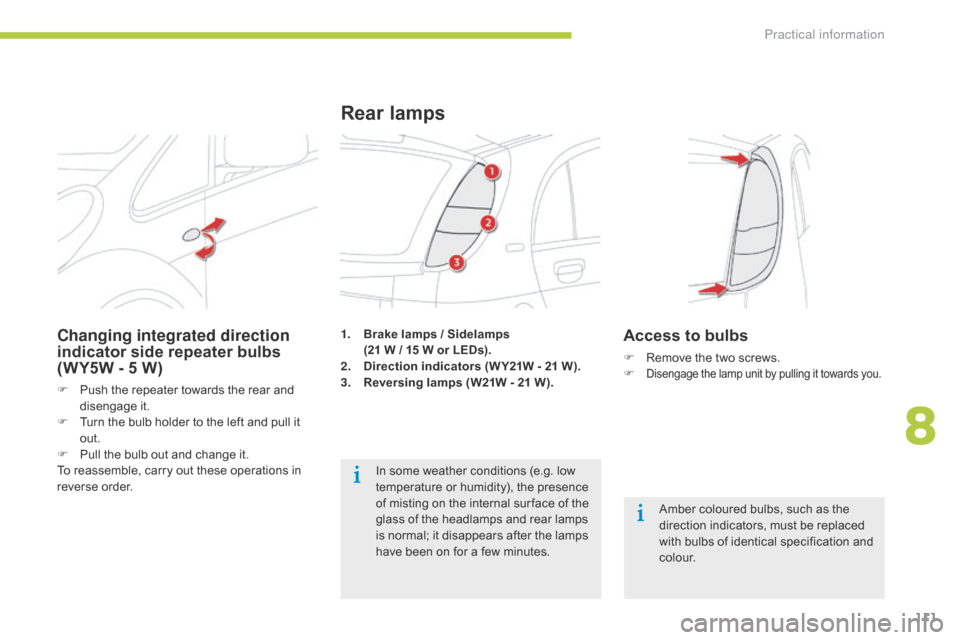
1. Brake lamps / Sidelamps
(21 W / 15 W or LEDs).
2.
D
irection indicators (W Y21W - 21 W).
3.
R
eversing lamps (W21W - 21 W).
Rear lamps
Amber coloured bulbs, such as the
direction indicators, must be replaced
with bulbs of identical specification and
c o l o u r.
In some weather conditions (e.g. low
temperature or humidity), the presence
of misting on the internal sur face of the
glass of the headlamps and rear lamps
is normal; it disappears after the lamps
have been on for a few minutes.
Changing integrated direction
indicator side repeater bulbs
(WY5W - 5
W)
F Push the repeater towards the rear and disengage it.
F
T
urn the bulb holder to the left and pull it
out.
F
P
ull the bulb out and change it.
To reassemble, carry out these operations in
reverse order.
Access to bulbs
F Remove the two screws.
F Disengage the lamp unit by pulling it towards you.
8
Practical information
Page 116 of 176
114
Changing a fuse
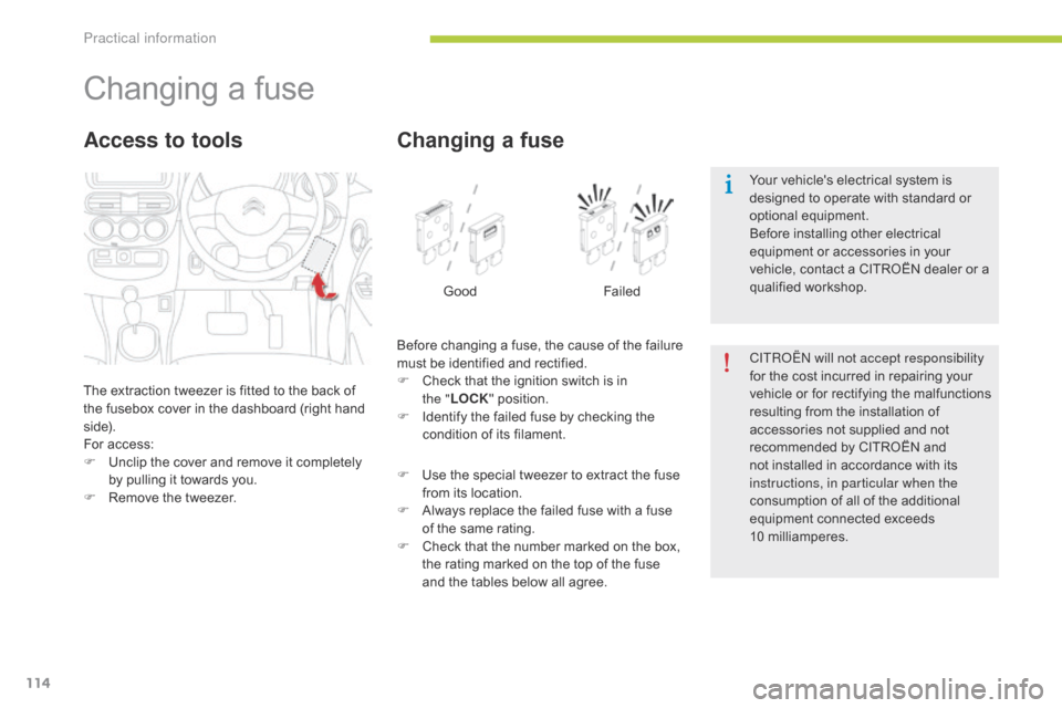
The extraction tweezer is fitted to the back of
the fusebox cover in the dashboard (right hand
side).
For access:
F
U
nclip the cover and remove it completely
by pulling it towards you.
F
R
emove the tweezer.
Access to tools
Before changing a fuse, the cause of the failure
must be identified and rectified.
F
C
heck that the ignition switch is in
the
"LOCK " position.
F
I
dentify the failed fuse by checking the
condition of its filament.
Changing a fuse
Good Failed
F
U
se the special tweezer to extract the fuse
from its location.
F
A
lways replace the failed fuse with a fuse
of the same rating.
F
C
heck that the number marked on the box,
the rating marked on the top of the fuse
and the tables below all agree. CITR
oËn
will not accept responsibility
for the cost incurred in repairing your
vehicle or for rectifying the malfunctions
resulting from the installation of
accessories not supplied and not
recommended by CITROËN and
not installed in accordance with its
instructions, in particular when the
consumption of all of the additional
equipment connected exceeds
10
mil
liamperes.
Your vehicle's electrical system is
designed to operate with standard or
optional equipment.
Before installing other electrical
equipment or accessories in your
vehicle, contact a CITROËN dealer or a
qualified workshop.
Practical information
Page 120 of 176
118
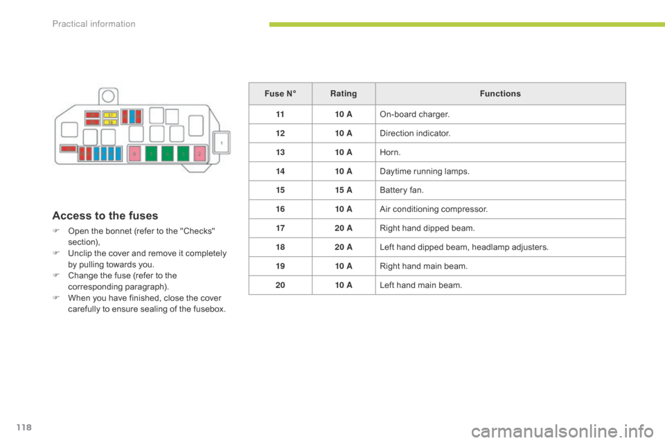
Access to the fuses
F Open the bonnet (refer to the "Checks" section),
F
U
nclip the cover and remove it completely
by pulling towards you.
F
C
hange the fuse (refer to the
corresponding paragraph).
F
W
hen you have finished, close the cover
carefully to ensure sealing of the fusebox. Fuse N°
Rating Functions
11 10 AOn-board charger.
12 10 ADirection indicator.
13 10 AHorn.
14 10 ADaytime running lamps.
15 15 ABattery fan.
16 10 AAir conditioning compressor.
17 20 ARight hand dipped beam.
18 20 ALeft hand dipped beam, headlamp adjusters.
19 10 ARight hand main beam.
20 10 ALeft hand main beam.
Practical information
Page 121 of 176
119
Towing the vehicleProcedure for having your vehicle towed using fixed mechanical equipment.
Towing your vehicle
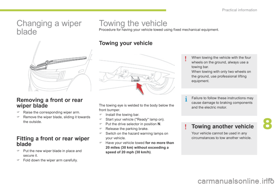
The towing eye is welded to the body below the
front bumper.
F
I
nstall the towing bar.
F
S
tart your vehicle ("Ready" lamp on).
F
P
ut the drive selector in position N .
F
R
elease the parking brake.
F
S
witch on the hazard warning lamps on
your vehicle.
F
H
ave your vehicle towed for no more than
20 miles (30 km) without exceeding a
speed of 20 mph (30 km/h) .When towing the vehicle with the four
wheels on the ground, always use a
towing bar.
When towing with only two wheels on
the ground, use professional lifting
equipment.
Failure to follow these instructions may
cause damage to braking components
and the electric motor.
Changing a wiper
blade
Removing a front or rear
wiper blade
F Raise the corresponding wiper arm.
F
R emove the wiper blade, sliding it towards
the outside.
Fitting a front or rear wiper
blade
F Put the new wiper blade in place and secure it.
F
F
old down the wiper arm carefully.
Towing another vehicle
Your vehicle cannot be used in any
circumstances to tow another vehicle.
8
Practical information