Citroen C ZERO 2015 1.G Owner's Manual
Manufacturer: CITROEN, Model Year: 2015, Model line: C ZERO, Model: Citroen C ZERO 2015 1.GPages: 176, PDF Size: 5.21 MB
Page 101 of 176

99
C-zero_en_Chap08_info-pratiques_ed01-2014
Repair procedure
1. Sealing
F Switch off the ignition.
F In dicate on the speed restriction sticker
provided, the wheel to be repaired, then fix
it to the steering wheel as a reminder that a
wheel is in temporary use.
F
Sh
ake the sealant cartridge, remove the
cap and screw on the injection pipe. F
Re
move the valve cap for the tyre to be
repaired.
F Re move the valve core using the tool
provided, and store in in a clean place.
F
Co
nnect the injection pipe to the valve of
the tyre to be repaired. F
Ta
p the sealant cartridge (top down)
several times with your hand, so as to
inject all of the product into the tyre.
F
Re
move the injection pipe.
F
Re
fit the valve core and tighten it using the
tool provided.
Take care, this product is harmful (e.g. ethylene-glycol, colophony...) if swallowed and
causes irritation to the eyes.
Keep it out of reach of children.
The use-by date of the sealant is marked on the cartridge.
After use, do not discard the empty cartridge but take it to a CITROËN dealer (France) or an
authorised waste disposal site.
Don't forget to obtain a replacement cartridge; they are available from a CITROËN dealer or
a qualified workshop.
Avoid removing any foreign bodies
which have penetrated into the tyre.
8
Practical information
Page 102 of 176

100
C-zero_en_Chap08_info-pratiques_ed01-2014
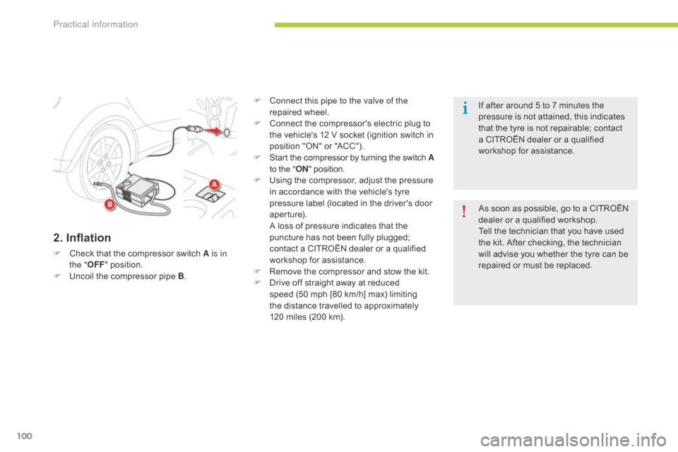
2. Inflation
F Check that the compressor switch A is in
the "OFF " position.
F
Un
coil the compressor pipe B .F
Co
nnect this pipe to the valve of the
repaired wheel.
F
Co
nnect the compressor's electric plug to
the vehicle's 12
V s
ocket (ignition switch in
position "ON" or "ACC").
F
St
art the compressor by turning the switch A
to the " ON" position.
F
Us
ing the compressor, adjust the pressure
in accordance with the vehicle's tyre
pressure label (located in the driver's door
aperture).
A lo
ss of pressure indicates that the
puncture has not been fully plugged;
contact a CITROËN dealer or a qualified
workshop for assistance.
F
Re
move the compressor and stow the kit.
F
Dr
ive off straight away at reduced
speed (50
m
ph [80
k
m/h] max) limiting
the distance travelled to approximately
120
m
iles (200
k
m).As soon as possible, go to a CITROËN
dealer or a qualified workshop.
Tell the technician that you have used
the kit. After checking, the technician
will advise you whether the tyre can be
repaired or must be replaced. If after around 5 to 7 minutes the
pressure is not attained, this indicates
that the tyre is not repairable; contact
a CITROËN dealer or a qualified
workshop for assistance.
Practical information
Page 103 of 176

101
C-zero_en_Chap08_info-pratiques_ed01-2014
Changing a wheel
Tools required
- A jack: for lifting the vehicle.
- A wh eelbrace: for removing and refitting
the wheel bolts.
-
A ha
ndle: for operating the jack.
These tools are not supplied with your vehicle.Parking the vehicle
Immobilise the vehicle where it does not
block traffic: the ground must be level,
stable and not slippery.
Apply the parking brake, switch off the
ignition and put the drive selector in
position P to lock the wheels.
If necessary, place a chock under the
wheel diagonally opposite the wheel to
be changed.
You must ensure that the occupants get
out of the vehicle and wait where they
are safe.
Never go underneath a vehicle raised
using a jack; use an axle stand.
Wheel with wheel trim
When removing the wheel , first
remove the wheel trim using the
wheelbrace, by pulling at the valve hole.
When fitting the wheel , refit the wheel
trim starting by aligning the valve hole
with the valve, and then press on the
edge of the trim with the palm of your
hand.
8
Practical information
Page 104 of 176

102
C-zero_en_Chap08_info-pratiques_ed01-2014
F Extend the jack until its head comes into contact with the jacking point A or B used. The
vehicle's contact sur face A or B must be engaged with the central part of the head of the jack.
F
Ra
ise the vehicle until there is sufficient space between the wheel and the ground.
F Sl
acken the bolts using the wheelbrace.
F Po
sition the foot of the jack on the ground
and ensure that it is directly below the
front
A
or rear B jacking point provided on
the underbody, whichever is closest to the
wheel to be changed.
Removing a wheel
Practical information
Page 105 of 176

103
C-zero_en_Chap08_info-pratiques_ed01-2014
F Remove the bolts and store them in a clean
place.
F
Re
move the wheel. Ensure that the jack is stable. If the
ground is slippery or loose, the jack
might slip or drop - Risk of injury!
Take care to position the jack only at
one of the vehicle’s jacking points A
or B under the vehicle, ensuring that the
contact sur face of the vehicle’s jacking
point is centred on the head of the jack.
Other wise there is a risk of damage to
the vehicle and/or that the jack might
drop - Risk of injury!
8
Practical information
Page 106 of 176

104
C-zero_en_Chap08_info-pratiques_ed01-2014
Fitting a wheel
F Put the wheel in place on the hub.
F Sc rew in the bolts by hand.
F
Pr
e-tighten the bolts using the wheelbrace. F Lo
wer the vehicle fully.
F Fo ld the jack and detach it.F Ti
ghten the bolts using the wheelbrace.
After changing a wheel
Have the tightness of the bolts and the
tyre pressure of the new wheel checked
by a CITROËN dealer or a qualified
workshop without delay.
Practical information
Page 107 of 176

105
C-zero_en_Chap08_info-pratiques_ed01-2014
Snow chains
The snow chains must be fitted only to the rear wheels (vehicle with rear wheel drive).It is strongly recommended that before
you leave, you practise fitting the snow
chains on a level and dry sur face. Take account of the legislation in force
in your country on the use of snow
chains and the maximum running speed
authorised. For more information on snow chains,
contact a CITROËN dealer or a
qualified workshop.Avoid driving with snow chains on roads
that have been cleared of snow, to
avoid damaging your vehicle's tyres and
the road sur face. If your vehicle is fitted
with alloy wheels, check that no part of
the chain or its fixings is in contact with
the wheel rim.Advice on installation
F If you have to fit the chains during a
j
ourney, stop the vehicle on a flat sur face
on the side of the road.
F
Ap
ply the parking brake and position any
wheel chocks to prevent movement of your
vehicle.
F
Fi
t the chains following the instructions
provided by the manufacturer.
F
Mov
e off gently and drive for a few
moments, without exceeding 30 mph
(50 km/h).
F
St
op your vehicle and check that the snow
chains are correctly tightened.
Use only the chains designed to be fitted to the
type of wheel fitted to your vehicle:
Original
tyre size Maximum link
size.
175/55 R15 9 mm
145/65 R15
cannot be fitted with chains
8
Practical information
Page 108 of 176

106
C-zero_en_Chap08_info-pratiques_ed01-2014
Changing a bulb
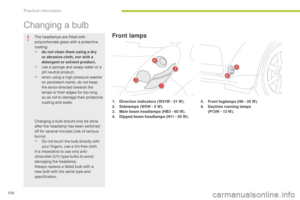
1. Direction indicators (W21W - 21 W).
2. Si delamps (W5W - 5 W).
3.
Ma
in beam headlamps (HB3 - 60 W).
4.
Di
pped beam headlamps (H11 - 55 W).
The headlamps are fitted with
polycarbonate glass with a protective
coating:
F
do n
ot clean them using a dr y
or abrasive cloth, nor with a
detergent or solvent product,
F
us
e a sponge and soapy water or a
pH neutral product,
F
wh
en using a high pressure washer
on persistent marks, do not keep
the lance directed towards the
lamps or their edges for too long,
so as not to damage their protective
coating and seals.
Changing a bulb should only be done
after the headlamp has been switched
off for several minutes (risk of serious
burns).
F
Do n
ot touch the bulb directly with
your fingers, use a lint-free cloth.
It is imperative to use only anti-
ultraviolet (UV) type bulbs to avoid
damaging the headlamp.
Always replace a failed bulb with a
new bulb with the same type and
specification.
Front lamps
5. Front foglamps (H8 - 35 W).
6. Da ytime running lamps
(P13W - 13 W).
Practical information
Page 109 of 176

107
C-zero_en_Chap08_info-pratiques_ed01-2014
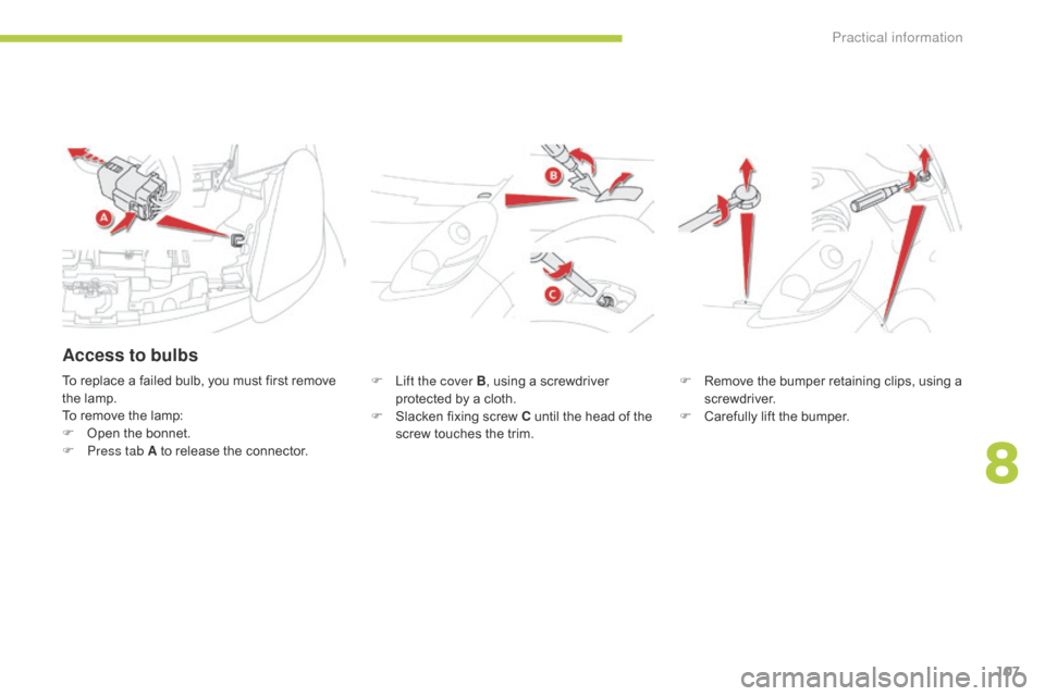
F Lift the cover B, u sing a screwdriver
protected by a cloth.
F
Sl
acken fixing screw C until the head of the
screw touches the trim. F Re
move the bumper retaining clips, using a
screwdriver.
F
Ca
refully lift the bumper.
To replace a failed bulb, you must first remove
the lamp.
To remove the lamp:
F
Op
en the bonnet.
F
Pr
ess tab A to release the connector.
Access to bulbs
8
Practical information
Page 110 of 176

108
C-zero_en_Chap08_info-pratiques_ed01-2014
F Slacken fixing screw D, w hile holding the
bumper away.
F
Sl
acken fixing screw E . F Pu
ll the lamp towards you, and disengage
the tab F to remove it completely.
Practical information