cable Citroen C4 2005 2.G Workshop Manual
[x] Cancel search | Manufacturer: CITROEN, Model Year: 2005, Model line: C4, Model: Citroen C4 2005 2.GPages: 462, PDF Size: 10.48 MB
Page 3 of 462
Downloaded from www.Manualslib.com manuals search engine PRESENTATION
THIS HANDBOOKsummarises the specifications, adjustments, checks and special features of CITROËN private vehicles, not including UTILITY vehicles for which there exists a separate
handbook.
The handbook is divided into groups representing the main functions:
GENERAL - ENGINE - INJECTION - IGNITION - CLUTCH, GEARBOX, DRIVESHAFTS - AXLES, SUSPENSION, STEERING - BRAKES - AIR CONDITIONING.
In each section, the vehicles are dealt with in the following order: C4 - XSARA - XSARA PICASSO - BERLINGO and all models where applicable.
The information given in this handbook is based on vehicles marketed in EUROPE.
Angl-t2-Index-2005 9/01/06 10:05 Page I
Page 238 of 462
![Citroen C4 2005 2.G Workshop Manual Downloaded from www.Manualslib.com manuals search engine 232
ENGINECHECKING AND SETTING THE VALVE TIMING
Engines: 8HX - 8HZ
B1BP2LXC
Tools.
[1] Pliers for removing plastic pegs: 7504-T
[2]Lever for de Citroen C4 2005 2.G Workshop Manual Downloaded from www.Manualslib.com manuals search engine 232
ENGINECHECKING AND SETTING THE VALVE TIMING
Engines: 8HX - 8HZ
B1BP2LXC
Tools.
[1] Pliers for removing plastic pegs: 7504-T
[2]Lever for de](/img/9/4138/w960_4138-237.png)
Downloaded from www.Manualslib.com manuals search engine 232
ENGINECHECKING AND SETTING THE VALVE TIMING
Engines: 8HX - 8HZ
B1BP2LXC
Tools.
[1] Pliers for removing plastic pegs: 7504-T
[2]Lever for detensioning the dynamic tensioner roller: (-).0194.E
[3]Engine flywheel setting peg: (-).0194.C
[4] Camshaft setting peg: (-).0194.B
[5]Crankshaft and high pressure pump setting peg: (-).0194.A
Preliminary operations.
Remove:
- The front RH wheel.
- The front RH splash-shield, using tool [1].
- The clips of the electrical harness on the upper timing cover.
- The accessories belt, using tool [2]
(see corresponding operation).
Checking the setting.
Disconnect the battery negative cable.
Remove the upper timing cover (1).
Rotate the engine using the screw (2)of the crankshaft pulley.
NOTE:The locking hole is located under the crankshaft bearing cap cover.
Undo the screw (2).
Detension the auxiliary drive belt dynamic tensioner roller, using tool [2].
XSARA
Angl.-t2-page135-239-2005 9/01/06 10:14 Page 232
Page 337 of 462
Downloaded from www.Manualslib.com manuals search engine 331
CLUTCH
GEARBOX
TRANSMISSION
MA/5 GEARBOX CONTROLS
Engines: KFU - NFU
B2CP3ZCD
Gear controls
C4
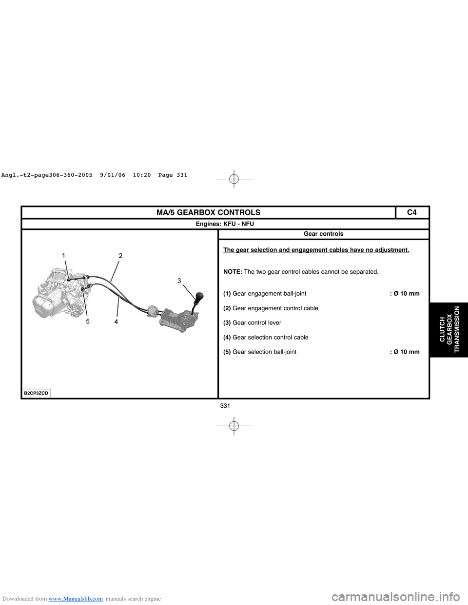
The gear selection and engagement cables have no adjustment.
NOTE:The two gear control cables cannot be separated.
(1)Gear engagement ball-joint: Ø 10 mm
(2)Gear engagement control cable
(3)Gear control lever
(4)Gear selection control cable
(5)Gear selection ball-joint: Ø 10 mm
Angl.-t2-page306-360-2005 9/01/06 10:20 Page 331
Page 338 of 462
Downloaded from www.Manualslib.com manuals search engine 332
CLUTCH
GEARBOX
TRANSMISSION
MA/5 GEARBOX CONTROLS
Engines: KFU - NFU
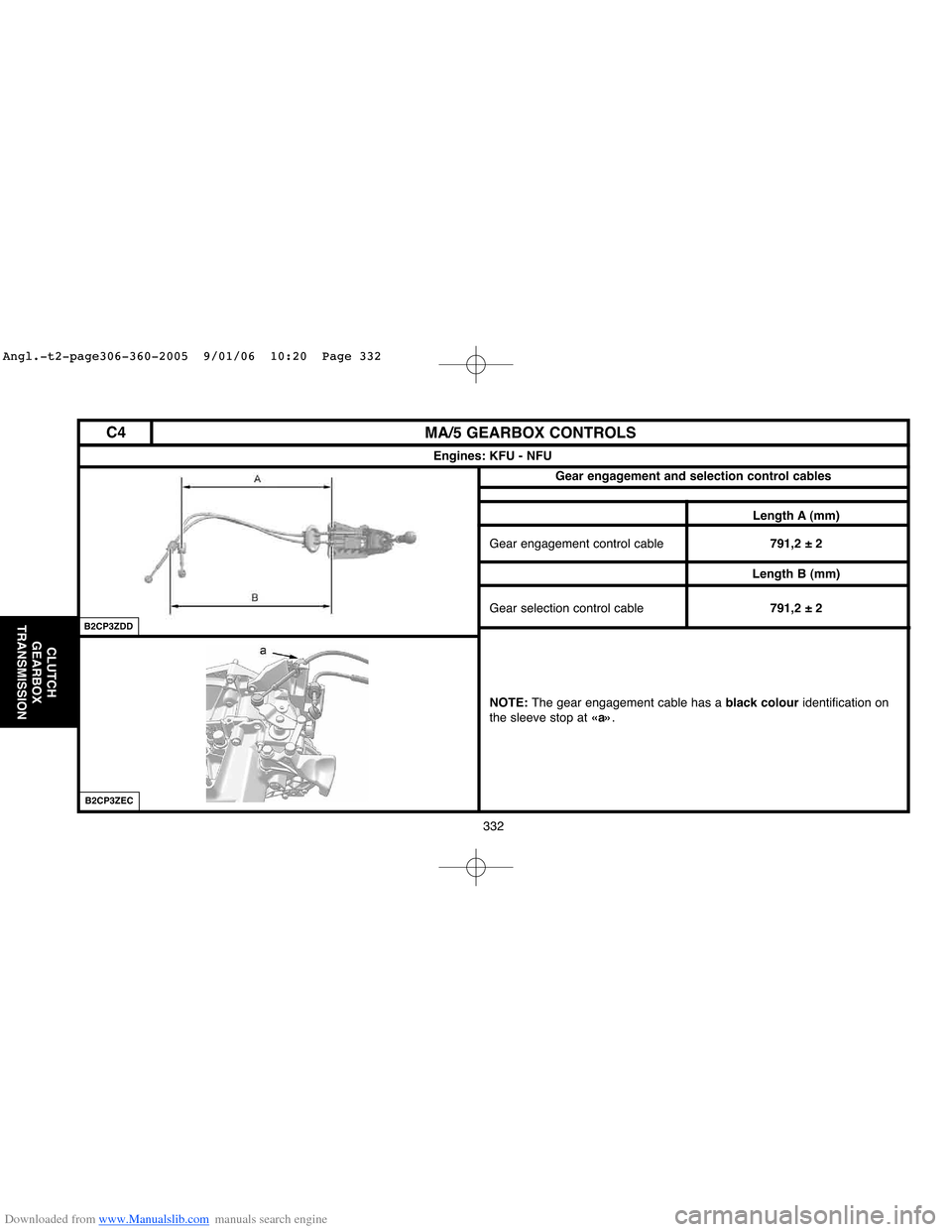
Length A (mm)
Gear engagement control cable791,2 ± 2
Length B (mm)
Gear selection control cable791,2 ± 2
NOTE: The gear engagement cable has a black colouridentification on
the sleeve stop at«a».
Gear engagement and selection control cables
B2CP3ZDD
B2CP3ZEC
C4
Angl.-t2-page306-360-2005 9/01/06 10:20 Page 332
Page 341 of 462
Downloaded from www.Manualslib.com manuals search engine 335
CLUTCH
GEARBOX
TRANSMISSION
BE4/5 GEARBOX CONTROLS
Engines: NFU - RFN - RFK - 9HX - 9HY - 9HZ
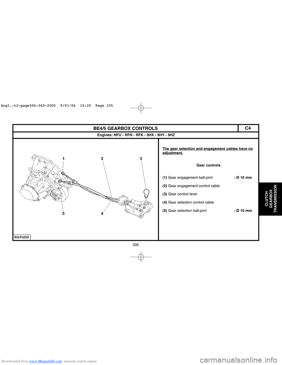
The gear selection and engagement cables have noadjustment.
Gear controls.
(1)Gear engagement ball-joint: Ø 10 mm
(2)Gear engagement control cable
(3)Gear control lever
(4)Gear selection control cable
(5)Gear selection ball-joint: Ø 10 mm
B2CP3ZOD
C4
Angl.-t2-page306-360-2005 9/01/06 10:20 Page 335
Page 342 of 462

Downloaded from www.Manualslib.com manuals search engine 336
CLUTCH
GEARBOX
TRANSMISSION
BE4/5 GEARBOX CONTROLS
Engines: NFU - RFN - RFK - 9HX - 9HY - 9HZ
Length A (mm)
Gear engagement control cable643 ± 2
Length B (mm)
Gear selection control cable670 ± 2
NOTE:The gear engagement cable has a black colouridentification
on the sleeve stop at «a».
B2CP3Z1CB2CP3Z2C
C4
Angl.-t2-page306-360-2005 9/01/06 10:20 Page 336
Page 344 of 462
Downloaded from www.Manualslib.com manuals search engine 338
CLUTCH
GEARBOX
TRANSMISSION
BE4/5 GEARBOX CONTROLS
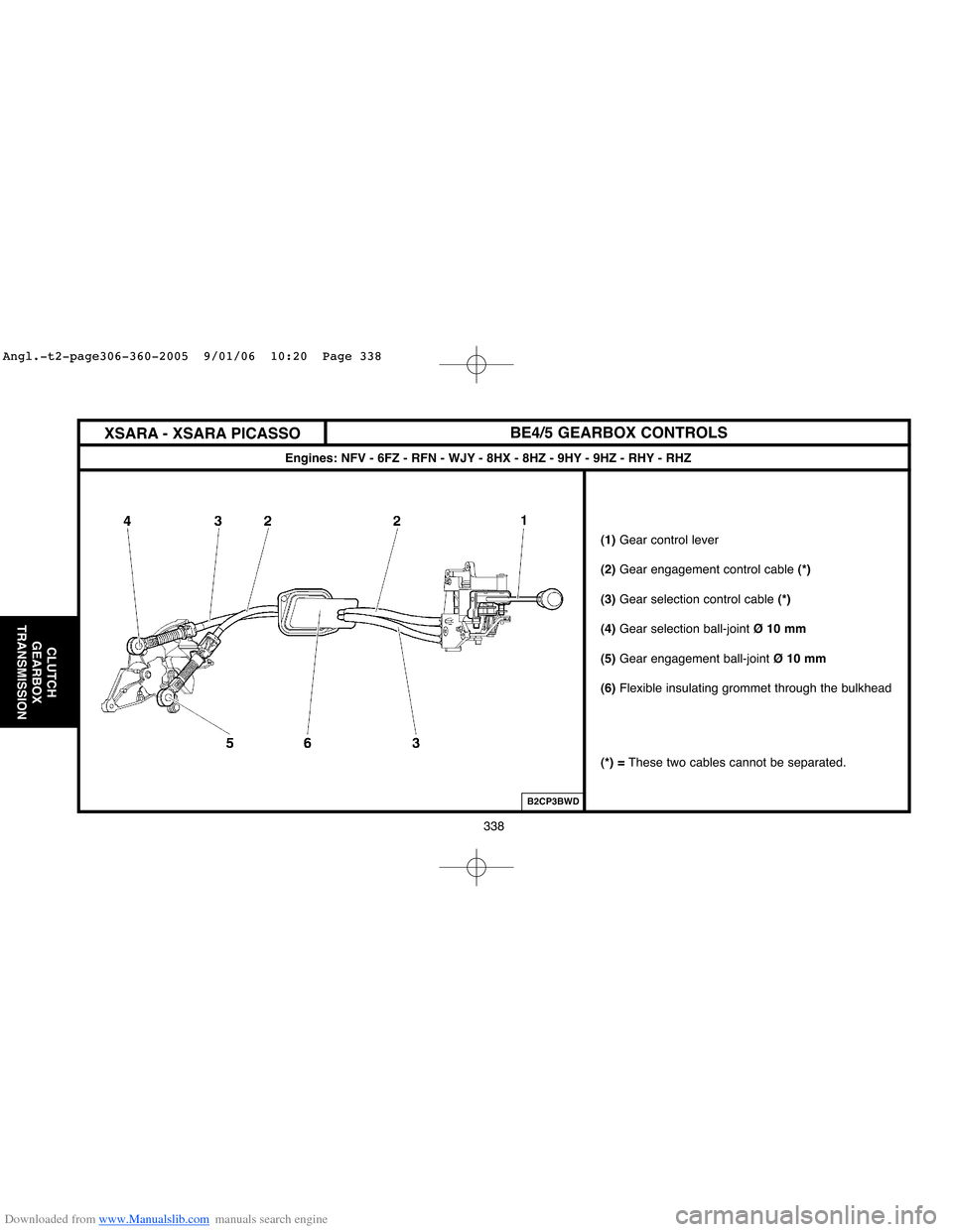
Engines: NFV - 6FZ - RFN - WJY - 8HX - 8HZ - 9HY - 9HZ - RHY - RHZ
(1)Gear control lever
(2)Gear engagement control cable (*)
(3) Gear selection control cable (*)
(4)Gear selection ball-joint Ø 10 mm
(5)Gear engagement ball-jointØ 10 mm
(6)Flexible insulating grommet through the bulkhead
(*) = These two cables cannot be separated.
B2CP3BWD
XSARA - XSARA PICASSO
Angl.-t2-page306-360-2005 9/01/06 10:20 Page 338
Page 345 of 462
Downloaded from www.Manualslib.com manuals search engine 339
CLUTCH
GEARBOX
TRANSMISSION
CHECKS AND ADJUSTMENTS: BE4/5 GEARBOX CONTROLS
Principles of adjusting the gear controls.
WARNING: Cables should be adjusted each time the gearbox, gear controls or power unit are
removed.
Principles.
Lock the gear lever in neutral position, using tool: 9607-T.
Place the gearbox in neutral.
Couple the cables on the lever.
Fit the ball-joints on the gearbox lever.
Lock the cable lengths with the ball-joint locking keys.
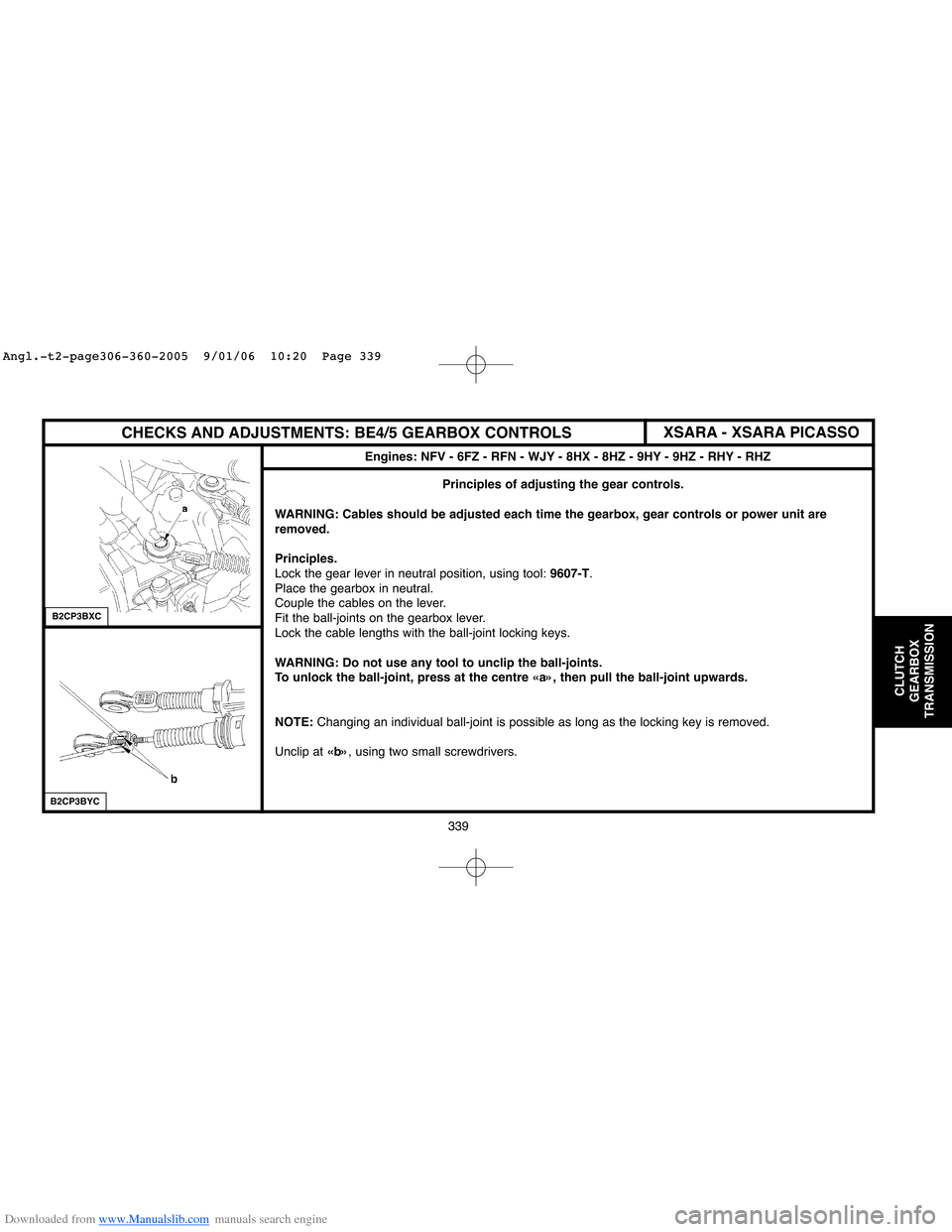
WARNING: Do not use any tool to unclip the ball-joints.
To unlock the ball-joint, press at the centre «a», then pull the ball-joint upwards.
NOTE:Changing an individual ball-joint is possible as long as the locking key is removed.
Unclip at «b», using two small screwdrivers.
Engines: NFV - 6FZ - RFN - WJY - 8HX - 8HZ - 9HY - 9HZ - RHY - RHZ
XSARA - XSARA PICASSO
B2CP3BXC
B2CP3BYC
Angl.-t2-page306-360-2005 9/01/06 10:20 Page 339
Page 346 of 462
![Citroen C4 2005 2.G Workshop Manual Downloaded from www.Manualslib.com manuals search engine 340
CLUTCH
GEARBOX
TRANSMISSION
CHECKS AND ADJUSTMENTS: BE4/5 GEARBOX CONTROLS
Tools.
[1]Tool for positioning the gear lever: 9607-T
Adjustment Citroen C4 2005 2.G Workshop Manual Downloaded from www.Manualslib.com manuals search engine 340
CLUTCH
GEARBOX
TRANSMISSION
CHECKS AND ADJUSTMENTS: BE4/5 GEARBOX CONTROLS
Tools.
[1]Tool for positioning the gear lever: 9607-T
Adjustment](/img/9/4138/w960_4138-345.png)
Downloaded from www.Manualslib.com manuals search engine 340
CLUTCH
GEARBOX
TRANSMISSION
CHECKS AND ADJUSTMENTS: BE4/5 GEARBOX CONTROLS
Tools.
[1]Tool for positioning the gear lever: 9607-T
Adjustments.
WARNING: Cables should be adjusted each time
the gearbox, gear controls or power unit are
removed.
Inside the vehicle.
Remove the trim under the gear lever.
Lock the gear lever in neutral position, using tool [1].
Under the bonnet.
Remove the air filter assembly.
Unlock the ball-joint keys at «a».
Place the gear selection and control levers on neutral.
Lock the cable lengths with the ball-joint locking keys.Checks.
Remove the tool [1].
Check that all the gears engage without «tightness».
Check that the gear lever moves identically forwards
and backwards and to right and left.
If it does not, repeat the adjustment.
Refit the trim under the gear lever.
Refit the air filter assembly.
Adjusting the gear controls Engines: NFV - 6FZ - RFN - WJY - 8HX - 8HZ - 9HZ - 9HY - RHY - RHZ
XSARA - XSARA PICASSO
B2CP3C6CB2CP3C0C
Angl.-t2-page306-360-2005 9/01/06 10:20 Page 340
Page 347 of 462
Downloaded from www.Manualslib.com manuals search engine 341
CLUTCH
GEARBOX
TRANSMISSION
ML6 GEARBOX CONTROLS
Engine: RHR
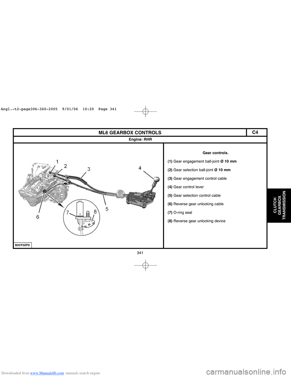
Gear controls.
(1)Gear engagement ball-joint Ø 10 mm
(2)Gear selection ball-joint Ø 10 mm
(3)Gear engagement control cable
(4)Gear control lever
(5)Gear selection control cable
(6)Reverse gear unlocking cable
(7)O-ring seal
(8)Reverse gear unlocking device
B2CP3ZPD
C4
Angl.-t2-page306-360-2005 9/01/06 10:20 Page 341