pipe Citroen C4 2005 2.G Workshop Manual
[x] Cancel search | Manufacturer: CITROEN, Model Year: 2005, Model line: C4, Model: Citroen C4 2005 2.GPages: 462, PDF Size: 10.48 MB
Page 112 of 462
Downloaded from www.Manualslib.com manuals search engine 106
ENGINESPECIAL FEATURES - TIGHTENING TORQUES (m.daN)
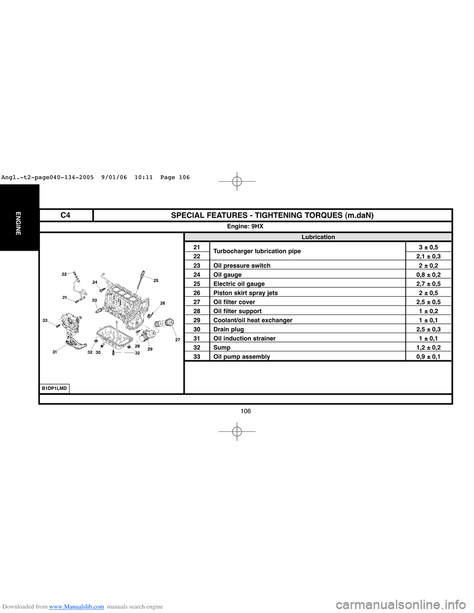
Lubrication
21
Turbocharger lubrication pipe3 ± 0,5
222,1 ± 0,3
23 Oil pressure switch 2 ± 0,2
24 Oil gauge 0,8 ± 0,2
25 Electric oil gauge 2,7 ± 0,5
26 Piston skirt spray jets 2 ± 0,5
27 Oil filter cover 2,5 ± 0,5
28 Oil filter support 1 ± 0,2
29 Coolant/oil heat exchanger 1 ± 0,1
30 Drain plug 2,5 ± 0,3
31 Oil induction strainer 1 ± 0,1
32 Sump 1,2 ± 0,2
33 Oil pump assembly 0,9 ± 0,1
Engine: 9HX
B1DP1LMD
C4
Angl.-t2-page040-134-2005 9/01/06 10:11 Page 106
Page 124 of 462
Downloaded from www.Manualslib.com manuals search engine 118
ENGINE
118
SPECIAL FEATURES - TIGHTENING TORQUES (m.daN)
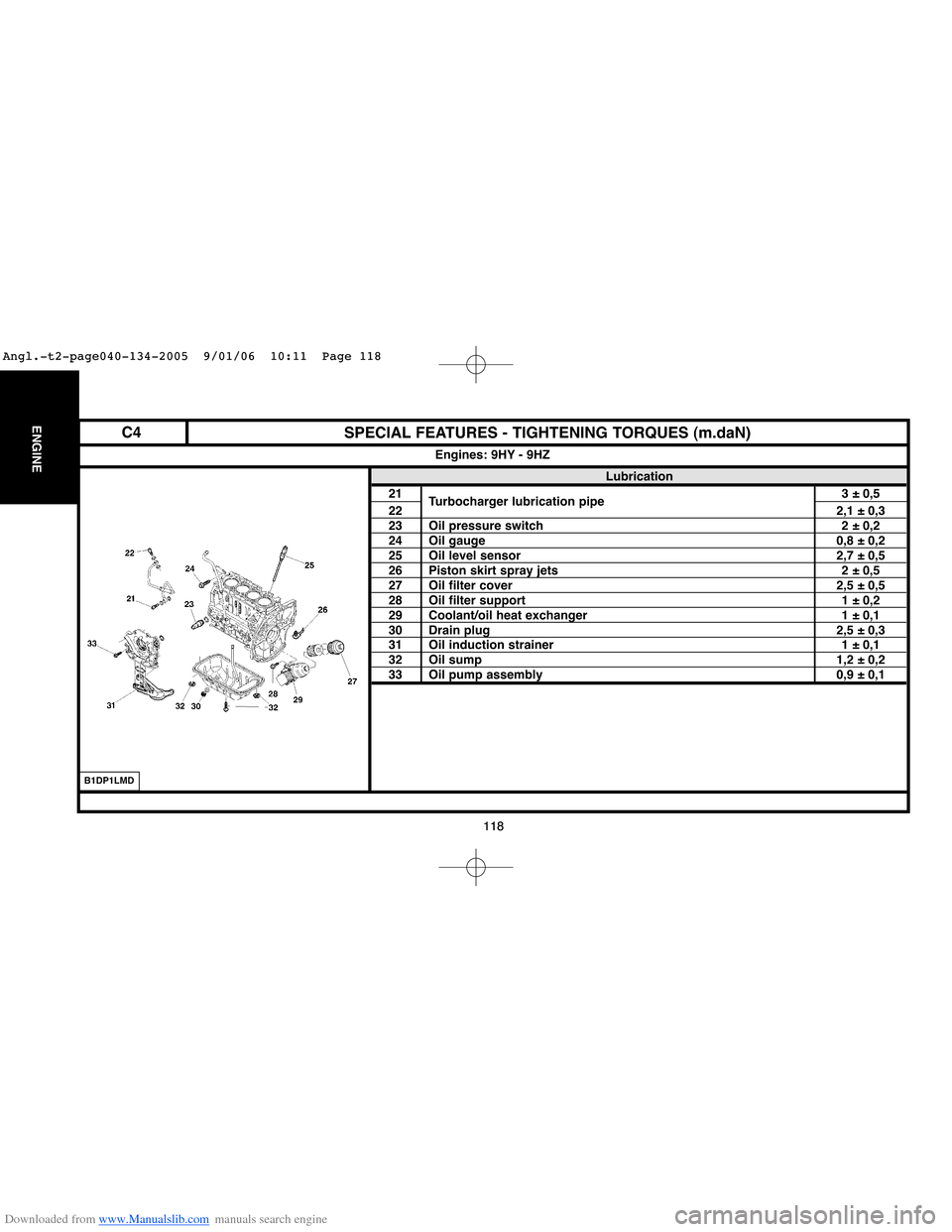
Lubrication
21
Turbocharger lubrication pipe3 ± 0,5
222,1 ± 0,323 Oil pressure switch 2 ± 0,224 Oil gauge 0,8 ± 0,225 Oil level sensor 2,7 ± 0,526 Piston skirt spray jets 2 ± 0,527 Oil filter cover 2,5 ± 0,528 Oil filter support 1 ± 0,229 Coolant/oil heat exchanger 1 ± 0,130 Drain plug 2,5 ± 0,331 Oil induction strainer 1 ± 0,132 Oil sump 1,2 ± 0,233 Oil pump assembly 0,9 ± 0,1
Engines: 9HY - 9HZ
B1DP1LMD
C4
Angl.-t2-page040-134-2005 9/01/06 10:11 Page 118
Page 134 of 462
Downloaded from www.Manualslib.com manuals search engine 128
ENGINESPECIAL FEATURES - TIGHTENING TORQUES (m.daN)
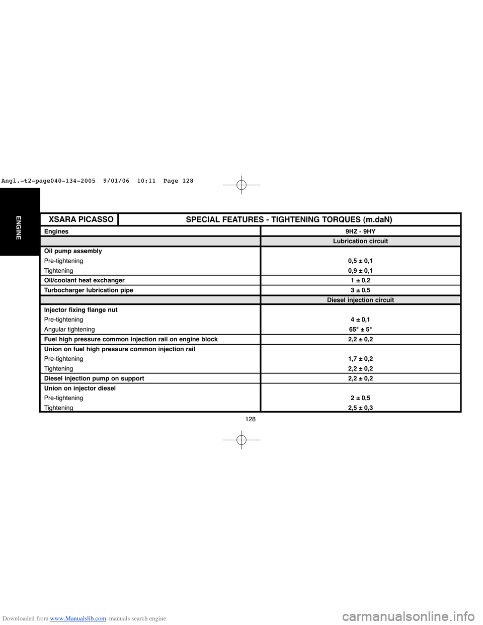
Engines9HZ - 9HY
Lubrication circuit
Oil pump assembly
Pre-tightening0,5 ± 0,1
Tightening0,9 ± 0,1
Oil/coolant heat exchanger1 ± 0,2
Turbocharger lubrication pipe3 ± 0,5
Diesel injection circuit
Injector fixing flange nut
Pre-tightening4 ± 0,1
Angular tightening65°±5°
Fuel high pressure common injection rail on engine block 2,2 ± 0,2
Union on fuel high pressure common injection rail
Pre-tightening1,7 ± 0,2
Tightening2,2 ± 0,2
Diesel injection pump on support2,2 ± 0,2
Union on injector diesel
Pre-tightening2 ± 0,5
Tightening2,5 ± 0,3
XSARA PICASSO
Angl.-t2-page040-134-2005 9/01/06 10:11 Page 128
Page 142 of 462
Downloaded from www.Manualslib.com manuals search engine 136
ENGINESPECIAL FEATURES - TIGHTENING TORQUES (m.daN)
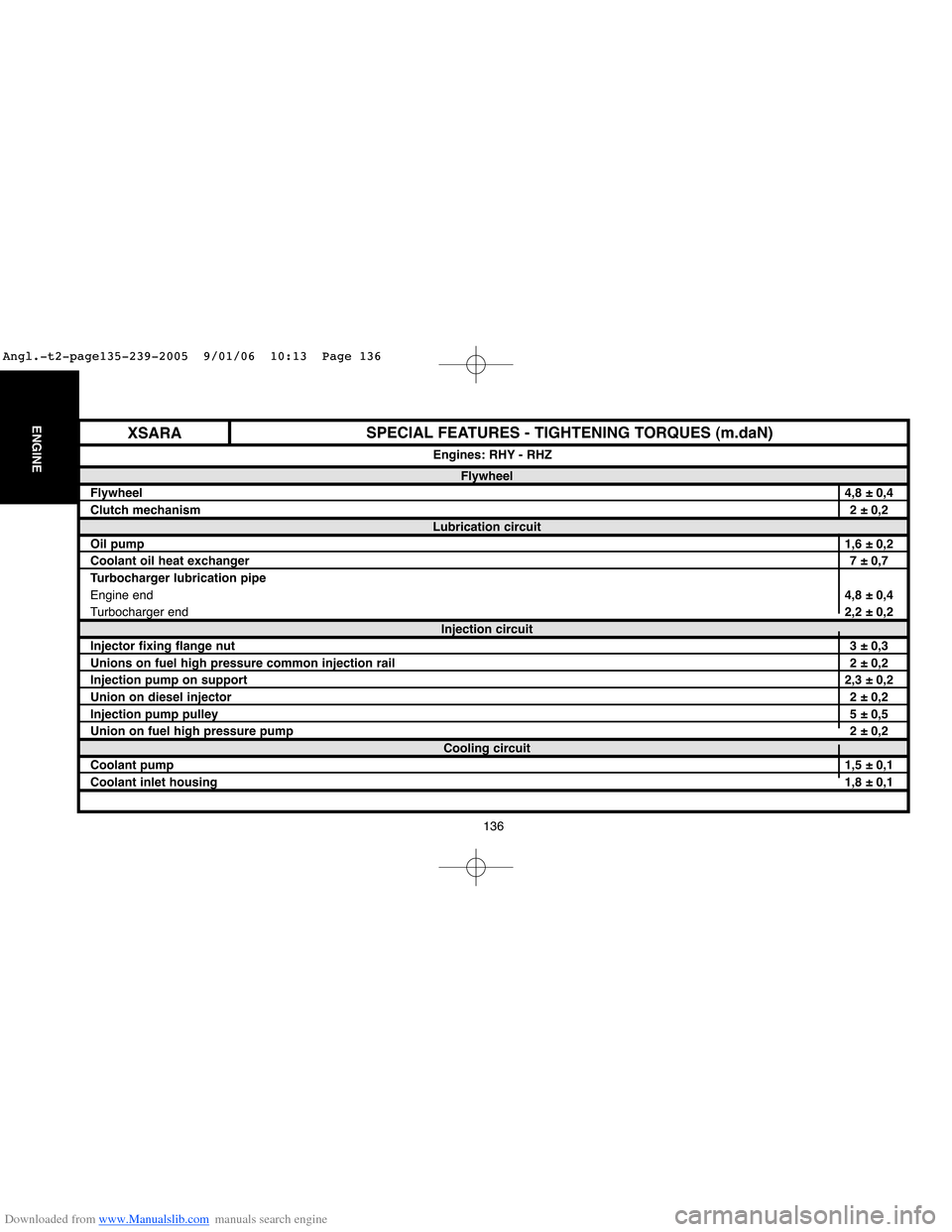
Flywheel
Flywheel4,8 ± 0,4
Clutch mechanism2 ± 0,2
Lubrication circuit
Oil pump1,6 ± 0,2
Coolant oil heat exchanger7 ± 0,7
Turbocharger lubrication pipe
Engine end4,8 ± 0,4
Turbocharger end2,2 ± 0,2
Injection circuit
Injector fixing flange nut3 ± 0,3
Unions on fuel high pressure common injection rail2 ± 0,2
Injection pump on support2,3 ± 0,2
Union on diesel injector2 ± 0,2
Injection pump pulley5 ± 0,5
Union on fuel high pressure pump2 ± 0,2
Cooling circuit
Coolant pump1,5 ± 0,1
Coolant inlet housing1,8 ± 0,1 Engines: RHY - RHZ
XSARA
Angl.-t2-page135-239-2005 9/01/06 10:13 Page 136
Page 152 of 462
Downloaded from www.Manualslib.com manuals search engine 146
ENGINESPECIAL FEATURES - TIGHTENING TORQUES (m.daN)
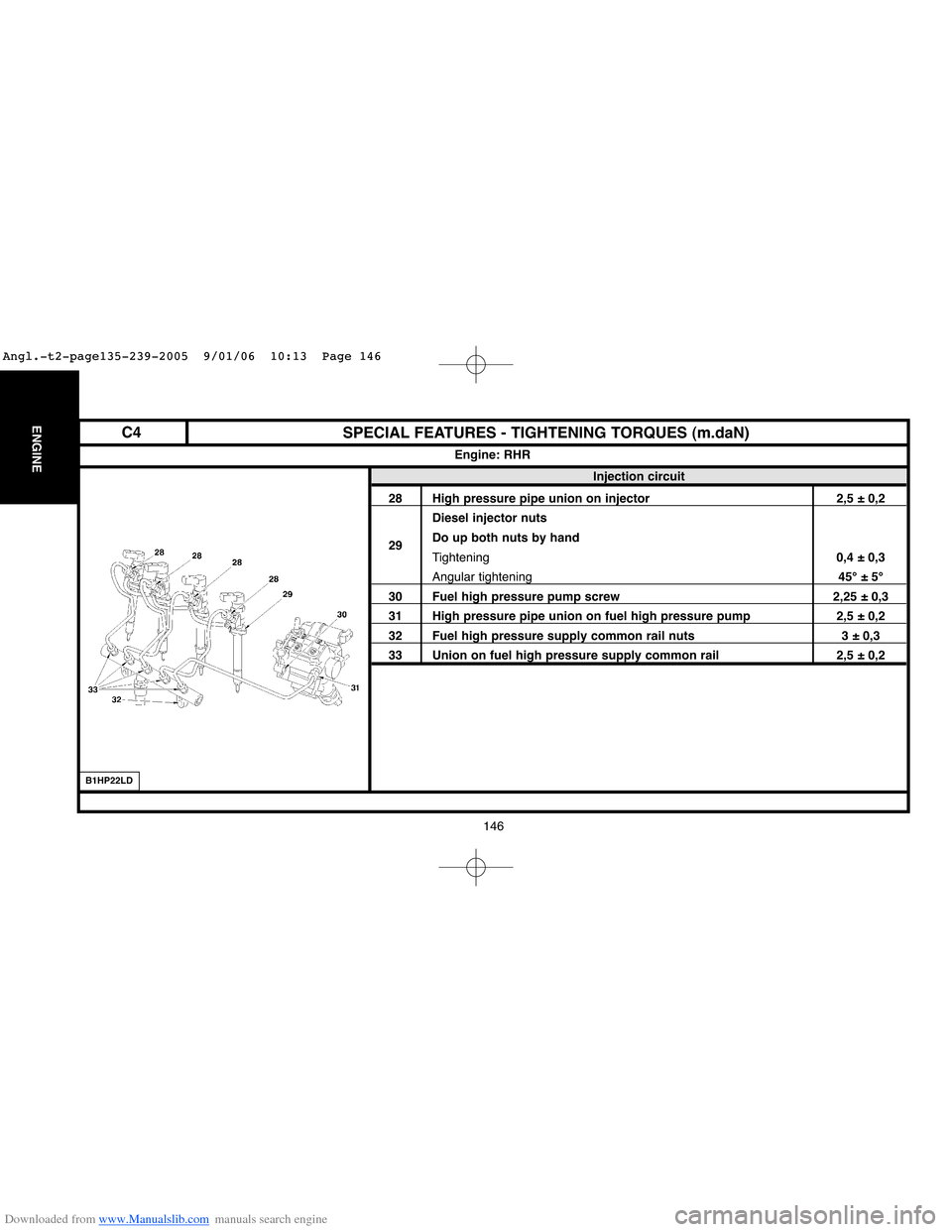
Injection circuit
28 High pressure pipe union on injector 2,5 ± 0,2
Diesel injector nuts
29Do up both nuts by hand
Tightening0,4 ± 0,3
Angular tightening45°±5°
30 Fuel high pressure pump screw 2,25 ± 0,3
31 High pressure pipe union on fuel high pressure pump 2,5 ± 0,2
32 Fuel high pressure supply common rail nuts 3 ± 0,3
33 Union on fuel high pressure supply common rail 2,5 ± 0,2
Engine: RHR
B1HP22LD
C4
Angl.-t2-page135-239-2005 9/01/06 10:13 Page 146
Page 212 of 462
Downloaded from www.Manualslib.com manuals search engine 206
ENGINECHECKING AND SETTING THE VALVE TIMING
Engine: RFJ
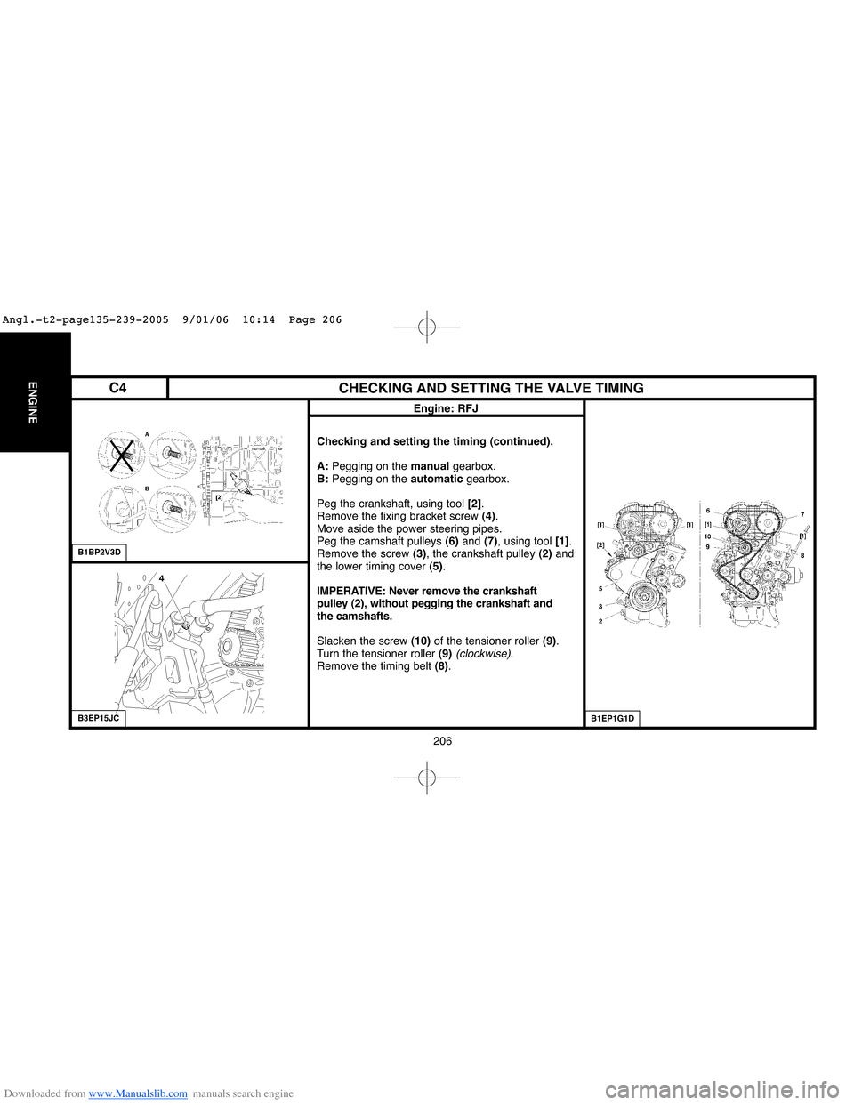
Checking and setting the timing (continued).
A:Pegging on the manual gearbox.
B:Pegging on the automaticgearbox.
Peg the crankshaft, using tool [2].
Remove the fixing bracket screw (4).
Move aside the power steering pipes.
Peg the camshaft pulleys (6)and (7), using tool [1].
Remove the screw (3), the crankshaft pulley (2)and
the lower timing cover (5).
IMPERATIVE: Never remove the crankshaft
pulley (2), without pegging the crankshaft and
the camshafts.
Slacken the screw (10)of the tensioner roller (9).
Turn the tensioner roller (9)
(clockwise).
Remove the timing belt (8).
B1BP2V3D
B1EP1G1DB3EP15JC
C4
Angl.-t2-page135-239-2005 9/01/06 10:14 Page 206
Page 219 of 462
Downloaded from www.Manualslib.com manuals search engine 213
ENGINE
213
CHECKING AND SETTING THE VALVE TIMING
Engine: RFN
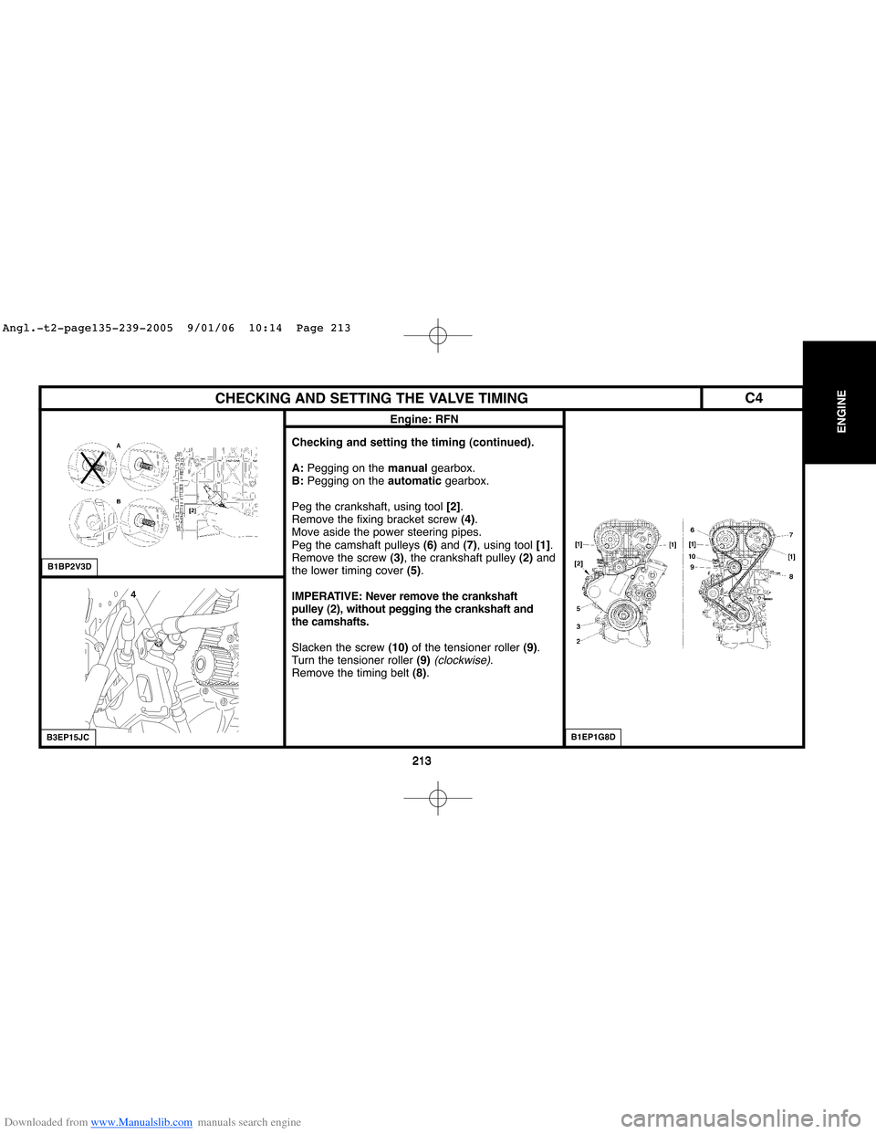
Checking and setting the timing (continued).
A:Pegging on the manualgearbox.
B:Pegging on the automatic gearbox.
Peg the crankshaft, using tool [2].
Remove the fixing bracket screw (4).
Move aside the power steering pipes.
Peg the camshaft pulleys (6)and (7), using tool [1].
Remove the screw (3), the crankshaft pulley (2)and
the lower timing cover (5).
IMPERATIVE: Never remove the crankshaft
pulley (2), without pegging the crankshaft and
the camshafts.
Slacken the screw (10)of the tensioner roller (9).
Turn the tensioner roller (9)
(clockwise).
Remove the timing belt (8).
B1BP2V3D
B3EP15JCB1EP1G8D
C4
Angl.-t2-page135-239-2005 9/01/06 10:14 Page 213
Page 232 of 462
![Citroen C4 2005 2.G Workshop Manual Downloaded from www.Manualslib.com manuals search engine 226
ENGINECHECKING AND SETTING THE VALVE TIMING
Engine: RFK
Tools.
[1]Camshaft setting peg: (-).0189.A
[2]Crankshaft setting peg: (-).0189.R
[3 Citroen C4 2005 2.G Workshop Manual Downloaded from www.Manualslib.com manuals search engine 226
ENGINECHECKING AND SETTING THE VALVE TIMING
Engine: RFK
Tools.
[1]Camshaft setting peg: (-).0189.A
[2]Crankshaft setting peg: (-).0189.R
[3](/img/9/4138/w960_4138-231.png)
Downloaded from www.Manualslib.com manuals search engine 226
ENGINECHECKING AND SETTING THE VALVE TIMING
Engine: RFK
Tools.
[1]Camshaft setting peg: (-).0189.A
[2]Crankshaft setting peg: (-).0189.R
[3] Timing belt retaining pin: (-) 0189.K
[4]Adaptor for angular tightening: 4069-T
[5]Hub immobilising tool: (-).0189.S
[5a] : (-).0189.S1
[5b] : (-).0189.S2
Pliers for removing plastic pins: 7504-T
IMPERATIVE: Respect the safety and cleanliness requirements.
Checking and setting the timing.
Removing.
Disconnect the negative terminal of the battery
(see corresponding operation).
Raise and support the vehicle, front wheels hanging.
Remove the auxiliaries drive belt
(see corresponding operation).
Unclip and move aside the fuel supply hose from the timing cover.
Remove the screw (1).
Move aside the power steering pipes.
Turn the engine by means of the screw (4)of the crankshaft pinion (3)to bring it to the pegging position.
B3EP15YC
B1BP36YC
C4
Angl.-t2-page135-239-2005 9/01/06 10:14 Page 226
Page 240 of 462
Downloaded from www.Manualslib.com manuals search engine 234
ENGINECHECKING AND SETTING THE VALVE TIMING
Engines: 8HX - 8HZ
B1EP18GC
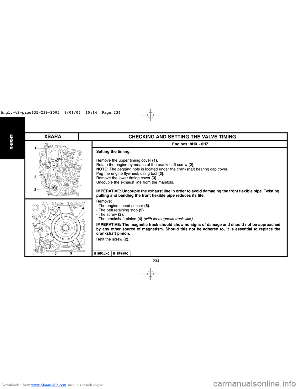
Setting the timing.
Remove the upper timing cover (1).
Rotate the engine by means of the crankshaft screw (2).
NOTE:The pegging hole is located under the crankshaft bearing cap cover.
Peg the engine flywheel, using tool [3].
Remove the lower timing cover (3).
Uncouple the exhaust line from the manifold.
IMPERATIVE: Uncouple the exhaust line in order to avoid damaging the front flexible pipe. Twisting,
pulling and bending the front flexible pipe reduces its life.
Remove:
- The engine speed sensor (6).
- The belt retaining stop (5).
- The screw (2).
- The crankshaft pinion (4)
(with its magnetic track «a»).
IMPERATIVE: The magnetic track should show no signs of damage and should not be approached
by any other source of magnetism. Should this not be adhered to, it is essential to replace the
crankshaft pinion.
Refit the screw (2).
B1BP2LXC
XSARA
Angl.-t2-page135-239-2005 9/01/06 10:14 Page 234
Page 246 of 462
![Citroen C4 2005 2.G Workshop Manual Downloaded from www.Manualslib.com manuals search engine 240
ENGINECHECKING THE VALVE TIMING
Engines: 9HX - 9HY - 9HZ
Tools.
[1]Flywheel setting peg: (-).0194.C
[2] Camshaft setting peg: (-).0194.B
[3 Citroen C4 2005 2.G Workshop Manual Downloaded from www.Manualslib.com manuals search engine 240
ENGINECHECKING THE VALVE TIMING
Engines: 9HX - 9HY - 9HZ
Tools.
[1]Flywheel setting peg: (-).0194.C
[2] Camshaft setting peg: (-).0194.B
[3](/img/9/4138/w960_4138-245.png)
Downloaded from www.Manualslib.com manuals search engine 240
ENGINECHECKING THE VALVE TIMING
Engines: 9HX - 9HY - 9HZ
Tools.
[1]Flywheel setting peg: (-).0194.C
[2] Camshaft setting peg: (-).0194.B
[3] Crankshaft setting peg: (-).0194.A
IMPERATIVE: Respect the safety and cleanliness requirements specific to High pressure Diesel
injection (HDi) engine versions.
Checking and setting the timing.
Raise and support the vehicle, wheels hanging.
Disconnect the battery.
Uncouple:
- The fuel supply unions (1).
- The air/air heat exchanger inlet and outlet pipes (3).
- The exhaust line at the catalytic converter flexible pipe.
- Disconnect the connecteur at «a».
Remove the accessories drive belt
(see corresponding operation).
Support the engine with a roller jack equipped with a block.
Remove the four screws (5), the three screws (4)and the engine supports (3).
B1BP38TD
B1BP38UD
C4
Angl.-t2-page240-282-2005 9/01/06 10:16 Page 240