tow Citroen C4 PICASSO 2015 2.G User Guide
[x] Cancel search | Manufacturer: CITROEN, Model Year: 2015, Model line: C4 PICASSO, Model: Citroen C4 PICASSO 2015 2.GPages: 420, PDF Size: 10.72 MB
Page 104 of 420

102
Front demist - defrost
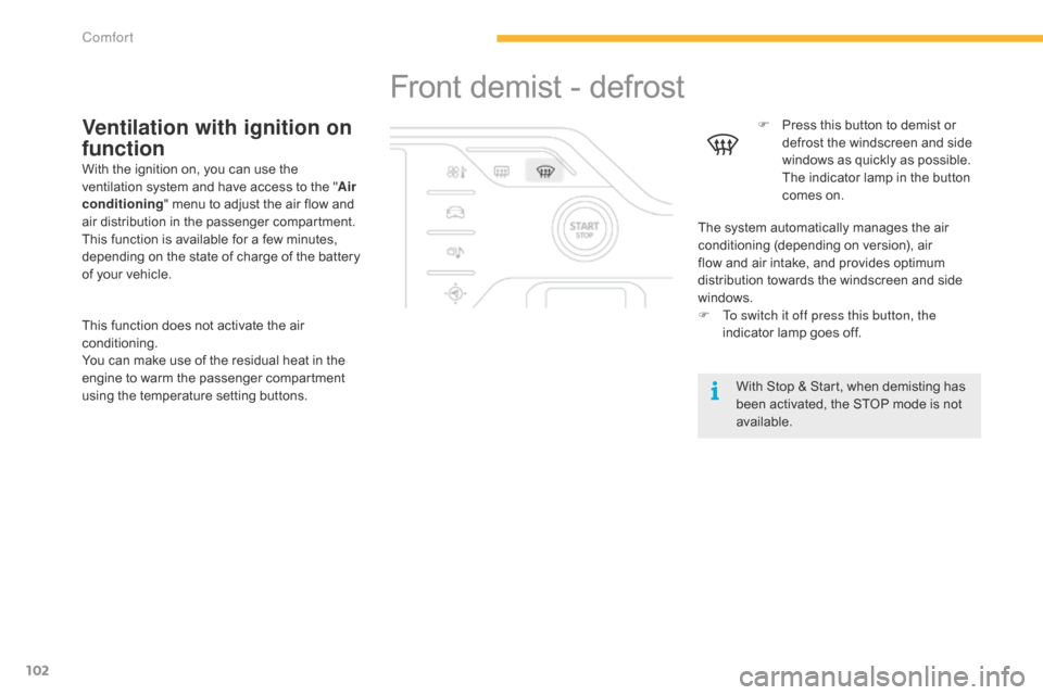
F Press this button to demist or d
efrost the windscreen and side
w
indows as quickly as possible.
T
he indicator lamp in the button
c
omes on.
With
Stop & Start, when demisting has
b
een activated, the STOP mode is not
a
vailable.
The
system automatically manages the air
c
onditioning (depending on version), air
f
low
and
air intake, and provides optimum
d
istribution towards the windscreen and side
w
indows.
F
T
o switch it off press this button, the
indicator
lamp goes off.Ventilation with ignition on
function
With the ignition on, you can use the ventilation system and have access to the "Air
conditioning "
menu to adjust the air flow and
a
ir distribution in the passenger compartment.
This
function is available for a few minutes,
d
epending on the state of charge of the battery
o
f your vehicle.
This
function does not activate the air
c
onditioning.
You
can make use of the residual heat in the
e
ngine to warm the passenger compartment
u
sing the temperature setting buttons.
Comfort
Page 110 of 420

108
Removable console
The removable console is a portable storage space secured to the lower centre console.
I t has a sliding lid, an open storage space and two cup holders.
F
R
aise the locking control located at the
f
ront of the console.
F
W
ith one hand, lift the front part of the
c
onsole.
F
W
ith the other hand, grasp the rear part to
r
elease the removable console.F
C
arry out these operations in reverse
order.
Ensure that the console has locked
i
nto place.
When
not fixed to its carrier, the
r
emovable console should be stowed
i
n the boot. It could become a projectile
i
n the event of a sudden stop or violent
im
pact.
Releasing the removable
consoleRefitting the removable
console
Comfort
Page 114 of 420

112
Storage boxes
F Raise the grip and lower the storage box c
ove r.
Opening
Do not place heavy objects in the boxes.
Depending
on equipment, storage boxes are
l
ocated under the front seats.
Storage belo
w
t
he steering wheel
This storage compartment below the steering w
heel is intended for stowing your vehicle's
han
dbook
pa
ck.
Comfort
Page 115 of 420

113
Rear fittings
Aircraft-style rear tables
These tables, fitted to the backs of the front seats, incorporate a cup-holder recess A and a
r
etaining strap B.
F
P
ull the table downwards to open.
F
T
o stow the table, raise it until the latch
locks.
For safety reasons, these tables collapse
downwards
if excessive pressure is exerted on
t
hem. Reading
lamps C may be fitted in the front seat b
ackrests, behind the tables. They illuminate t
he sur face of the tables without disturbing the
o
ther
p
assengers.
They
can be used only while the table is down.
F
P
ress the "on/off " button to turn the lamp
o
n or off.
Individual reading lamps
Rear table stowedRear table opened
3
Comfort
Page 119 of 420

117
Boot fittings
1. Luggage cover blind (
see details on a following page)
2.
T
o r c h
(
see details on a following page)
3.
C
oncertina
b
oards
4.
1
2 V socket (maximum power: 120 Watts)
5.
A
rm rest with cup holder and storage
spa
ce
6.
R
etaining
s
traps
7.
L
ocation for stowing the luggage cover
b
lind
8.
O
pen
s
torage
9.
L
ower lashing eyes
10.
U
pper eyes (fixings for the boot net)
The
boot net fixing eyes 10,
located
a
t the level of the parcel shelf, are not
intended
for lashing loads or securing
l
uggage.
3
Comfort
Page 120 of 420

118
Luggage cover roller
In the 5 -seat configuration, it is installed behind t
he second-row seats, with the third-row seats
f
olded away.
In
the 7-seat configuration, it is stowed behind
t
he third row seats.
Installation
F Position the left and right hand ends of the r
oller in cut-out A,
with the mobile flap at
t
he front.
F
P
ull out the blind until it reaches the boot
p
illars.
F
I
nsert the guides of the blind into the rails
o
n the pillars B .
Removal
F Disengage the roller guides from the rails i
n the pillars B .
F
G
uide the blind as it is reeled in.
F
U
nlock the roller by pressing one of
t
he grips located at the ends of the reel
sup
port.
The
mobile
flap
allows
passengers
in
t
he
second
row
to
place
their
seats
in
t
he
"comfort"
position.
Comfort
Page 121 of 420

119
Stowing behind the 3rd row seats
To fold the 3rd row seats with the roller
stowed
at
the
rear, it is necessary to raise the
c
oncertina
boards in order to allow access to
t
he
seat
locking controls (red straps).
F
E
nsure
that
the
3rd row seats are folded.
F
F
old
the
first
two
concertina boards.
F
I
nstall
the
roller
in
the space above the arm
r
est,
one
side
after the other, inclining it
s
li g ht l y.
F
S
lide
the
roller
as
far as it will go, up to the
c
ut-outs
provided
at the back of the boot,
w
ith
the
two
flaps
directed downwards.
F
U
nfold
the
third
row seats.
The
folded
concertina
boards can be
p
ositioned
horizontally or vertically.
3
Comfort
Page 131 of 420

129
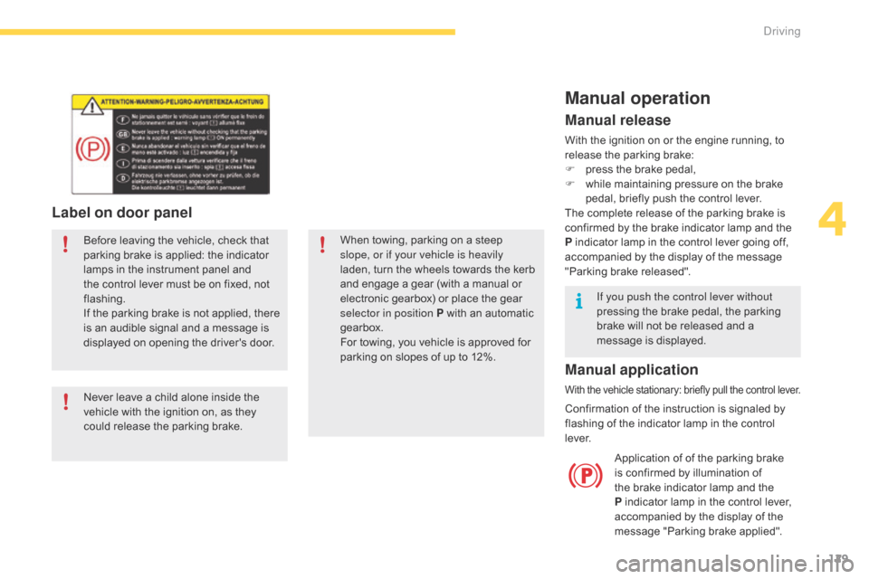
Label on door panel
Before leaving the vehicle, check that parking brake is applied: the indicator
l
amps in the instrument panel and
t
he control lever must be on fixed, not
f
lashing.
If
the parking brake is not applied, there
i
s an audible signal and a message is
d
isplayed on opening the driver's door.
Never
leave a child alone inside the
v
ehicle with the ignition on, as they
c
ould release the parking brake.When
towing, parking on a steep s
lope, or if your vehicle is heavily
laden,
turn the wheels towards the kerb
a
nd engage a gear (with a manual or
e
lectronic gearbox) or place the gear
s
elector in position P with an automatic
g
earbox.
For
towing, you vehicle is approved for
p
arking on slopes of up to 12%.
Manual operation
Application of of the parking brake is confirmed by illumination of
t
he brake indicator lamp and the
P
indicator lamp in the control lever,
a
ccompanied by the display of the
m
essage "Parking brake applied".
Manual release
With the ignition on or the engine running, to release the parking brake:
F
p
ress the brake pedal,
F
w
hile maintaining pressure on the brake
p
edal, briefly push the control lever.
The
complete release of the parking brake is
c
onfirmed by the brake indicator lamp and the
P
indicator lamp in the control lever going off,
a
ccompanied by the display of the message
"
Parking brake released".
If you push the control lever without
pressing
the brake pedal, the parking
b
rake will not be released and a
m
essage is displayed.
Manual application
With the vehicle stationary: briefly pull the control lever.
Confirmation of the instruction is signaled by f
lashing of the indicator lamp in the control
l
eve r.
4
Driving
Page 134 of 420

132
Emergency braking
In the event of a failure of the main service brake or in an exceptional situation (e.g. driver
t
aken ill, under instruction, etc) a continuous
p
ull on the control lever will brake the vehicle.
B
raking takes place while the control lever is
b
eing pulled. It is interrupted if the control lever
i
s
r
eleased.
The
ABS and DSC systems provide stability of
t
he vehicle during emergency braking.
If
the emergency braking malfunctions, the
m
essage "Parking brake control faulty" will be
d
isplayed.
If
a failure of the ABS and DSC systems
o
ccurs, signalled by the illumination of one
o
r both warning lamps in the instrument
p
anel, then stability of the vehicle is no longer
g
uaranteed.
In
this event, stability must be assured by the
d
river by repeating alternate "pull-release"
a
ctions on the control lever until the vehicle is
immobilised. The
emergency braking should only be
u
sed in an exceptional situation.
Repeat
this
procedure
to
reactivate
automatic
ope
ration.
Reactivation
of
automatic
operation
is
c
onfirmed
by
the
indicator
lamp
in
the
i
nstrument
panel
going
off.
Deactivating automatic
operation
In some situations, such as very cold weather o r towing (caravan, recovery), it may be
n
ecessary to deactivate automatic operation of
t
he system.
F
S
tart the engine.
F
A
pply the parking brake with the control
l
ever, if it is released.
F
T
ake your foot off the brake pedal.
F
P
ush and hold the control lever in the
r
elease direction for at least 10 seconds
a
nd no more than 15 seconds.
F
R
elease the control lever.
F
P
ress and hold the brake pedal.
F
P
ull the control lever in the apply direction
f
or 2 seconds.
Deactivation
of the automatic functions
i
s confirmed by illumination of this
i
ndicator lamp in the instrument panel.
F
R
elease the control lever and the brake
ped
al. From
this point the parking brake can only b
e applied and released manually using the
c
ontrol lever.
Driving
Page 143 of 420

141
Automatic gearbox
This gearbox offers two driving modes.
- a utomated mode for automatic
m
anagement of the gears by the gearbox,
w
ithout any action on the part of the driver,
-
m
anual
mode for sequential gear changing
b
y the driver using the steering mounted
p
addles.
P.
Pa
rk.
-
I
mmobilisation of the vehicle, parking brake
a
pplied or released.
-
S
tarting the engine.
R.
R
everse.
-
R
eversing, vehicle stationary and engine at
i
dle.
N.
N
eutral.
-
I
mmobilisation of the vehicle, parking brake
a
pplied.
-
S
tarting the engine.
D.
A
utomatic
ope
ration.
M.
M
anual operation with sequential changing
o
f the six gears.Gear selector lever
To select position P, move the gear s
elector to the highest position
(
towards R),
then push it for wards and
t
hen to the left.
Only
engage it when the vehicle is at a
c
omplete stop. In this position, the front
w
heels are locked. Ensure that the gear
s
elector is correctly positioned.
To
move the gear selector, switch on
t
he ignition or start the engine.
If
the battery is not sufficiently charged,
i
t is not possible to move the gear
s
elector.
To
come out of position P
, move the
g
ear selector to the right to the desired
p
osition, while keeping your foot on the
b
rake
ped
al.
It
is
possible
to
change
from
one
mode
t
o
the
other
at
any
time.
With
the
automated
mode,
you
can
t
emporarily
take
control
of
the
gear
c
hanges
at
any
time.
4
Driving