clock Citroen C4 PICASSO 2015 2.G Owner's Manual
[x] Cancel search | Manufacturer: CITROEN, Model Year: 2015, Model line: C4 PICASSO, Model: Citroen C4 PICASSO 2015 2.GPages: 420, PDF Size: 10.72 MB
Page 205 of 420
203
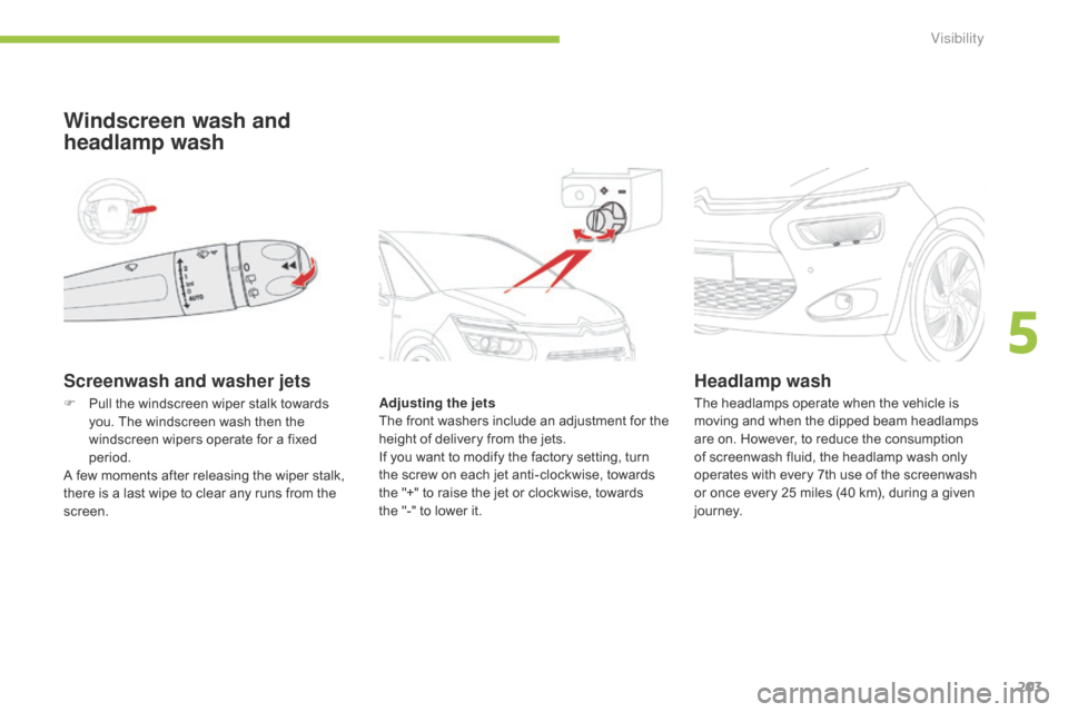
Screenwash and washer jets
Windscreen wash and
headlamp wash
Adjusting the jets
The f ront w ashers i nclude a n a djustment f or t he
h
eight of delivery from the jets.
If
you want to modify the factory setting, turn
t
he screw on each jet anti-clockwise, towards
t
he "+" to raise the jet or clockwise, towards
t
he "-" to lower it.
Headlamp wash
F Pull the windscreen wiper stalk towards y
ou. The windscreen wash then the
w
indscreen wipers operate for a fixed
p
eriod.
A
few moments after releasing the wiper stalk,
t
here is a last wipe to clear any runs from the
sc
reen. The
headlamps operate when the vehicle is m
oving and when the dipped beam headlamps
a
re on. However, to reduce the consumption
o
f screenwash fluid, the headlamp wash only
o
perates with every 7th use of the screenwash
o
r once every 25 miles (40 km), during a given
j
o u r n ey.
5
Visibility
Page 262 of 420
260
Taking out the spare wheelThe spare wheel is supported by a carrier underneath t he v ehicle.
Access to the spare wheel*
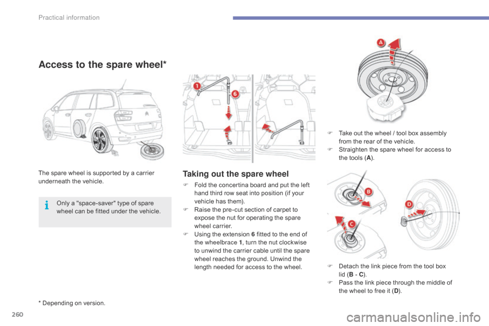
F Take out the wheel / tool box assembly f
rom the rear of the vehicle.
F
S
traighten the spare wheel for access to
t
he tools (A ).
F
F
old
the
concertina
board
and
put
the
left
h
and
third
row
seat
into
position
(if
your
v
ehicle
has
them).
F
R
aise
the
pre-cut
section
of
carpet
to
e
xpose
the
nut
for
operating
the
spare
w
heel
carrier.
F
U
sing
the
extension
6
fitted
to
the
end
of
t
he wheelbrace 1 ,
turn
the
nut
clockwise
t
o
unwind
the
carrier
cable
until
the
spare
w
heel
reaches
the
ground.
Unwind
the
l
ength
needed
for
access
to
the
wheel.
Only
a
"space-saver"
type
of
spare
w
heel
can
be
fitted
under
the
vehicle.
*
Depending
on
version. F
D
etach the link piece from the tool box
l
id (B - C ).
F
P
ass the link piece through the middle of
t
he wheel to free it (D ).
Practical information
Page 263 of 420
261
A puncture wheel from the vehicle cannot be fitted under the vehicle. It
m
ust
b
e
c
arried
i
n
t
he
b
oot.
U
se
a
c
over
t
o protect the boot.
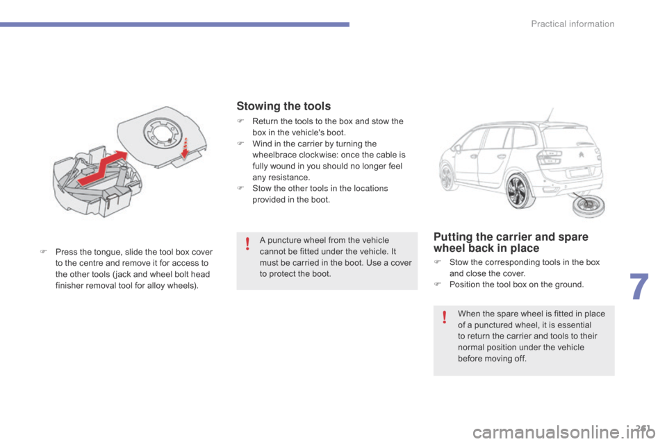
F
P
ress
the
tongue,
slide
the
tool
box
cover
t
o
the
centre
and
remove
it
for
access
to
t
he
other
tools
( jack
and
wheel
bolt
head
f
inisher
removal
tool
for
alloy
wheels).Putting the carrier and spare
wheel back in place
F Stow the corresponding tools in the box a
nd close the cover.
F
P
osition the tool box on the ground.
Stowing the tools
F Return the tools to the box and stow the b
ox in the vehicle's boot.
F
W
ind in the carrier by turning the
w
heelbrace clockwise: once the cable is
f
ully wound in you should no longer feel
an
y
r
esistance.
F
S
tow the other tools in the locations
provided
in the boot.
When
the spare wheel is fitted in place
o
f a punctured wheel, it is essential
t
o return the carrier and tools to their
n
ormal position under the vehicle
b
efore moving off.
7
Practical information
Page 264 of 420

262
F Insert the link piece in the aperture in the t
ool box (B
- C). F
I
nsert the centre guide into the middle of
t
he wheel.
F
P
lace the wheel / tool box assembly under
t
he rear of the vehicle.
F
C
entre and position the spare wheel on the
t
ool box (D ). F
R
aise the wheel / tool box assembly
u
nderneath the vehicle by turning the
c
arrier drive nut anticlockwise using the
w
heelbrace and the extension.
F
T
ighten fully. When the cable is fully wound
i
n, rotation of the nut no longer presents
an
y
r
esistance.
F
C
heck that the wheel is horizontally flat a
gainst the floor.
F
S
traighten the wheel.
F
P
ass the link piece through the middle of
t
he wheel (
A ).
Practical information
Page 273 of 420

271
The direction indicator bulb is located below the front lamp.
F
T
urn the bulb holder a quarter turn anti-
clockwise.
F
R
emove the bulb holder.
F
C
hange the failed bulb.
For
reassembly, carry out these operations in
r
everse
o
rder.
Direction indicators Front foglamps
F Unclip the finisher by pulling at the top.
F R emove the two screws to remove the unit.
F
T
urn the bulb holder a quarter turn.
F
R
emove the bulb holder.
F
C
hange the failed bulb.
For
reassembly, carry out these operations in
r
everse order, pressing on the finisher to refit it.
Faster
flashing
of
a
direction
indicator
w
arning
lamp
(left
or
right)
indicates
a
f
ailed
bulb
on
that
side.
Direction indicators (light
emitting diodes - LED)
For the replacement of this type of lamp, c ontact a CITROËN dealer or a qualified
w
orkshop.
7
Practical information
Page 275 of 420

273
Lamps on the tailgate
Model with LED lamps
Identify
the
failed
bulb.
F
O
pen
the
boot.
F
R
emove
the
access
cover.
Model with conventional bulb lamps
F
R
emove
the
three
lamp
fixing
screws
A .
F
D
isconnect
the
lamp
connector.
F
C
arefully
remove
the
lamp
from
the
outside
b
y
pressing
the
retaining
clip
B .
F
T
urn the bulb holder a quarter of a turn
a
nti-clockwise and pull the bulb out.
F
C
hange the bulb.
For
reassembly, carry out these operations in
r
everse
o
rder.
7
Practical information
Page 277 of 420

275
Lamps on the tailgateModel with LED lamps
Model with conventional bulb lamps
Identify
the
failed
bulb.
F
O
pen
the
boot.
F
R
emove
the
access
cover. F
R
emove
the
three
lamp
fixing
screws
A .
F
D
isconnect
the
lamp
connector.
F
C
arefully
r
emove
t
he
l
amp
f
rom
i
ts
h
ousing.
F
T
urn
the
bulb
holder
a
quarter
of
a
turn
a
nti-clockwise
and
pull
the
bulb
out.
F
C
hange
the
bulb.
For
reassembly,
carry
out
these
operations
in
r
everse
o
rder.
7
Practical information
Page 321 of 420
319
Recommendations on storage
AdBlue® freezes at about -11°C and d
eteriorates above 25°C. It is recommended
t
hat
bottles be stored in a cool area and
p
rotected from direct sunlight.
Under
these conditions, the additive can be
k
ept
for
at least a year.
If
the
additive has frozen, it can be used once it
h
as
completely thawed out.
Procedure
Before topping-up, ensure that the vehicle is parked on a flat and level sur face.
In
wintry conditions, ensure that the
t
emperature of the vehicle is above -11°C.
O
ther wise, by freezing, the AdBlue
® cannot
be
poured
into
its
tank.
Park
your
vehicle in a
w
armer
area
for
a
few
hours
to
allow the top-up
t
o
be
carried
out.
F
P
ress
the
START/STOP
button
to switch
o
ff
the
engine. F
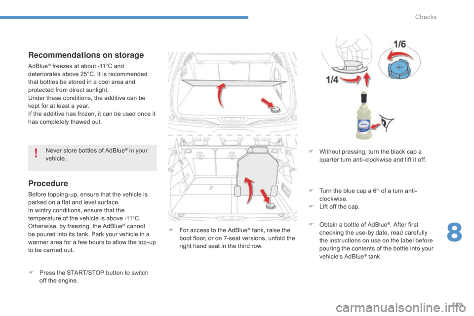
F or access to the AdBlue® tank, raise the b
oot
floor,
or
on
7-seat
versions, unfold the
r
ight
hand
seat
in
the
third
row.
Never
store
bottles
of
AdBlue
® in your
vehicle. F
W ithout pressing, turn the black cap a
q
uarter turn anti-clockwise and lift it off.
F
T
urn the blue cap a 6
th of a turn anti-
c
lockwise.
F
L
ift
off
the
cap.
F
O
btain
a
bottle
of
AdBlue
®. After first c
hecking
the
use-by
date,
read carefully
t
he instructions on use on the label before
pouring
the
contents
of
the bottle into your
v
ehicle's
Ad
Blue
® tank.
8
Checks
Page 322 of 420
320
Important: if your vehicle's Ad
Blue® tank is completely empty - w
hich
is
confirmed by the alert
m
essages and the impossibility of
s
tarting
the engine, you must add at
l
east
3.8 litres (so two 1.89 litre bottles).
Never
dispose of AdBlue
® additive b
ottles
in
the
household
waste. Place
t
hem
in
a
special
container provided
t
his
p
urpose
o
r
t
ake
t
hem
t
o
y
our
d
ealer.
Important:
w
hen topping up after
running out of additive ,
signalled
b
y
the
message
"Top
up
emissions
a
dditive:
Starting
prevented", you must
w
ait
for
approximately
5
minutes before
s
witching
on
the
ignition,
without
opening the driver's door, unlocking
the vehicle, placing the key of the
"Keyless Entr y and Star ting" system
inside the vehicle or inser ting the
electronic key in the reader.
Switch
on
the
ignition,
wait for
1
0 seconds,
then
start
the engine.
If
any
additive
is
split
or
splashed,
wash
i
mmediately
w
ith
c
old
w
ater
o
r
w
ipe
w
ith
a
damp
cloth.
If
the
additive
has
crystallised,
clean
it
o
ff
using
a
sponge
and
hot
water.
F
A
fter
emptying
the
bottle,
wipe
away
any
s
pillage
around
the
tank
filler
using
a
damp
c
loth.
F
R
efit
the
blue
cap
to
the
tank
and
turn
it
a
6th of a turn clockwise, to its stop.
F
R
efit the black cap and turn it a quarter of
a
turn clockwise without pressing. Ensure
t
hat the indicator on the cap lines up with
t
he indicator on the support. F
D
epending on equipment, return the spare
w
heel and/or the storage box to the bottom
o
f the boot.
F
R
efit the boot carpet and close the tailgate.
Checks