ECU CITROEN C5 AIRCROSS 2020 Handbook (in English)
[x] Cancel search | Manufacturer: CITROEN, Model Year: 2020, Model line: C5 AIRCROSS, Model: CITROEN C5 AIRCROSS 2020Pages: 292, PDF Size: 8.59 MB
Page 111 of 292

109
Recommended child
seats
Range of recommended child seats which are
secured using a three-point seat belt .
Group 0+: from bir th to 13
kg
L1
"RÖMER Baby-Safe Plus"
Installed in the "rearward facing" position. Groups 2
and 3: from 15 to 36 kg
L5
"RÖMER KIDFIX"
Can be fitted to the vehicle's ISOFIX mountings.
The child is restrained by the seat belt.
A version with a
removable backrest may be
used for children weighing more than 25
kg.
However, for better protection, use a
booster
seat with backrest for all children weighing up to 36
kg.
5
Safety
Page 112 of 292
110
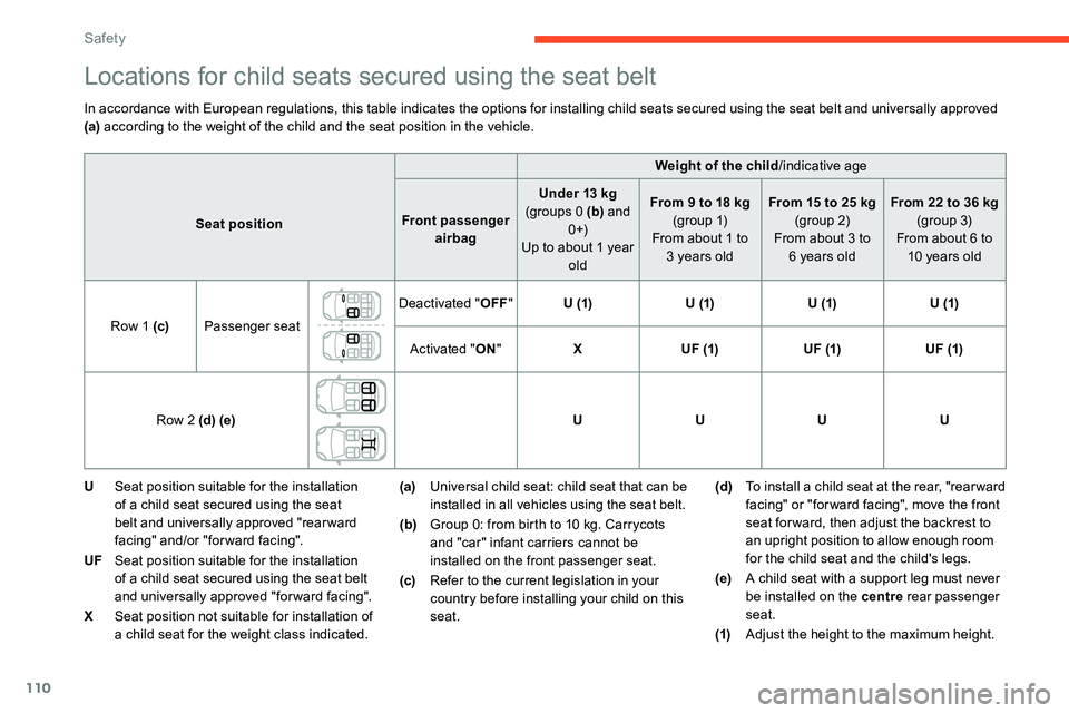
Locations for child seats secured using the seat belt
In accordance with European regulations, this table indicates the options for installing child seats secured using the seat belt and universally approved
(a) according to the weight of the child and the seat position in the vehicle.
U Seat position suitable for the installation
of a
child seat secured using the seat
belt and universally approved "rear ward
facing" and/or "forward facing".
UF Seat position suitable for the installation
of a
child seat secured using the seat belt
and universally approved "forward facing".
X Seat position not suitable for installation of
a
child seat for the weight class indicated. (a)
Universal child seat: child seat that can be
installed in all vehicles using the seat belt.
(b) Group 0: from birth to 10
kg. Carrycots
and "car" infant carriers cannot be
installed on the front passenger seat.
(c) Refer to the current legislation in your
country before installing your child on this
seat. (d)
To install a
child seat at the rear, "rear ward
facing" or "for ward facing", move the front
seat for ward, then adjust the backrest to
an upright position to allow enough room
for the child seat and the child's legs.
(e) A child seat with a
support leg must never
be installed on the centre rear passenger
seat.
(1) Adjust the height to the maximum height.
Weight of the child
/indicative age
Seat position Front passenger
airbag Under 13
kg
(groups 0 (b) and
0 +)
Up to about 1
year
old From 9
to 18 kg
(g r o u p 1)
From about 1
to
3
years oldFrom 15
to 25 kg
(group 2)
From about 3
to
6
years oldFrom 22
to 36 kg
(group 3)
From about 6
to
10
years old
Row 1 (c) Passenger seat Deactivated "
OFF" U (1) U (1)U (1)U (1)
Activated " ON" X U F (1) U F (1)U F (1)
Row 2 (d) (e) UUUU
Safety
Page 113 of 292

111
"ISOFIX" mountings
The seats, shown below, are fitted with ISOFIX
compliant mountings:
The mountings comprise three rings for each
seat: ISOFIX child seats are fitted with two latches
which are secured on the two rings A
.
Some seats also have an upper strap which is
attached to ring B .
To secure the child seat to the TOP TETHER :
F
r
emove and stow the head restraint before
installing the child seat on the seat (refit it
once the child seat has been removed),
F
p
ass the strap of the child seat behind
the seat backrest, centring it between the
apertures for the head restraint rods,
F
s
ecure the upper strap hook to ring B,
F
t
ighten the upper strap.When fitting an ISOFIX child seat to the
left-hand rear seat of the bench seat,
before fitting the seat, first move the
centre rear seat belt towards the middle
of the vehicle, so as to avoid the seat
interfering with the operation of the seat
belt.
-
t
wo rings A , located between the vehicle
seat backrest and cushion, indicated by
a
marking, Front seat
Rear seats
-
o
ne ring B, located behind the seat and
indicated by a
marking, referred to as the
TOP TETHER for fixing the upper strap.
This system prevents the child seat from tipping
for ward in the event of a
front impact.
This ISOFIX mounting system ensures fast,
reliable and safe fitting of the child seat in your
vehicle.
5
Safety
Page 114 of 292

112
Recommended ISOFIX
child seats
Also consult the user guide from the child
seat's manufacturer to find out how to
install and remove the seat. For information about the installation
possibilities for ISOFIX child seats in your
vehicle, refer to the summary table."
RÖMER Baby- Safe Plus and its ISOFIX
base"
(size category: E )
Group 0+: from bir th to 13 kg
Installed "rearward facing" using an ISOFIX base which is attached to rings A .
Is only installed on the front passenger seat or on the outer rear seats.
The base has a support leg, height-
adjustable, which rests on the vehicle's floor. This child seat can also be secured with
a
seat belt. In this case, only the shell is used
and attached to the vehicle seat using the three-point seat belt. "
RÖMER Duo Plus ISOFIX "
(size category: B1 )
Group 1: from 9 to 18 kg
Installed only in the "forward facing" position. Is attached to rings A and ring B , referred to
as TOP TETHER, using an upper strap.
Is only installed on the front passenger seat
or on the outer rear seats. The head restraint on the outer rear seat must be fully raised. Three shell angles: sitting, reclining, lying down.
This child seat can also be used on seats
not equipped with ISOFIX mountings. In this case, it must be secured to the vehicle seat using the three-point seat belt. Adjust the
front seat of the vehicle so that the child's feet do not touch the backrest.
An incorrectly installed child seat
compromises the child's safety in the
event of an accident.
Strictly obser ve the fitting instructions
provided in the user guide supplied with
the child seat.
Safety
Page 116 of 292
114
XSeat not suitable for installing an ISOFIX
seat or carrycot of the weight group
indicated.
(a) Refer to the current legislation in your
country before installing a
child at this
seat position.
(b) Tilt the seat backrest to 45°, then install
the child seat.
Straighten the backrest until it contacts
the child seat's backrest.
(c) To install a
child seat on a rear seat,
"rearward facing" or "forward facing",
adjust the rear seat to the fully back
position with the backrest tilted.
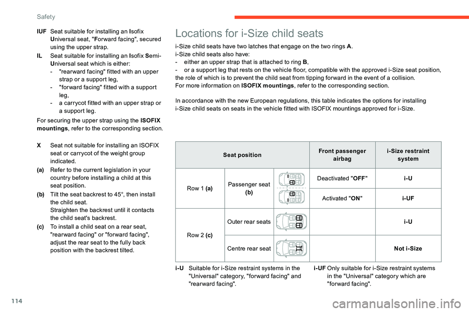
Locations for i-Size child seats
i-Size child seats have two latches that engage on the two rings A .
i-Size child seats also have:
-
e
ither an upper strap that is attached to ring B ,
-
o
r a support leg that rests on the vehicle floor, compatible with the approved i-Size seat position,
the role of which is to prevent the child seat from tipping for ward in the event of a
collision.
For more information on ISOFIX mountings , refer to the corresponding section.
In accordance with the new European regulations, this table indicates the options for installing
i-Size child seats on seats in the vehicle fitted with ISOFIX mountings approved for i-Size.
For securing the upper strap using the ISOFIX
mountings , refer to the corresponding section.
IUF
Seat suitable for installing an I sofix
U niversal seat, " For ward facing", secured
using the upper strap.
IL Seat suitable for installing an I sofix Semi-
U niversal seat which is either:
-
"
rear ward facing" fitted with an upper
strap or a
support leg,
-
"
for ward facing" fitted with a
support
leg,
-
a c
arrycot fitted with an upper strap or
a
support leg. Seat positionFront passenger
airbag i- Size restraint
system
Row 1 (a) Passenger seat
(b) Deactivated "
OFF" i-U
Activated " ON" i-UF
Row 2 (c) Outer rear seats
i-U
Centre rear seat Not i- Size
i-U Suitable for i-Size restraint systems in the
"Universal" category, "forward facing" and
"rearward facing". i-UF
Only suitable for i-Size restraint systems
in the "Universal" category which are
"forward facing".
Safety
Page 139 of 292
137
Maintenance
Clean the bumpers and door mirrors and
the field of vision of the cameras regularly.
When washing your vehicle at high
pressure, direct the spray from at least
30 cm away from the radar, sensors and
cameras.
Mats
The use of mats not approved by
CITROËN may inter fere with the operation
of the speed limiter or cruise control.
To avoid any risk of jamming the pedals:
F
e
nsure that the mat is secured
c o r r e c t l y,
F
n
ever fit one mat on top of another.Speed Limit recognition
and recommendation
Refer to the General recommendations on
the use of driving and manoeuvring aids .
This system displays the maximum authorised
speed in the instrument panel, according to
the speed limits in the country in which you are
driving, using:
-
S
peed limit signs detected by the camera.
-
S
peed limit details from the navigation
system mapping.
You should update your navigation
mapping regularly in order to receive
accurate speed limit information from the
system.
-
S
igns detected by the camera indicating the
area of a
junction:
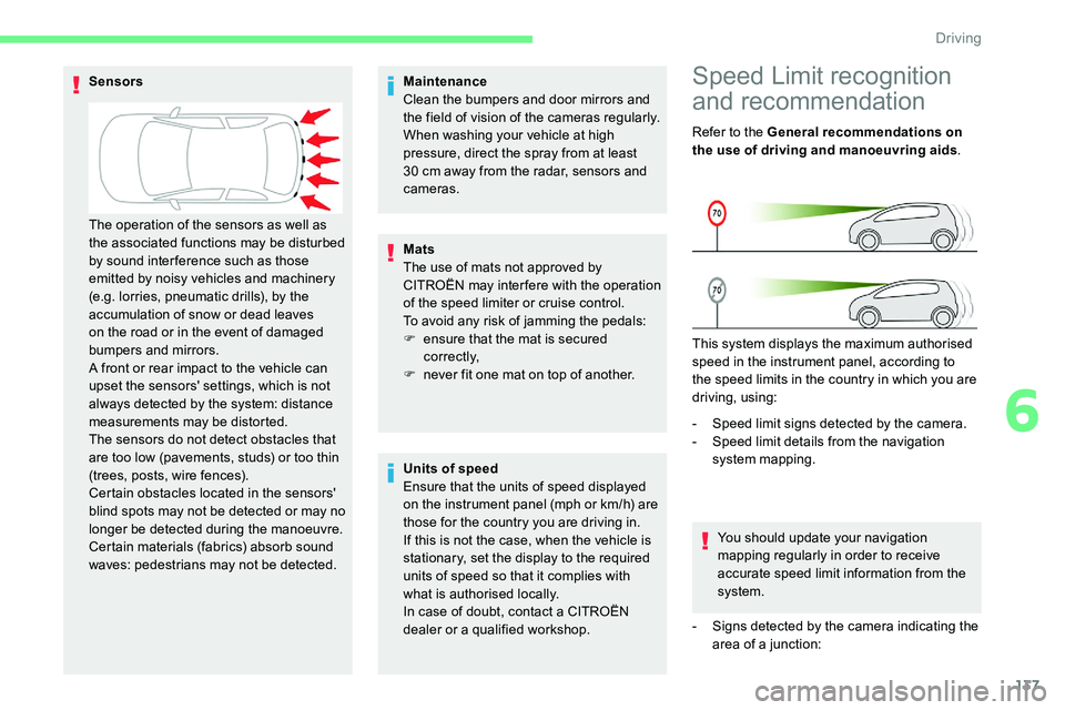
Sensors
Units of speed
Ensure that the units of speed displayed
on the instrument panel (mph or km/h) are
those for the country you are driving in.
If this is not the case, when the vehicle is
stationary, set the display to the required
units of speed so that it complies with
what is authorised locally.
In case of doubt, contact a
CITROËN
dealer or a
qualified workshop.
The operation of the sensors as well as
the associated functions may be disturbed
by sound inter ference such as those
emitted by noisy vehicles and machinery
(e.g. lorries, pneumatic drills), by the
accumulation of snow or dead leaves
on the road or in the event of damaged
bumpers and mirrors.
A front or rear impact to the vehicle can
upset the sensors' settings, which is not
always detected by the system: distance
measurements may be distorted.
The sensors do not detect obstacles that
are too low (pavements, studs) or too thin
(trees, posts, wire fences).
Certain obstacles located in the sensors'
blind spots may not be detected or may no
longer be detected during the manoeuvre.
Certain materials (fabrics) absorb sound
waves: pedestrians may not be detected.
6
Driving
Page 185 of 292

183
Towing device with
quickly detachable towball
Presentation
1.Carrier.
2. Protective plug.
3. Connection socket.
4. Safety eye.
5. Detachable towball.
6. Locking/unlocking wheel.
7. Security key lock.
8. Key reference label. Trailers with LED lamps are not
compatible with the wiring harness of this
device.
To know the Technical data
, and in
particular the towable weights for your
vehicle, refer to the corresponding section.
To ensure complete safety while driving
with a
Towing device, refer to the
corresponding section.
A.
Locked position (the green marks are
opposite each other); the wheel is in
contact with the towball (no gap).
B. Unlocked position (red mark opposite
the green mark); the wheel is no longer
in contact with the towball (gap of around
5 m m).Before each use
Check that the towball is correctly fitted,
verifying the follow points:
-
t
he green mark on the wheel is in line
with the green mark on the towball,
-
t
he wheel is in contact with the towball
(position A ),
-
t
he security key lock is closed and the
key removed; the wheel can no longer
be operated,
-
t
he towball must not be able to move in
its carrier; test by shaking it with your
hand.
If the towball is not locked, the trailer can
detach – accident risk!
7
Practical information
Page 189 of 292
187
It is strongly recommended that before
you leave, you practise fitting the snow
chains on a level and dry sur face.
Avoid driving with snow chains on roads
that have been cleared of snow to avoid
damaging your vehicle's tyres and the
road sur face. If your vehicle is fitted with
alloy wheels, check that no part of the
chain or its fixings is in contact with the
wheel rim.
Use only the chains designed to be fitted to the
type of wheel fitted to your vehicle: Original tyre size Maximum link size
215/65
R17 9
mm
235/55
R18
cannot be fitted with chains
205/55 R19 9 mm
For more information on snow chains, contact
a
CITROËN dealer or a qualified workshop.
Fitting roof bars
As a safety measure and to avoid
d amaging the roof, it is essential to use
the transverse bars approved for your
vehicle.
Obser ve the instructions on fitting and use
contained in the guide supplied with the
roof bars.
Sunroof
Check that the load does not pass below
the roof bars so that it does not impede
the movements of the sunroof.
Recommendations
F
D
istribute the load uniformly, taking
care to avoid overloading one of the
sides.
F
A
rrange the heaviest part of the load
as close as possible to the roof.
F
S
ecure the load firmly and fit a warning
flag if the load overhangs the vehicle.
F
D
rive gently: the vehicle will be more
susceptible to the effects of side winds
(stability may be affected).
F
R
emove the roof bars once they are no
longer needed. Maximum load distributed over the
transverse roof bars, for a
loading height
not exceeding 40 cm (except bicycle
carrier): 75 kg.
As this value may change, please verify
the maximum load quoted on the guide
supplied with the roof bars.
If the height exceeds 40
cm, adapt the
speed of the vehicle to the profile of the
road to avoid damaging the roof bars and
the fixings on the vehicle.
Be sure to refer to national legislation in
order to comply with the regulations for
transporting objects which are longer than
the vehicle.
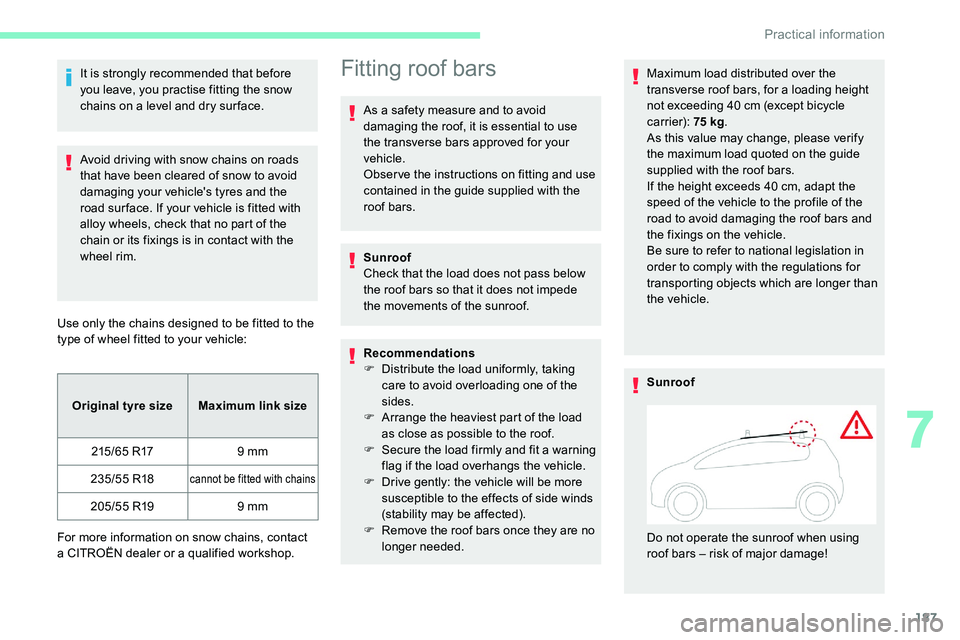
Sunroof
Do not operate the sunroof when using
roof bars – risk of major damage!
7
Practical information
Page 190 of 292

188
Bonnet
The location of the interior bonnet release
lever prevents opening the bonnet when
the left-hand front door is shut.When the engine is hot, handle the
exterior safety catch and the bonnet
stay with care (risk of burns), using the
protected area.
When the bonnet is open, take care not to
damage the safety catch.
Do not open the bonnet under very windy
conditions.
The cooling fan may star t after
switching off the engine: take care
with articles and clothing that might be
caught by the fan blades.
Opening
F Open the left-hand front door.
Before doing anything under the bonnet,
deactivate the Stop & Start system to
avoid the risk of injury related to an
automatic change to START mode. F
P
ull the release lever, located at the bottom
of the door aperture, towards you.
Version without longitudinal
bars
The roof bar fixings include a lug to be fitted
i nto the hole at each fixing point.
Version with longitudinal
bars
You must fit the transverse bars to the
longitudinal bars at the engraved markings on
the longitudinal bars.
To install the roof bars, you must secure them
only to the four fixing points on the roof frame.
These points are concealed by the vehicle's
doors when they are closed.
Practical information
Page 201 of 292
199
The jack must only be used to change
a wheel with a damaged or punctured tyre.
Do not use any jack other than the one
supplied with this vehicle.
If the vehicle does not have its original
jack, contact a
CITROËN dealer or
a
qualified workshop to obtain the correct
jack for it.
The jack meets European standards,
as defined in the Machinery Directive
2006/42/CE.
The jack does not require any
maintenance.
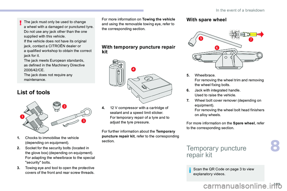
List of tools
1. Chocks to immobilise the vehicle
(depending on equipment).
2. Socket for the security bolts (located in
the glove box) (depending on equipment).
For adapting the wheelbrace to the special
"security" bolts.
3. Towing eye and tool to open the protective
covers of the front and rear screw threads. For more information on Towing the vehicle
and using the removable towing eye, refer to
the corresponding section.
With temporary puncture repair
kit
For further information about the Temporary
puncture repair kit , refer to the corresponding
section.
With spare wheel
For more information on the Spare wheel , refer
to the corresponding section.
4.
12
V compressor with a
cartridge of
sealant and a
speed limit sticker.
For temporary repair of a
tyre and to
adjust the tyre pressure. 5.
Wheelbrace.
For removing the wheel trim and removing
the wheel fixing bolts.
6. Jack with integrated handle.
Used to raise the vehicle.
7. Wheel bolt cover remover (depending on
equipment).
For removing the wheel bolt head finishers
on alloy wheels.
Temporary puncture
repair kit
Scan the QR Code on page 3 to view
e xplanatory videos.
8
In the event of a breakdown