change wheel CITROEN C5 AIRCROSS 2020 Handbook (in English)
[x] Cancel search | Manufacturer: CITROEN, Model Year: 2020, Model line: C5 AIRCROSS, Model: CITROEN C5 AIRCROSS 2020Pages: 292, PDF Size: 8.59 MB
Page 154 of 292

152
Conditions for operation
- The adaptive cruise control must be active.
- T he vehicle must be travelling in a traffic
lane clearly delimited by lines on both sides.
-
T
he ESC system must be operating.
-
T
he ASR /DSC systems must not be
deactivated.
-
N
o trailer detected.
-
A s
pare wheel of the "space-saver" type
must not be in use.
-
T
he vehicle must not be subject to strong
lateral accelerations.
-
T
he direction indicators must not be
activated.
Activation/Deactivation
The state of the system stays in the
memory when the ignition is switched off.
The colour of the symbol depends on the
operating state of the system: (grey colour)
At least one of the operating
conditions is not met, the system is
paused.
(green colour)
All operating conditions are met, the
system is active. If the driver no longer wishes to benefit from
the system for a
while, they can deactivate it by
pressing the button again.
The indicator lamp in the button goes off and
the symbol disappears from the instrument
panel.
Cruise control
The driver must hold the steering wheel
properly.
When cruise control is activated, the symbol is
displayed in green: by small steering actions,
the system directs the vehicle and keeps it in
the position chosen by the driver, in the traffic
lane.
The driver can feel movements in the steering
wheel.
This position is not necessarily the centre of
the lane.
The driver can change the position of the
vehicle at any time, by turning the steering
wheel. When the driver feels that the vehicle's
position is appropriate, whilst keeping hands
on the steering wheel, they must release the
pressure to let the system resume control of the
steering, but the vehicle is not centred within
the lane automatically.
This function is primarily suitable for driving on
motor ways and main roads.
F With the adaptive cruise control activated, press this
button.
The action is confirmed by:
-
I
llumination of the indicator lamp in the button in green.
-
D
isplay of the following symbol in the instrument panel.
(orange colour)
The system has a fault.
Driving
Page 163 of 292
161
The following situations may interfere with
the operation of the system or prevent it
from working:
-
p
oor visibility (inadequate lighting of
the road, falling snow, heavy rain,
dense fog, etc.),
-
d
azzle (headlamps of an oncoming
vehicle, low sun, reflections on a
damp
road, leaving a
tunnel, alternating
shade and light, etc.),
-
w
indscreen area located in front of the
camera: dirty, misted up, frost-covered,
snow-covered, damaged or covered by
a
s t i c ke r,
-
l
ane markings absent, worn, hidden
(snow, mud) or multiple (roadworks,
e t c .),
-
c
lose to the vehicle ahead (lane
markings not detected),
-
r
oads that are narrow, winding, etc.
Active Lane Departure
Warning System
Refer to the General recommendations on
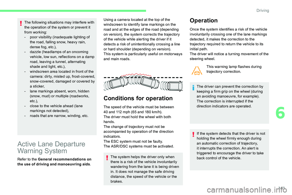
the use of driving and manoeuvring aids .Using a
camera located at the top of the
windscreen to identify lane markings on the
road and at the edges of the road (depending
on version), the system corrects the trajectory
of the vehicle while alerting the driver if it
detects a risk of unintentionally crossing a line
or hard shoulder (depending on version).
This system is particularly useful on motor ways
and main roads.
Conditions for operation
The speed of the vehicle must be between
40 and 112 mph (65 and 180 km/h).
The driver must hold the wheel with both
hands.
The change of trajectory must not be
accompanied by operation of the direction
indicators.
The ESC system must not be faulty.
The ASR /DSC systems must be activated.
The system helps the driver only when
there is a
risk of the vehicle involuntarily
wandering from the lane it is being driven
in. It does not manage the safe driving
distance, the speed of the vehicle or the
brakes.
Operation
Once the system identifies a risk of the vehicle
i nvoluntarily crossing one of the lane markings
detected, it makes the correction to the
trajectory required to return the vehicle to its
initial path.
The driver will notice a
turning movement of the
steering wheel.
This warning lamp flashes during
trajectory correction.
The driver can prevent the correction by
keeping a
firm grip on the wheel (during
an avoiding manoeuvre, for example).
The correction is interrupted if the
direction indicators are operated.
If the system detects that the driver is not
holding the wheel firmly enough during
an automatic correction of trajectory,
it interrupts the correction. An alert is
triggered to encourage the driver to take
back control of the vehicle.
6
Driving
Page 164 of 292

162
Driving situations and
associated alerts
The table below describes the alerts and
messages displayed depending on the driving
situations.
The display of these alerts is not sequential. While the direction indicators are on and for
a few seconds after switching them off, the
system considers that any change of trajectory
is voluntary and no correction is triggered
during this period.
However, with the Blind Spot Monitoring system
activated, if the driver starts changing lanes
and another vehicle is detected in the vehicle's
blind spot, the system will correct the trajectory
of the vehicle even though the direction
indicators are on.
For more information on the Blind Spot
Monitoring system , refer to the corresponding
section. Status of the
function
Indicator
lampDisplay and/
or associated
message
Comments
OFF
(grey)System deactivated.
ON (grey)System active, conditions not met:
-
s
peed below 40 mph (65 km/h),
-
n
o lane marking recognised,
-
A
SR /DSC systems deactivated
or regulation by ESC system in
progress,
-
"
sporty" driving.
ON
(grey)Automatic deactivation/standby of the
system (e.g. detection of a trailer, use of
the "space-saver" spare wheel provided
with the vehicle).
Driving
Page 172 of 292
170
Standard viewZoom view
Obstacles may appear further away than
they actually are.
It is important to check the sides of the
vehicle during the manoeuvre, using the
mirrors.
The rear parking sensors also supplement
the information on the vehicle's
surroundings.
AUTO mode- when shifting out of reverse (the image
remains displayed for 7 seconds),
-
b
y pressing the white arrow in the top left-
hand corner of the touch screen.
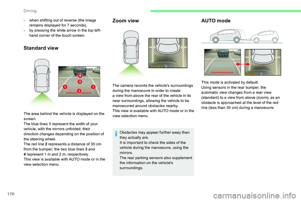
The area behind the vehicle is displayed on the
screen.
The blue lines 1
represent the width of your
vehicle, with the mirrors unfolded; their
direction changes depending on the position of
the steering wheel.
The red line 2
represents a distance of 30 cm
from the bumper; the two blue lines 3
and
4
represent 1 m and 2 m, respectively.
This view is available with AUTO mode or in the
view selection menu. The camera records the vehicle's surroundings
during the manoeuvre in order to create
a
view from above the rear of the vehicle in its
near surroundings, allowing the vehicle to be
manoeuvred around obstacles nearby.
This view is available with AUTO mode or in the
view selection menu. This mode is activated by default.
Using sensors in the rear bumper, the
automatic view changes from a
rear view
(standard) to a
view from above (zoom), as an
obstacle is approached at the level of the red
line (less than 30
cm) during a manoeuvre.
Driving
Page 174 of 292
172
F Select "Panoramic visual aid ".
AUTO mode is displayed by default, with front
vision, if the gearbox is in neutral or with a
gear
engaged, or with rear vision, if reverse is
engaged.
The system is deactivated:
-
a
utomatically above about 19 mph (30 km/h)
(the image disappears temporarily from
12
mph (20 km/h)),
-
b
y pressing the white arrow in the top left-
hand corner of the touch screen.
Standard view Zoom view
Obstacles may appear further away than
they actually are.
It is important to check the sides of the
vehicle during the manoeuvre, using the
mirrors.
The front and rear parking sensors also
provide information on the vehicle's
surroundings.
AUTO mode
With the engine running and the
speed below 12
mph (20 km/h), the
system is activated via the Driving/
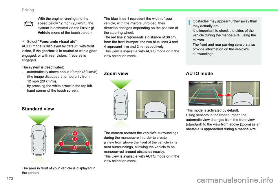
Vehicle menu of the touch screen: The blue lines 1
represent the width of your
vehicle, with the mirrors unfolded; their
direction changes depending on the position of
the steering wheel.
The red line 2
represents a distance of 30 cm
from the front bumper; the two blue lines 3
and
4
represent 1 m and 2 m, respectively.
This view is available with AUTO mode or in the
view selection menu.
The area in front of your vehicle is displayed in
the screen. The camera records the vehicle's surroundings
during the manoeuvre in order to create
a
view from above the front of the vehicle in its
near surroundings, allowing the vehicle to be
manoeuvred around obstacles nearby.
This view is available with AUTO mode or in the
view selection menu. This mode is activated by default.
Using sensors in the front bumper, the
automatic view changes from the front view
(standard) to the view from above (zoom) as an
obstacle is approached during a
manoeuvre.
Driving
Page 189 of 292
187
It is strongly recommended that before
you leave, you practise fitting the snow
chains on a level and dry sur face.
Avoid driving with snow chains on roads
that have been cleared of snow to avoid
damaging your vehicle's tyres and the
road sur face. If your vehicle is fitted with
alloy wheels, check that no part of the
chain or its fixings is in contact with the
wheel rim.
Use only the chains designed to be fitted to the
type of wheel fitted to your vehicle: Original tyre size Maximum link size
215/65
R17 9
mm
235/55
R18
cannot be fitted with chains
205/55 R19 9 mm
For more information on snow chains, contact
a
CITROËN dealer or a qualified workshop.
Fitting roof bars
As a safety measure and to avoid
d amaging the roof, it is essential to use
the transverse bars approved for your
vehicle.
Obser ve the instructions on fitting and use
contained in the guide supplied with the
roof bars.
Sunroof
Check that the load does not pass below
the roof bars so that it does not impede
the movements of the sunroof.
Recommendations
F
D
istribute the load uniformly, taking
care to avoid overloading one of the
sides.
F
A
rrange the heaviest part of the load
as close as possible to the roof.
F
S
ecure the load firmly and fit a warning
flag if the load overhangs the vehicle.
F
D
rive gently: the vehicle will be more
susceptible to the effects of side winds
(stability may be affected).
F
R
emove the roof bars once they are no
longer needed. Maximum load distributed over the
transverse roof bars, for a
loading height
not exceeding 40 cm (except bicycle
carrier): 75 kg.
As this value may change, please verify
the maximum load quoted on the guide
supplied with the roof bars.
If the height exceeds 40
cm, adapt the
speed of the vehicle to the profile of the
road to avoid damaging the roof bars and
the fixings on the vehicle.
Be sure to refer to national legislation in
order to comply with the regulations for
transporting objects which are longer than
the vehicle.
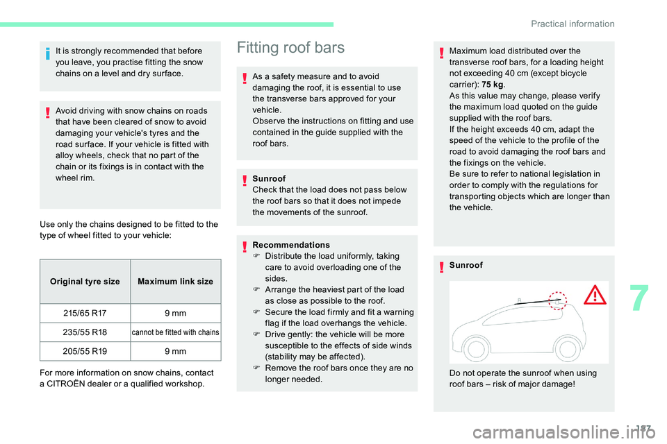
Sunroof
Do not operate the sunroof when using
roof bars – risk of major damage!
7
Practical information
Page 195 of 292
193
If the warning lamp stays on, this indicates
a low Diesel additive level.
For more information on Checking levels ,
refer to the corresponding section.
Following prolonged operation of the
vehicle at very low speed or at idle,
you may, in exceptional circumstances,
notice the emission of water vapour at the
exhaust on acceleration. This does not
affect the behaviour of the vehicle or the
environment.
New vehicle
The first particle filter regeneration
operations may be accompanied by a
"burning" smell, which is per fectly normal.
Manual gearbox
The gearbox does not require any
maintenance (no oil change).
Automatic gearbox
The gearbox does not require any
maintenance (no oil change).
Brake pads
Brake wear depends on the style
of driving, particularly in the case
of vehicles used in town, over short
distances. It may be necessary to
have the condition of the brakes
checked, even between vehicle
services.
Unless there is a
leak in the circuit, a drop in
the brake fluid level indicates that the brake
pads are worn.
After washing the vehicle, dampness, or
in wintry conditions, ice can form on the
brake discs and pads: braking efficiency
may be reduced. Make light brake
applications to dry and defrost the brakes.
Brake disc wear
For information on checking brake
disc wear, contact a CITROËN
dealer or a
qualified workshop.
Electric parking brake
This system does not require any
routine servicing. However, in case
of an issue, do not hesitate to have
the system checked by a
CITROËN
dealer or a
qualified workshop.
For more information on the Electric
parking brake , refer to the corresponding
section.
Wheels and tyres
The pressure must be checked on
all tyres, including the spare wheel,
when the tyres are "cold", at least
once a
month and before a long
j o u r n ey.
The pressures indicated on the tyre pressure
label are valid for "cold" tyres. If you have
driven for more than 10
minutes or more
than 6
miles (10 kilometres) at over 31 mph
(50
km/h), add 0.3 bar (30 kPa) to the values
indicated on the label.
7
Practical information
Page 201 of 292
199
The jack must only be used to change
a wheel with a damaged or punctured tyre.
Do not use any jack other than the one
supplied with this vehicle.
If the vehicle does not have its original
jack, contact a
CITROËN dealer or
a
qualified workshop to obtain the correct
jack for it.
The jack meets European standards,
as defined in the Machinery Directive
2006/42/CE.
The jack does not require any
maintenance.
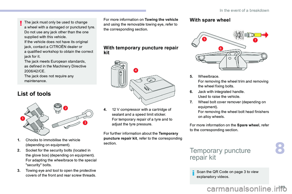
List of tools
1. Chocks to immobilise the vehicle
(depending on equipment).
2. Socket for the security bolts (located in
the glove box) (depending on equipment).
For adapting the wheelbrace to the special
"security" bolts.
3. Towing eye and tool to open the protective
covers of the front and rear screw threads. For more information on Towing the vehicle
and using the removable towing eye, refer to
the corresponding section.
With temporary puncture repair
kit
For further information about the Temporary
puncture repair kit , refer to the corresponding
section.
With spare wheel
For more information on the Spare wheel , refer
to the corresponding section.
4.
12
V compressor with a
cartridge of
sealant and a
speed limit sticker.
For temporary repair of a
tyre and to
adjust the tyre pressure. 5.
Wheelbrace.
For removing the wheel trim and removing
the wheel fixing bolts.
6. Jack with integrated handle.
Used to raise the vehicle.
7. Wheel bolt cover remover (depending on
equipment).
For removing the wheel bolt head finishers
on alloy wheels.
Temporary puncture
repair kit
Scan the QR Code on page 3 to view
e xplanatory videos.
8
In the event of a breakdown
Page 206 of 292
204
Parking the vehicle
Immobilise the vehicle where it does not
block traffic: the ground must be level,
stable and non-slippery.
Apply the parking brake, unless it is
programmed to be in automatic mode;
switch off the ignition and with a manual
gearbox, engage first gear so as to lock
the wheels.
Apply the parking brake, unless it is
programmed to be in automatic mode;
switch off the ignition and with an
automatic gearbox, select mode P so as to
lock the wheels.
Check that the parking brake warning
lamps in the instrument panel are on fixed.
The occupants must get out of the vehicle
and wait where they are safe.
If necessary, place a
chock under the
wheel diagonally opposite the wheel to be
changed.
Never go underneath a
vehicle raised
using a
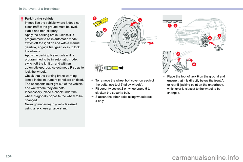
jack; use an axle stand. F
T
o remove the wheel bolt cover on each of
the bolts, use tool 7 (alloy wheels).
F
F
it security socket 2 on wheelbrace 5 to
slacken the security bolt.
F
S
lacken the other bolts using wheelbrace
5
o n l y.F
P
lace the foot of jack 6 on the ground and
ensure that it is directly below the front A
or rear B jacking point on the underbody,
whichever is closest to the wheel to be
changed.
In the event of a breakdown
Page 227 of 292
1
CITROËN Connect Radio
Multimedia audio system –
Applications – Bluetooth®
telephone
Contents
First steps
1
S
teering mounted controls
2
M
enus
3
A
pplications
5
R
adio
5
D
AB (Digital Audio Broadcasting) radio
7
M
edia
8
T
elephone
1
0
Settings
1
4
Frequently asked questions
1
6
The various functions and settings
described differ according to the version
and configuration of the vehicle. For safety reasons and because they
require continued attention on the part of
the driver, the following operations must
be carried out with the vehicle stationary
and the ignition on:
-
Us
ing a
smartphone.
-
P
airing a Bluetooth mobile phone to
the hands-free Bluetooth system of the
audio system.
-
Sm
artphone connection operations for
CarPlay
®, MirrorLinkTM or Android Auto
(certain applications interrupt their
display when the vehicle starts to move
again).
-
T
he configuration of profiles.
The system is protected in such a
way that
it will only operate in the vehicle.
The display of the message Energy
Economy Mode signals that a
change to
standby is imminent.
The link below gives access to the OSS
(Open Source Software) code for the
system.
https://www.groupe-psa.com/fr/oss/
https://www.groupe-psa.com/en/oss/
First steps
With the engine running, a press
mutes the sound.
With the ignition off, a press turns
the system on.
Increase or decrease the volume using
the wheel or the "plus" or "minus" buttons
(depending on the equipment).
Use the buttons on either side of or below the
touch screen for access to the menus, then
press the virtual buttons in the touch screen.
Depending on the model, use the "Source" or
"Menu" buttons on the left of the touch screen
for access to the menus, then press the virtual
buttons in the touch screen.
At all times it is possible to display the rolling
menus by pressing the screen briefly with three
fingers.
All of the touch areas of the screen are white.
For pages with multiple tabs at the bottom of
the screen, it is possible to switch between
pages either by tapping the tab for the desired
page, or by using a
finger, sliding the pages to
the left or to the right.
Press in the grey zone to go back up a
level or
to confirm.
.
CITROËN Connect Radio