ESP CITROEN C6 2005 Owner's Guide
[x] Cancel search | Manufacturer: CITROEN, Model Year: 2005, Model line: C6, Model: CITROEN C6 2005Pages: 223, PDF Size: 4.26 MB
Page 123 of 223
![CITROEN C6 2005 Owners Guide Downloaded from www.Manualslib.com manuals search engine 117
CLUTCH
GEARBOX
TRANSMISSION
CHECKING THE OIL PRESSURE IN THE AM6 AUTOMATIC GEARBOX
Tools.
[1]Flexible pipe and pressure gauge: 4601- TF1 T CITROEN C6 2005 Owners Guide Downloaded from www.Manualslib.com manuals search engine 117
CLUTCH
GEARBOX
TRANSMISSION
CHECKING THE OIL PRESSURE IN THE AM6 AUTOMATIC GEARBOX
Tools.
[1]Flexible pipe and pressure gauge: 4601- TF1 T](/img/9/57744/w960_57744-122.png)
Downloaded from www.Manualslib.com manuals search engine 117
CLUTCH
GEARBOX
TRANSMISSION
CHECKING THE OIL PRESSURE IN THE AM6 AUTOMATIC GEARBOX
Tools.
[1]Flexible pipe and pressure gauge: 4601- TF1 Toolkit 4601-T
[2]Flexible union: (-).0336.X Toolkit 8010-T
IMPERATIVE: Respect the safety and cleanliness requirements.
Preliminary operations.
Remove the air filter housing.
Move aside the pipe (1).
Remove the screw (2).
Screw in the tool [2]in place of the screw (2).
B2CP45GCB2CP45FC
Angl-C6-page101-120-2005 4/02/05 17:25 Page 117
Page 124 of 223
![CITROEN C6 2005 Owners Guide Downloaded from www.Manualslib.com manuals search engine 118
CLUTCH
GEARBOX
TRANSMISSION
CHECKING THE OIL PRESSURE IN THE AM6 AUTOMATIC GEARBOX
WARNING: Clean the flexible pipe of the tool [1] each t CITROEN C6 2005 Owners Guide Downloaded from www.Manualslib.com manuals search engine 118
CLUTCH
GEARBOX
TRANSMISSION
CHECKING THE OIL PRESSURE IN THE AM6 AUTOMATIC GEARBOX
WARNING: Clean the flexible pipe of the tool [1] each t](/img/9/57744/w960_57744-123.png)
Downloaded from www.Manualslib.com manuals search engine 118
CLUTCH
GEARBOX
TRANSMISSION
CHECKING THE OIL PRESSURE IN THE AM6 AUTOMATIC GEARBOX
WARNING: Clean the flexible pipe of the tool [1] each time before use; the different
automatic gearbox oils cannot be intermixed.
Fit the tool [1]on the tool [2].
Perform the following operations:
- Raise the vehicle, wheels hanging.
- Apply the parking brake.
- Start the engine.
- Check the oil pressure.
WARNING: Wait for the gearbox oil to reach a temperature between 58°C and 68°C.
Check the level of oil in the gearbox (see corresponding operation).
NOTE:Check the temperature of the oil using the diagnostic tool in parameter measures.
Gear lever position: D.
Engine speed: Idling.
Principal oil pressure: 3.7 to 4.2 bars.
B1BP3END
Angl-C6-page101-120-2005 4/02/05 17:25 Page 118
Page 125 of 223

Downloaded from www.Manualslib.com manuals search engine 119
CLUTCH
GEARBOX
TRANSMISSION
CHECKING THE OIL PRESSURE IN THE AM6 AUTOMATIC GEARBOX
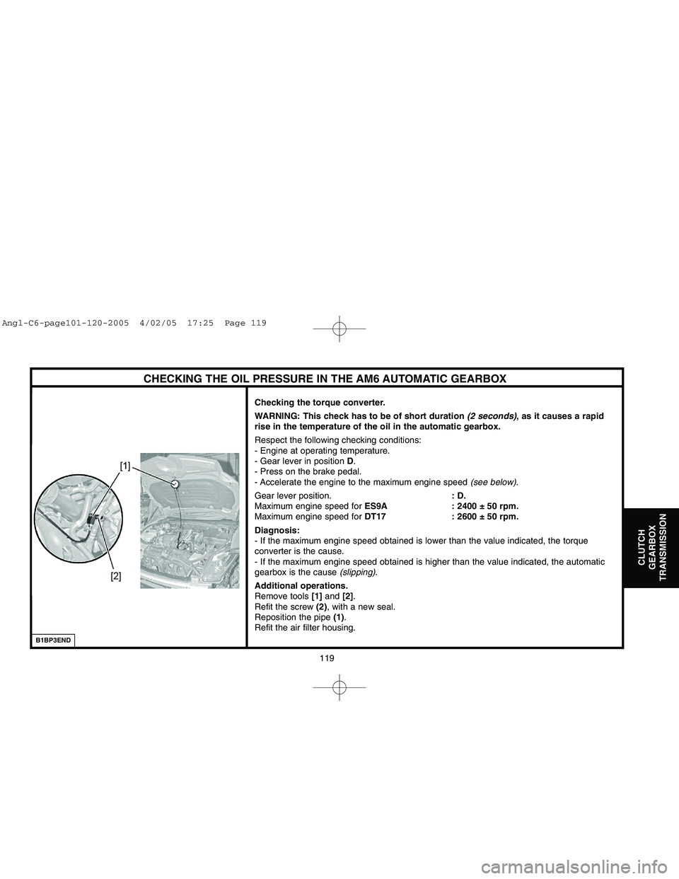
Checking the torque converter.
WARNING: This check has to be of short duration (2 seconds), as it causes a rapid
rise in the temperature of the oil in the automatic gearbox.
Respect the following checking conditions:
- Engine at operating temperature.
- Gear lever in position D.
- Press on the brake pedal.
- Accelerate the engine to the maximum engine speed (see below).
Gear lever position.: D.
Maximum engine speed for ES9A : 2400 ± 50 rpm.
Maximum engine speed for DT17 : 2600 ± 50 rpm.
Diagnosis:
- If the maximum engine speed obtained is lower than the value indicated, the torque
converter is the cause.
- If the maximum engine speed obtained is higher than the value indicated, the automatic
gearbox is the cause (slipping).
Additional operations.
Remove tools [1]and [2].
Refit the screw (2), with a new seal.
Reposition the pipe (1).
Refit the air filter housing.
B1BP3END
Angl-C6-page101-120-2005 4/02/05 17:25 Page 119
Page 131 of 223
![CITROEN C6 2005 Owners Guide Downloaded from www.Manualslib.com manuals search engine AXLES
SUSPENSION
STEERING
125
CHECKING AND ADJUSTING VEHICLE HEIGHT
IMPERATIVE: Respect the safety and cleanliness requirements.
Tools.
[1]Gaug CITROEN C6 2005 Owners Guide Downloaded from www.Manualslib.com manuals search engine AXLES
SUSPENSION
STEERING
125
CHECKING AND ADJUSTING VEHICLE HEIGHT
IMPERATIVE: Respect the safety and cleanliness requirements.
Tools.
[1]Gaug](/img/9/57744/w960_57744-130.png)
Downloaded from www.Manualslib.com manuals search engine AXLES
SUSPENSION
STEERING
125
CHECKING AND ADJUSTING VEHICLE HEIGHT
IMPERATIVE: Respect the safety and cleanliness requirements.
Tools.
[1]Gauge for measuring radius of wheels (5 bolts): 9801-T
[2]Gauge for height under bodyshell: 2305-T
[3] LEXIAstation: 4171-T
[4] PROXIAstation: 4165-T
Preliminary operations.
Check the tyre pressures.
Place the vehicle on a 4 column lift.
Switch on the ignition.
Release the parking brake.
Put the vehicle in the high position.
Put the vehicle in the normal height position (driving height).
During:During the measuring, do not move the vehicle.
Reference heights: REFERENCE = Ignition switched on
Angl-C6-page121-169-2005 4/02/05 17:31 Page 125
Page 135 of 223

Downloaded from www.Manualslib.com manuals search engine AXLES
SUSPENSION
STEERING
129
A < B = Positive figure: + = TOE-IN
A > B = Negative figure: - = TOE-OUTNOTE
VALUES FOR CHECKING AND ADJUSTING AXLE GEOMETRIES
IMPERATIVE: Respect the safety and cleanliness requirements.
Tools.
[1]Gauge for measuring radius of wheels (5 bolts): 9801-T
[2]Gauge for height under bodyshell: 2305-T
WARNING: «Check and adjust the axle geometries at referenceheight».
Conditions for checking and adjusting.
Check the tyre pressures.
Place the vehicle on a 4 column lift.
Check and adjust if necessary the vehicle heights (see corresponding
operation).
Steering rack locked at its zero point (see corresponding operation).
Switch off the ignition before removing the tools from the wheels.
Lower the vehicle.
Start the engine.
Put the vehicle in the high position.
Put the vehicle in the normal height position (driving height).
Stop the engine.
Switch on the ignition.
Check and adjust the front and rear axle geometries at reference
height.
WARNING: Do not switch off the ignition during checking and
adusting of the front and rear axle geometries.
NOTE:Front of vehicle (following the arrow).
B3CP02UC
Angl-C6-page121-169-2005 4/02/05 17:31 Page 129
Page 153 of 223

Downloaded from www.Manualslib.com manuals search engine 147
AXLES
SUSPENSION
STEERING
(9)Front RH wheel travel sensor
The wheel travel sensor defines the angular position of the suspension lower arm.
Identification of the sensors:
- Front RH wheel travel sensor: Yellow.
- Front LH wheel travel sensor: Red.
- Rear RH wheel travel sensor: Green.
- Rear LH wheel travel sensor: Blue.
IMPERATIVE: Before operating on a wheel travel sensor, uncouple its rod so as not to
go past the maximum angular travel (see corresponding operation).
The suspension pressure sensors (7)informs the suspension ECU (CSS)of the pressure in
the hydraulic high pressure pipes of the front suspension.
The sensor (13)informs the suspension ECU (CSS)of the pressure in the hydraulic high
pressure pipes of the rear suspension.
B3BP19ZCB3BP19YC
ACTIVE SUSPENSION WITH VARIABLE DAMPING
Wheel travel sensor
Suspension pressure sensor
Angl-C6-page121-169-2005 4/02/05 17:31 Page 147
Page 168 of 223

Downloaded from www.Manualslib.com manuals search engine 162
AXLES
SUSPENSION
STEERING
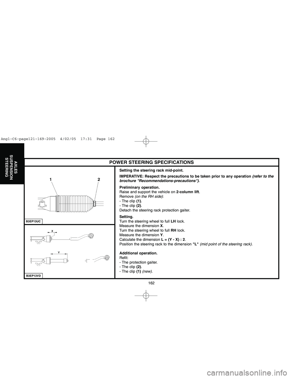
Setting the steering rack mid-point.
IMPERATIVE: Respect the precautions to be taken prior to any operation (refer to the
brochure "Recommendations-precautions").
Preliminary operation.
Raise and support the vehicle on 2-column lift.
Remove (on the RH side):
- The clip (1).
- The clip (2).
Detach the steering rack protection gaiter.
Setting.
Turn the steering wheel to full LHlock.
Measure the dimension X.
Turn the steering wheel to full RHlock.
Measure the dimension Y.
Calculate the dimension L = (Y - X) : 2.
Position the steering rack to the dimension "L"(mid point of the steering rack).
Additional operation.
Refit:
- The protection gaiter.
- The clip (2).
- The clip (1)(new).
B3EP13UCB3EP13VD
POWER STEERING SPECIFICATIONS
Angl-C6-page121-169-2005 4/02/05 17:31 Page 162
Page 174 of 223
![CITROEN C6 2005 Owners Guide Downloaded from www.Manualslib.com manuals search engine 168
AXLES
SUSPENSION
STEERING
Remove:
- The exhaust line (3).
- The tool [6].
Couple the two supply pipes (5)on the distributor valve.
Refit:
- CITROEN C6 2005 Owners Guide Downloaded from www.Manualslib.com manuals search engine 168
AXLES
SUSPENSION
STEERING
Remove:
- The exhaust line (3).
- The tool [6].
Couple the two supply pipes (5)on the distributor valve.
Refit:
-](/img/9/57744/w960_57744-173.png)
Downloaded from www.Manualslib.com manuals search engine 168
AXLES
SUSPENSION
STEERING
Remove:
- The exhaust line (3).
- The tool [6].
Couple the two supply pipes (5)on the distributor valve.
Refit:
- The bracket (7).
- The screw (4), tighten to 0,8 ± 0,1 m.daN.
Retighten the union (6)on the power steering ram; tighten to 1,4 ± 0,35 m.daN.
Refit the exhaust line (3).
Pinch the pipe at "a", using tool [2].
Remove:
- The assembly [3].
- The union [5]on the pipe (2).
- The union [4]on the steering assistance pump.
Couple the pipe (2), using tool [1].
Tighten the pipe (2)to 2 ± 0,2 m.daN.
Refit the bracket (1).
Bleed the hydraulic steering assistance circuit (see corresponding operation).
Top up the level of the LDS fluid (see procedure: drain-fill-bleed the suspension circuit).
B1JP08WDB3EP185D
CHECKING THE STEERING ASSISTANCE PRESSURE (ES9A ENGINE)
Angl-C6-page121-169-2005 4/02/05 17:31 Page 168
Page 175 of 223

Downloaded from www.Manualslib.com manuals search engine 169
AXLES
SUSPENSION
STEERING
Precautions to be taken.
Proceed with care so as to prevent any entry of polluting particles.
IMPERATIVE: Respect the safety and cleanliness requirements.
IMPERATIVE: Fill the LDS fluid reservoir with new fluid: TOTAL LDS.
Bleeding.
Check the level and top up the LDSfluid (see procedure: drain-fill-bleed the suspension circuit).
Apply a pressure of 0.5 barin the LDSfluid reservoir (using tool FACOM 920).
Start the engine.
Wait for the vehicle height to stabilise.
Move the steering in each direction, from lock to lock.
Stop the engine.
Check the level and top up the LDSfluid (see procedure: drain-fill-bleed the suspension circuit).
BLEEDING THE HYDRAULIC STEERING ASSISTANCE CIRCUIT
Angl-C6-page121-169-2005 4/02/05 17:31 Page 169
Page 177 of 223

Downloaded from www.Manualslib.com manuals search engine 171
BRAKES
B3FP7GED
BRAKING SYSTEM: GENERAL SPECIFICATIONS
Braking system
Braking circuit in the form of anX.
Disc brakes at the front and at the rear
(vehicles all types):
- The front brake discs are ventilated.
- The rear brake discs are ventilated.
Electric parking brake (FSE)acting via cables on the
rear wheels.
The compensator and main brake limiter functions are
assured by the ABS REFsystems.
ESPis fitted as standard on the entire range.
NOTE: - REF (EBD) =Electronic Brakeforce
Distribution.
- ESP =Electronic Stability Programme.
Braking circuit
Angl-C6-PAGE170-194-2005 4/02/05 17:35 Page 171