wheel CITROEN C6 2005 Owners Manual
[x] Cancel search | Manufacturer: CITROEN, Model Year: 2005, Model line: C6, Model: CITROEN C6 2005Pages: 223, PDF Size: 4.26 MB
Page 6 of 223
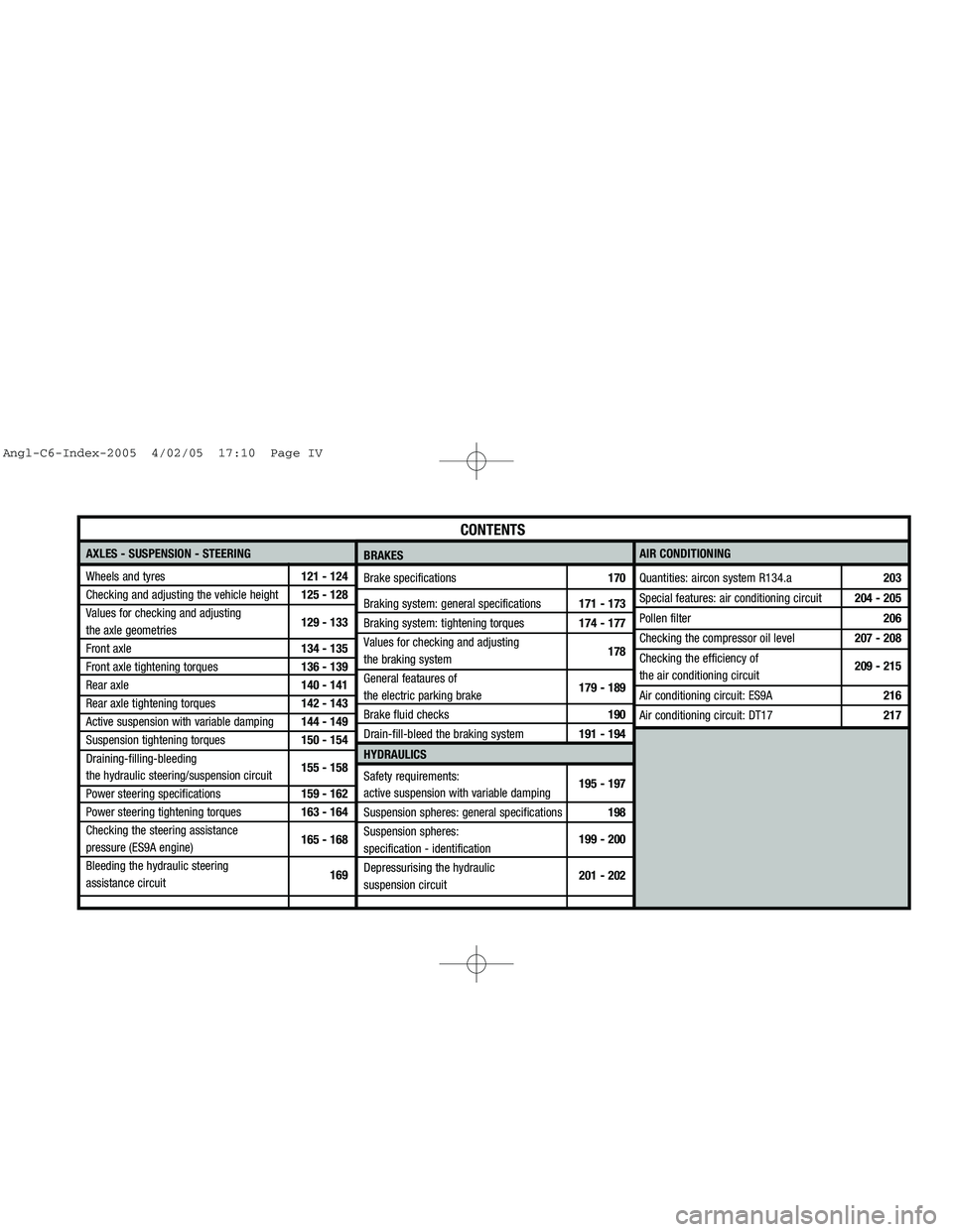
Downloaded from www.Manualslib.com manuals search engine AXLES - SUSPENSION - STEERING
Wheels and tyres121 - 124
Checking and adjusting the vehicle height125 - 128
Values for checking and adjusting
the axle geometries129 - 133
Front axle134 - 135
Front axle tightening torques136 - 139
Rear axle140 - 141
Rear axle tightening torques142 - 143
Active suspension with variable damping144 - 149
Suspension tightening torques150 - 154
Draining-filling-bleeding
the hydraulic steering/suspension circuit155 - 158
Power steering specifications159 - 162
Power steering tightening torques163 - 164
Checking the steering assistance
pressure (ES9A engine)165 - 168
Bleeding the hydraulic steering
assistance circuit169AIR CONDITIONING
Quantities: aircon system R134.a 203
Special features: air conditioning circuit 204 - 205
Pollen filter206
Checking the compressor oil level207 - 208
Checking the efficiency of
the air conditioning circuit209 - 215
Air conditioning circuit: ES9A216
Air conditioning circuit: DT17217
CONTENTS
BRAKES
Brake specifications170
Braking system: general specifications171 - 173
Braking system: tightening torques174 - 177
Values for checking and adjusting
the braking system178
General feataures of
the electric parking brake179 - 189
Brake fluid checks190
Drain-fill-bleed the braking system191 - 194
HYDRAULICS
Safety requirements:
active suspension with variable damping195 - 197
Suspension spheres: general specifications 198
Suspension spheres:
specification - identification199 - 200
Depressurising the hydraulic
suspension circuit201 - 202
Angl-C6-Index-2005 4/02/05 17:10 Page IV
Page 12 of 223
Downloaded from www.Manualslib.com manuals search engine 6
GENERAL
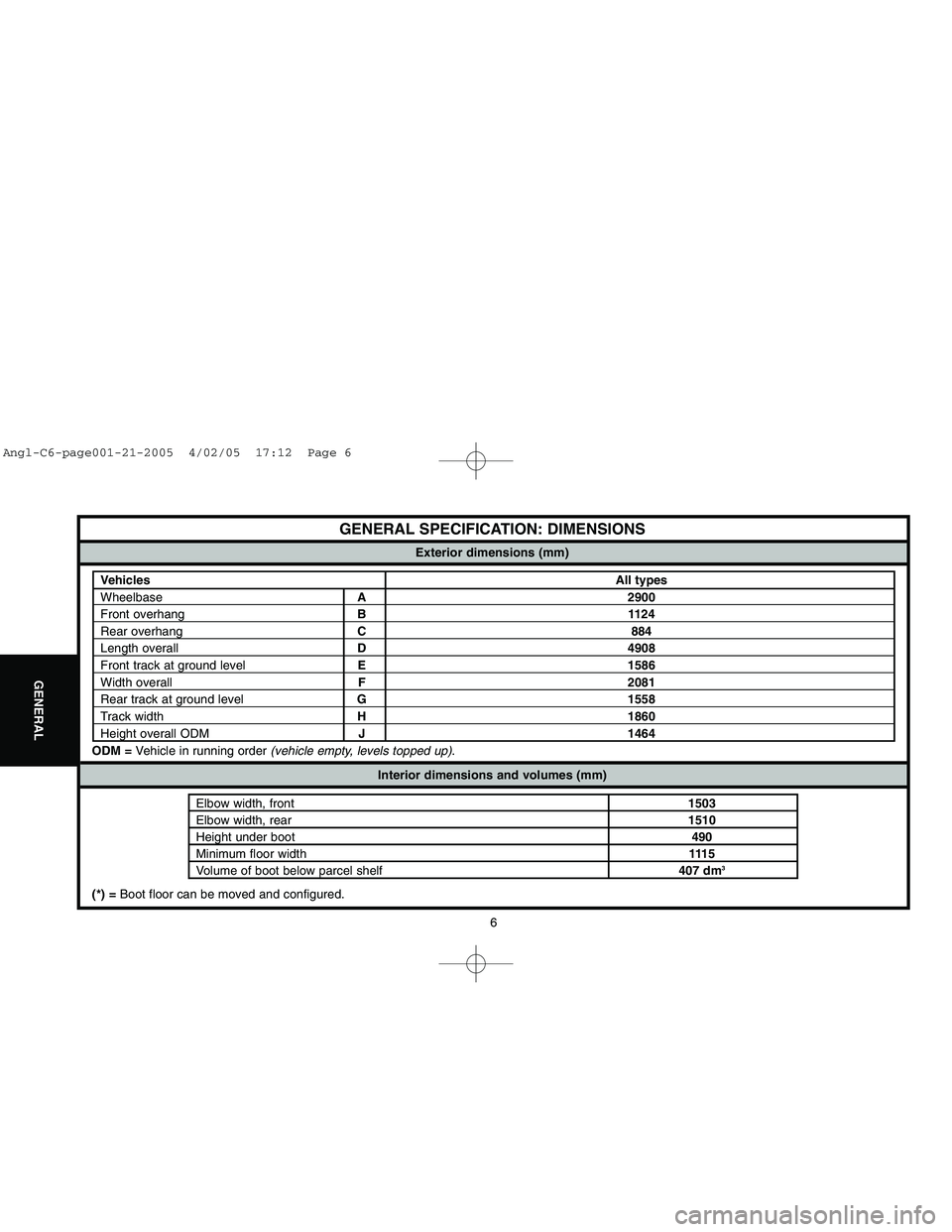
GENERAL SPECIFICATION: DIMENSIONS
ODM =Vehicle in running order (vehicle empty, levels topped up).
Exterior dimensions (mm)
VehiclesAll types
WheelbaseA 2900Front overhangB 1124Rear overhangC 884Length overallD 4908Front track at ground levelE 1586Width overallF 2081Rear track at ground levelG 1558Track widthH 1860
Height overall ODMJ 1464
Interior dimensions and volumes (mm)
Elbow width, front1503Elbow width, rear1510Height under boot490Minimum floor width111 5
Volume of boot below parcel shelf407 dm
3
(*) = Boot floor can be moved and configured.
Angl-C6-page001-21-2005 4/02/05 17:12 Page 6
Page 15 of 223
Downloaded from www.Manualslib.com manuals search engine 9
GENERAL
GENERAL SPECIFICATION: TOWING THE VEHICLE
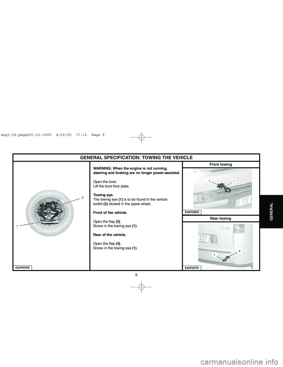
WARNING: When the engine is not running,
steering and braking are no longer power-assisted.
Open the boot.
Lift the boot floor plate.
Towing eye.
The towing eye (1)is to be found in the vehicle
toolkit (2)stowed in the spare wheel.
Front of the vehicle.
Open the flap (3).
Screw in the towing eye (1).
Rear of the vehicle.
Open the flap (4).
Screw in the towing eye (1).
E2AP02RD
Front towingRear towing
E2AP02SDE2AP02TD
Angl-C6-page001-21-2005 4/02/05 17:12 Page 9
Page 16 of 223
Downloaded from www.Manualslib.com manuals search engine 10
GENERAL
GENERAL SPECIFICATION: TOWING THE VEHICLE
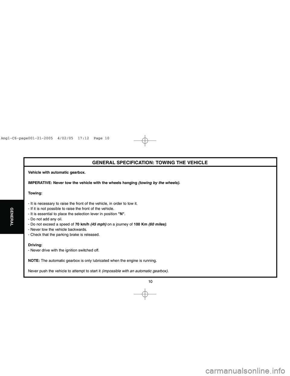
Vehicle with automatic gearbox.
IMPERATIVE: Never tow the vehicle with the wheels hanging (towing by the wheels).
Towing:
- It is necessary to raise the front of the vehicle, in order to tow it.
- If it is not possible to raise the front of the vehicle.
- It is essential to place the selection lever in position "N".
- Do not add any oil.
- Do not exceed a speed of 70 km/h(45 mph)on a journey of 100 Km (60 miles).
- Never tow the vehicle backwards.
- Check that the parking brake is released.
Driving:
- Never drive with the ignition switched off.
NOTE: The automatic gearbox is only lubricated when the engine is running.
Never push the vehicle to attempt to start it (impossible with an automatic gearbox).
Angl-C6-page001-21-2005 4/02/05 17:12 Page 10
Page 18 of 223
Downloaded from www.Manualslib.com manuals search engine 12
GENERAL
LIFTING AND SUPPORTING THE VEHICLE
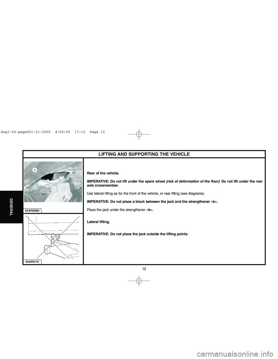
Rear of the vehicle.
IMPERATIVE: Do not lift under the spare wheel (risk of deformation of the floor). Do not lift under the rear
axle crossmember.
Use lateral lifting as for the front of the vehicle, or rear lifting (see diagrams).
IMPERATIVE: Do not place a block between the jack and the strengthener «b».
Place the jack under the strengthener «b».
Lateral lifting.
IMPERATIVE: Do not place the jack outside the lifting points.
E2AP017CE2AP02MD
Angl-C6-page001-21-2005 4/02/05 17:12 Page 12
Page 19 of 223
Downloaded from www.Manualslib.com manuals search engine 13
GENERAL
LIFTING AND SUPPORTING THE VEHICLE
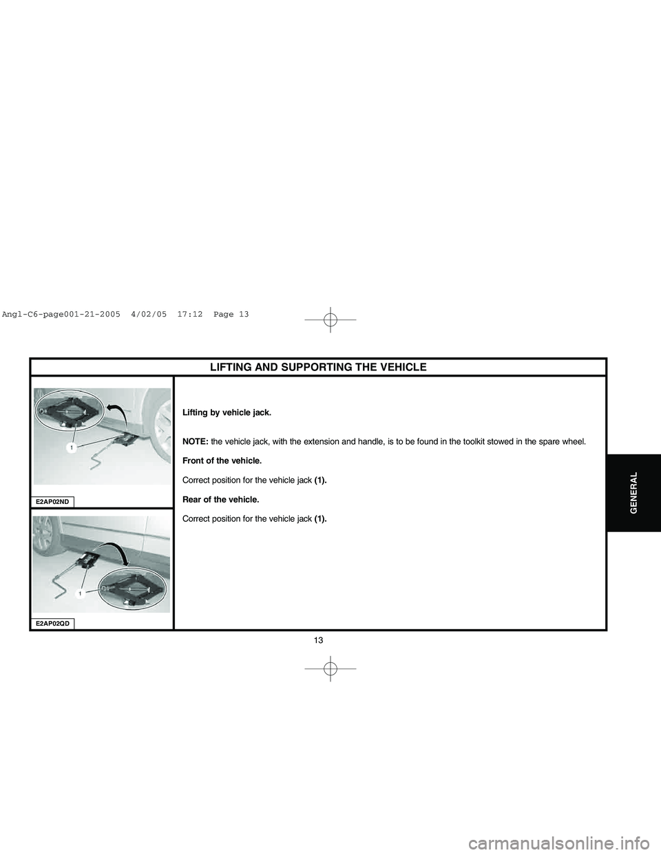
Lifting by vehicle jack.
NOTE: the vehicle jack, with the extension and handle, is to be found in the toolkit stowed in the spare wheel.
Front of the vehicle.
Correct position for the vehicle jack(1).
Rear of the vehicle.
Correct position for the vehicle jack (1).
E2AP02QDE2AP02ND
Angl-C6-page001-21-2005 4/02/05 17:12 Page 13
Page 31 of 223
Downloaded from www.Manualslib.com manuals search engine 25
ENGINE
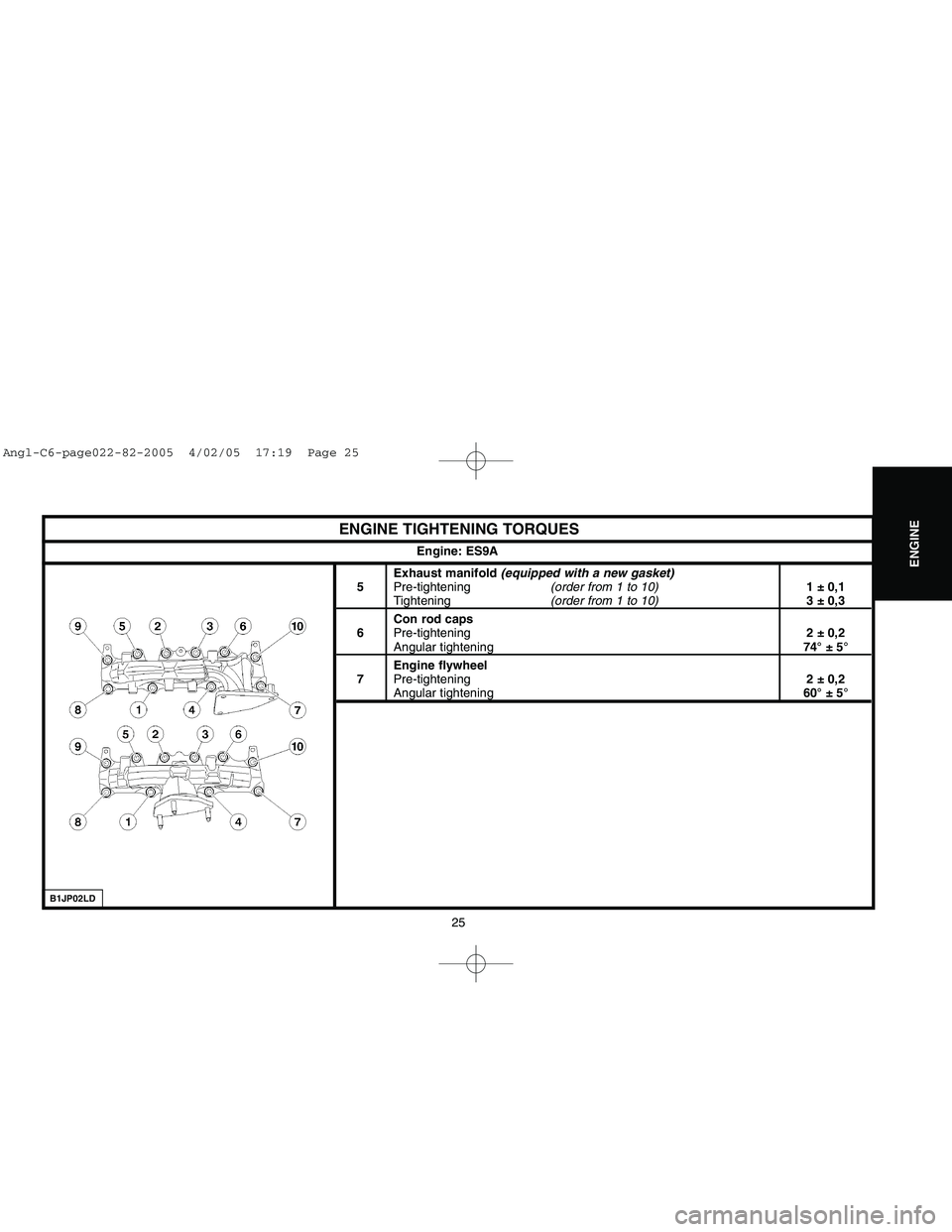
ENGINE TIGHTENING TORQUES
Exhaust manifold (equipped with a new gasket)
5Pre-tightening(order from 1 to 10)1 ± 0,1Tightening(order from 1 to 10)3 ± 0,3
Con rod caps
6Pre-tightening2 ± 0,2Angular tightening74° ± 5°
Engine flywheel
7Pre-tightening2 ± 0,2Angular tightening60° ± 5° Engine: ES9A
B1JP02LD
Angl-C6-page022-82-2005 4/02/05 17:19 Page 25
Page 41 of 223
Downloaded from www.Manualslib.com manuals search engine 35
ENGINE
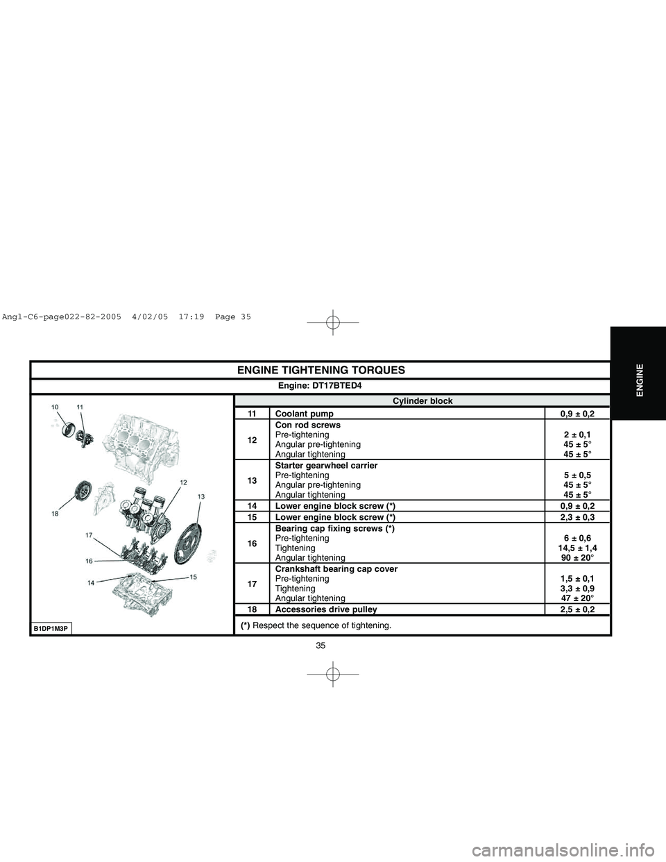
ENGINE TIGHTENING TORQUES
Cylinder block
11 Coolant pump 0,9 ± 0,2
Con rod screws
12Pre-tightening2 ± 0,1
Angular pre-tightening 45 ± 5°
Angular tightening45 ± 5°
Starter gearwheel carrier
13Pre-tightening5 ± 0,5
Angular pre-tightening 45 ± 5°Angular tightening45 ± 5°
14 Lower engine block screw (*) 0,9 ± 0,215 Lower engine block screw (*) 2,3 ± 0,3
Bearing cap fixing screws (*)
16Pre-tightening6 ± 0,6
Tightening14,5 ± 1,4
Angular tightening90 ± 20°
Crankshaft bearing cap cover
17Pre-tightening1,5 ± 0,1
Tightening3,3 ± 0,9Angular tightening 47 ± 20°
18 Accessories drive pulley 2,5 ± 0,2
(*) Respect the sequence of tightening.Engine: DT17BTED4
B1DP1M3P
Angl-C6-page022-82-2005 4/02/05 17:19 Page 35
Page 54 of 223
![CITROEN C6 2005 Owners Manual Downloaded from www.Manualslib.com manuals search engine 48
ENGINE
B1BP3BSD
AUXILIARY EQUIPMENT DRIVE BELT
Engine: ES9A
Tool.
[1] 2 mmdiameter peg: (-).0188-Q1
Removing.
Remove:
- The under-engine sou CITROEN C6 2005 Owners Manual Downloaded from www.Manualslib.com manuals search engine 48
ENGINE
B1BP3BSD
AUXILIARY EQUIPMENT DRIVE BELT
Engine: ES9A
Tool.
[1] 2 mmdiameter peg: (-).0188-Q1
Removing.
Remove:
- The under-engine sou](/img/9/57744/w960_57744-53.png)
Downloaded from www.Manualslib.com manuals search engine 48
ENGINE
B1BP3BSD
AUXILIARY EQUIPMENT DRIVE BELT
Engine: ES9A
Tool.
[1] 2 mmdiameter peg: (-).0188-Q1
Removing.
Remove:
- The under-engine sound-deadening.
- The front RH wheel.
- The RH splash-shield.
- The air duct (linking the air distributor heat exchanger).
Compress the dynamic tensioner roller (1)to free the pegging hole at "a".
Peg the dynamic tensioner roller at "a", using tool [1].
WARNING: Do not compress the dynamic tensioner roller completely (risk
of damage).
WARNING: Mark the direction of fitting of the auxiliary equipment drive belt
if for re-use.
Disengage the auxiliary equipment drive belt from the various pulleys, commencing
at "b"(coolant pump pulley).
Remove:
- The screws (2)and (4).
- The dynamic tensioner roller (1).
- The auxiliary equipment drive belt (3).
ESSENTIAL: Check that the tensioner and guide rollers as well as the
coolant pump can turn freely (without play, without tight spots and without
projections of grease).
Angl-C6-page022-82-2005 4/02/05 17:19 Page 48
Page 55 of 223
Downloaded from www.Manualslib.com manuals search engine 49
ENGINE
B1BP3BVC
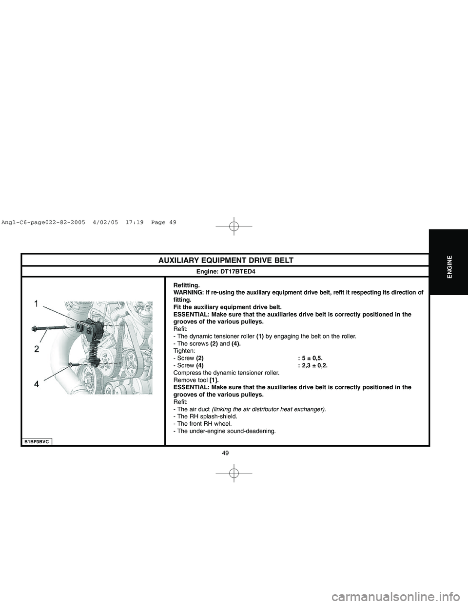
AUXILIARY EQUIPMENT DRIVE BELT
Engine: DT17BTED4
Refitting.
WARNING: If re-using the auxiliary equipment drive belt, refit it respecting its direction of
fitting.
Fit the auxiliary equipment drive belt.
ESSENTIAL: Make sure that the auxiliaries drive belt is correctly positioned in the
grooves of the various pulleys.
Refit:
- The dynamic tensioner roller (1)by engaging the belt on the roller.
- The screws (2)and (4).
Tighten:
- Screw (2) : 5 ± 0,5.
- Screw (4) : 2,3 ± 0,2.
Compress the dynamic tensioner roller.
Remove tool [1].
ESSENTIAL: Make sure that the auxiliaries drive belt is correctly positioned in the
grooves of the various pulleys.
Refit:
- The air duct(linking the air distributor heat exchanger).
- The RH splash-shield.
- The front RH wheel.
- The under-engine sound-deadening.
Angl-C6-page022-82-2005 4/02/05 17:19 Page 49