suspension CITROEN C6 2005 Owners Manual
[x] Cancel search | Manufacturer: CITROEN, Model Year: 2005, Model line: C6, Model: CITROEN C6 2005Pages: 223, PDF Size: 4.26 MB
Page 3 of 223
Downloaded from www.Manualslib.com manuals search engine PRESENTATION
THIS HANDBOOK summarises the specifications, adjustments, checks and special features of CITROËNprivate vehicles, not including UTILITY vehicles for which there exists a
separate handbook.
The handbook is divided into groups representing the main functions:
GENERAL - ENGINE - INJECTION - IGNITION - CLUTCH, GEARBOX, DRIVESHAFTS - AXLES, SUSPENSION, STEERING - BRAKES - HYDRAULICS - AIR CONDITIONING.
Angl-C6-Index-2005 4/02/05 17:10 Page I
Page 5 of 223
Downloaded from www.Manualslib.com manuals search engine GENERAL
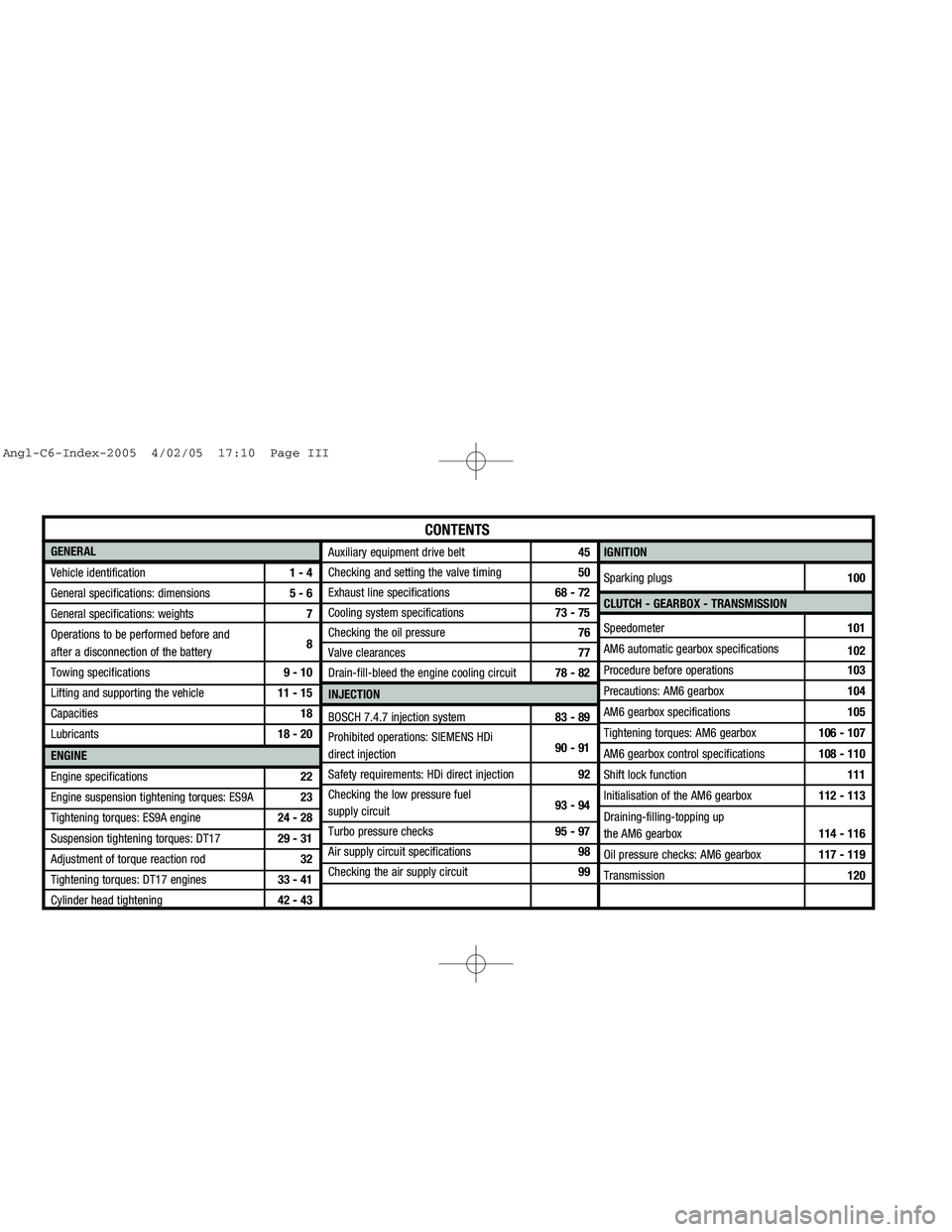
Vehicle identification1 - 4
General specifications: dimensions 5 - 6
General specifications: weights7
Operations to be performed before and
after a disconnection of the battery8
Towing specifications9 - 10
Lifting and supporting the vehicle11 - 15
Capacities18
Lubricants18 - 20
ENGINE
Engine specifications22
Engine suspension tightening torques: ES9A23
Tightening torques: ES9A engine24 - 28
Suspension tightening torques: DT1729 - 31
Adjustment of torque reaction rod32
Tightening torques: DT17 engines33 - 41
Cylinder head tightening42 - 43IGNITION
Sparking plugs100
CLUTCH - GEARBOX - TRANSMISSION
Speedometer101
AM6 automatic gearbox specifications
102
Procedure before operations103
Precautions: AM6 gearbox104
AM6 gearbox specifications105
Tightening torques: AM6 gearbox106 - 107
AM6 gearbox control specifications 108 - 110
Shift lock function111
Initialisation of the AM6 gearbox112 - 113
Draining-filling-topping up
the AM6 gearbox114 - 116
Oil pressure checks: AM6 gearbox117 - 119
Transmission120
CONTENTS
Auxiliary equipment drive belt45
Checking and setting the valve timing50
Exhaust line specifications68 - 72
Cooling system specifications73 - 75
Checking the oil pressure76
Valve clearances77
Drain-fill-bleed the engine cooling circuit78 - 82
INJECTION
BOSCH 7.4.7 injection system83 - 89
Prohibited operations: SIEMENS HDi
direct injection90 - 91
Safety requirements: HDi direct injection92
Checking the low pressure fuel
supply circuit 93 - 94
Turbo pressure checks95 - 97
Air supply circuit specifications98
Checking the air supply circuit99
Angl-C6-Index-2005 4/02/05 17:10 Page III
Page 6 of 223
Downloaded from www.Manualslib.com manuals search engine AXLES - SUSPENSION - STEERING
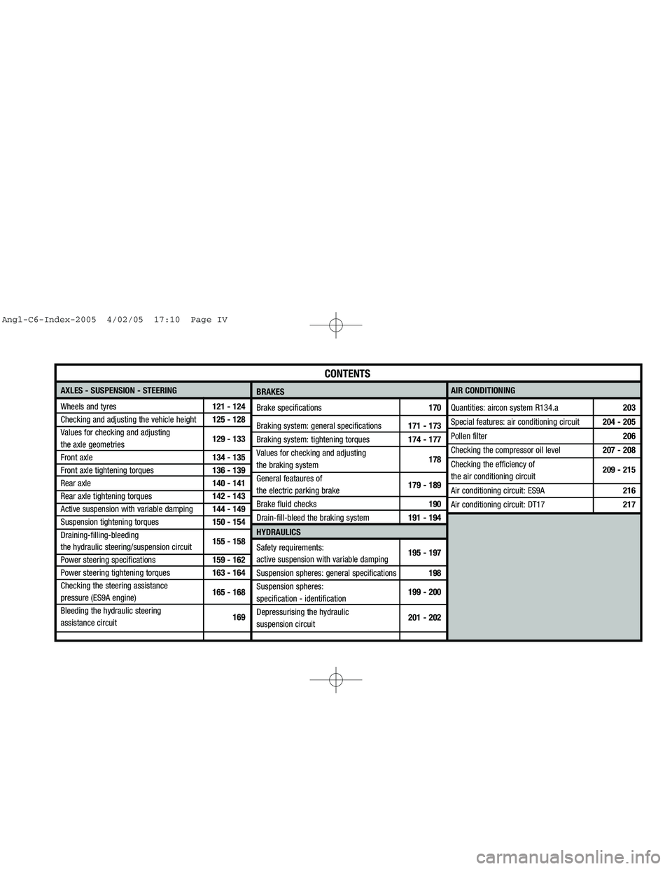
Wheels and tyres121 - 124
Checking and adjusting the vehicle height125 - 128
Values for checking and adjusting
the axle geometries129 - 133
Front axle134 - 135
Front axle tightening torques136 - 139
Rear axle140 - 141
Rear axle tightening torques142 - 143
Active suspension with variable damping144 - 149
Suspension tightening torques150 - 154
Draining-filling-bleeding
the hydraulic steering/suspension circuit155 - 158
Power steering specifications159 - 162
Power steering tightening torques163 - 164
Checking the steering assistance
pressure (ES9A engine)165 - 168
Bleeding the hydraulic steering
assistance circuit169AIR CONDITIONING
Quantities: aircon system R134.a 203
Special features: air conditioning circuit 204 - 205
Pollen filter206
Checking the compressor oil level207 - 208
Checking the efficiency of
the air conditioning circuit209 - 215
Air conditioning circuit: ES9A216
Air conditioning circuit: DT17217
CONTENTS
BRAKES
Brake specifications170
Braking system: general specifications171 - 173
Braking system: tightening torques174 - 177
Values for checking and adjusting
the braking system178
General feataures of
the electric parking brake179 - 189
Brake fluid checks190
Drain-fill-bleed the braking system191 - 194
HYDRAULICS
Safety requirements:
active suspension with variable damping195 - 197
Suspension spheres: general specifications 198
Suspension spheres:
specification - identification199 - 200
Depressurising the hydraulic
suspension circuit201 - 202
Angl-C6-Index-2005 4/02/05 17:10 Page IV
Page 7 of 223
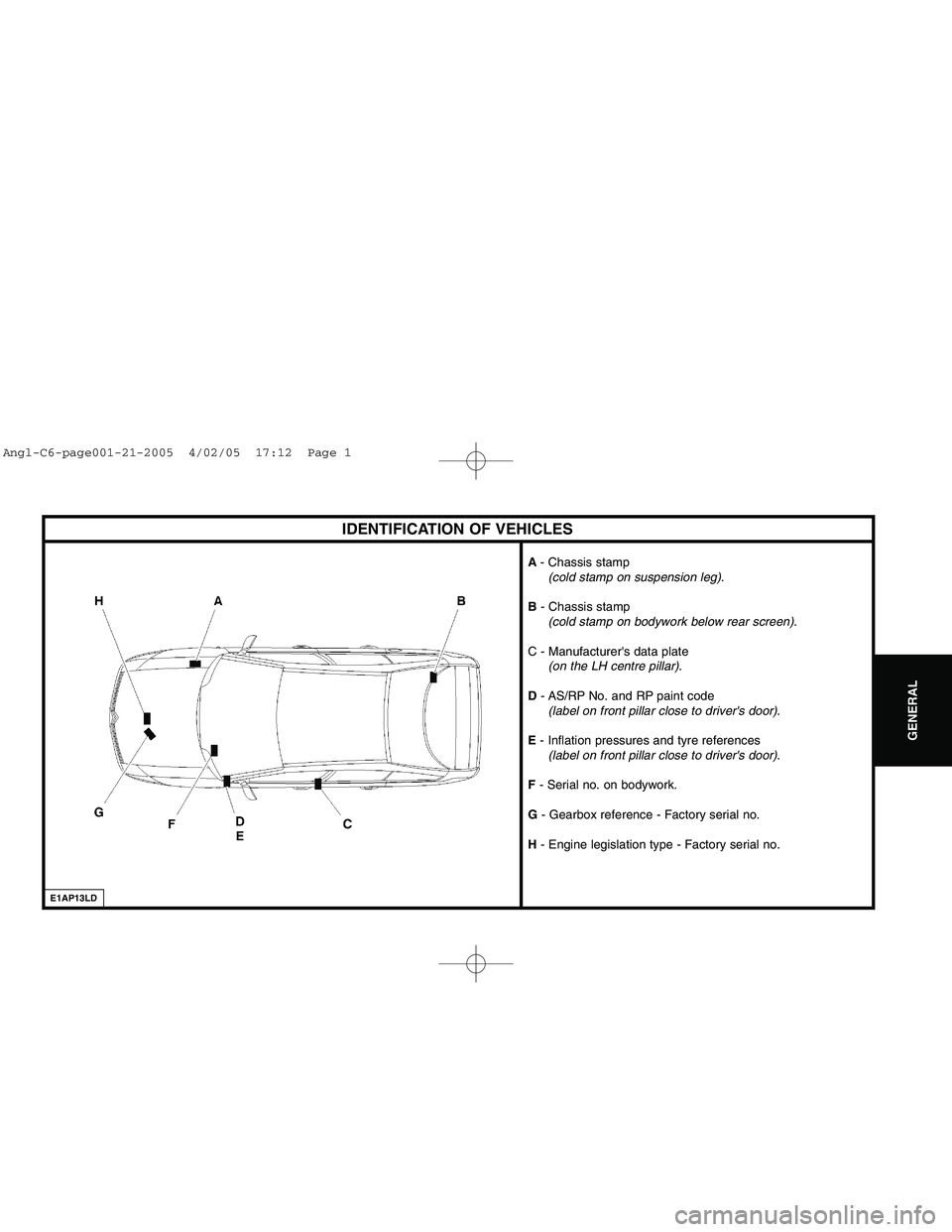
Downloaded from www.Manualslib.com manuals search engine IDENTIFICATION OF VEHICLES
E1AP13LD
A- Chassis stamp
(cold stamp on suspension leg).
B - Chassis stamp
(cold stamp on bodywork below rear screen).
C - Manufacturer's data plate
(on the LH centre pillar).
D - AS/RP No. and RP paint code
(label on front pillar close to driver's door).
E - Inflation pressures and tyre references
(label on front pillar close to driver's door).
F - Serial no. on bodywork.
G - Gearbox reference - Factory serial no.
H - Engine legislation type - Factory serial no.
GENERAL
Angl-C6-page001-21-2005 4/02/05 17:12 Page 1
Page 22 of 223
Downloaded from www.Manualslib.com manuals search engine Draining methods
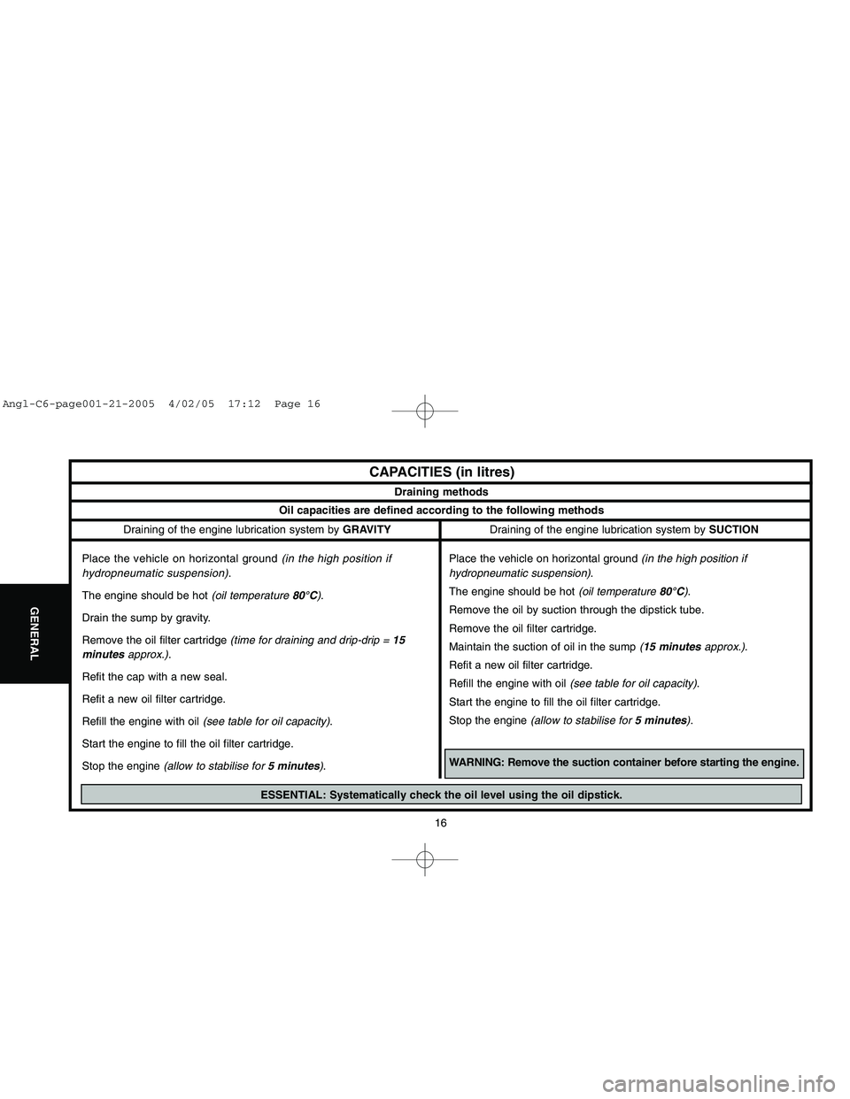
Oil capacities are defined according to the following methods
16
GENERAL
CAPACITIES (in litres)
Draining of the engine lubrication system by GRAVITY
Place the vehicle on horizontal ground (in the high position if
hydropneumatic suspension).
The engine should be hot (oil temperature 80°C).
Drain the sump by gravity.
Remove the oil filter cartridge (time for draining and drip-drip = 15
minutesapprox.).
Refit the cap with a new seal.
Refit a new oil filter cartridge.
Refill the engine with oil (see table for oil capacity).
Start the engine to fill the oil filter cartridge.
Stop the engine (allow to stabilise for 5 minutes).Draining of the engine lubrication system by SUCTION
Place the vehicle on horizontal ground (in the high position if
hydropneumatic suspension).
The engine should be hot (oil temperature 80°C).
Remove the oil by suction through the dipstick tube.
Remove the oil filter cartridge.
Maintain the suction of oil in the sump (15 minutesapprox.).
Refit a new oil filter cartridge.
Refill the engine with oil (see table for oil capacity).
Start the engine to fill the oil filter cartridge.
Stop the engine (allow to stabilise for 5 minutes).
WARNING: Remove the suction container before starting the engine.
ESSENTIAL: Systematically check the oil level using the oil dipstick.
Angl-C6-page001-21-2005 4/02/05 17:12 Page 16
Page 29 of 223
Downloaded from www.Manualslib.com manuals search engine 23
ENGINE
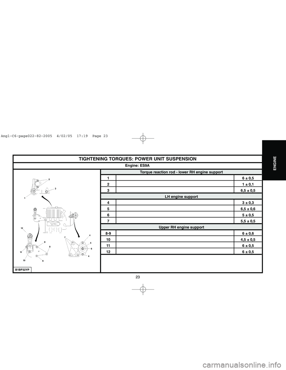
TIGHTENING TORQUES: POWER UNIT SUSPENSION
Torque reaction rod - lower RH engine support
16 ± 0,521 ± 0,136,5 ± 0,5
LH engine support
43 ± 0,356,5 ± 0,665 ± 0,575,5 ± 0,5
Upper RH engine support
8-96 ± 0,6104,5 ± 0,5116 ± 0,5126 ± 0,5
Engine: ES9A
B1BP32YP
Angl-C6-page022-82-2005 4/02/05 17:19 Page 23
Page 35 of 223
Downloaded from www.Manualslib.com manuals search engine 29
ENGINE
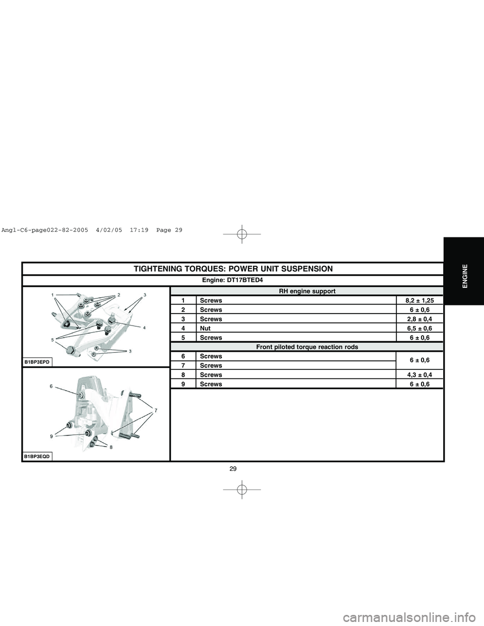
TIGHTENING TORQUES: POWER UNIT SUSPENSION
RH engine support
1 Screws 8,2 ± 1,252 Screws 6 ± 0,63 Screws 2,8 ± 0,44 Nut 6,5 ± 0,65 Screws 6 ± 0,6
Front piloted torque reaction rods
6 Screws
6 ± 0,6
7 Screws8 Screws 4,3 ± 0,49 Screws 6 ± 0,6Engine: DT17BTED4
B1BP3EPDB1BP3EQD
Angl-C6-page022-82-2005 4/02/05 17:19 Page 29
Page 36 of 223
Downloaded from www.Manualslib.com manuals search engine 30
ENGINE
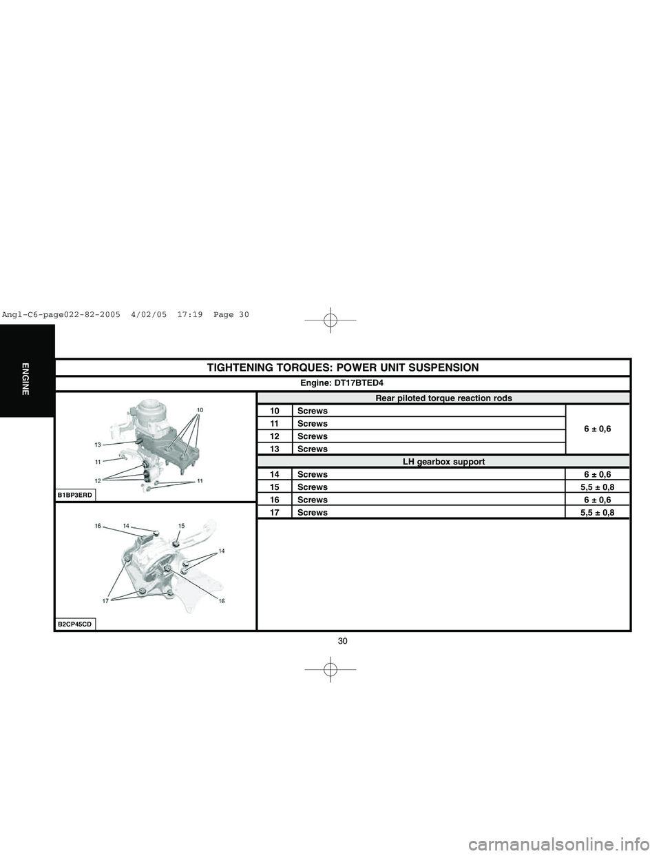
TIGHTENING TORQUES: POWER UNIT SUSPENSION
Rear piloted torque reaction rods
10 Screws
11 Screws
6 ± 0,6
12 Screws
13 Screws
LH gearbox support
14 Screws 6 ± 0,615 Screws 5,5 ± 0,816 Screws 6 ± 0,617 Screws 5,5 ± 0,8Engine: DT17BTED4
B2CP45CDB1BP3ERD
Angl-C6-page022-82-2005 4/02/05 17:19 Page 30
Page 37 of 223
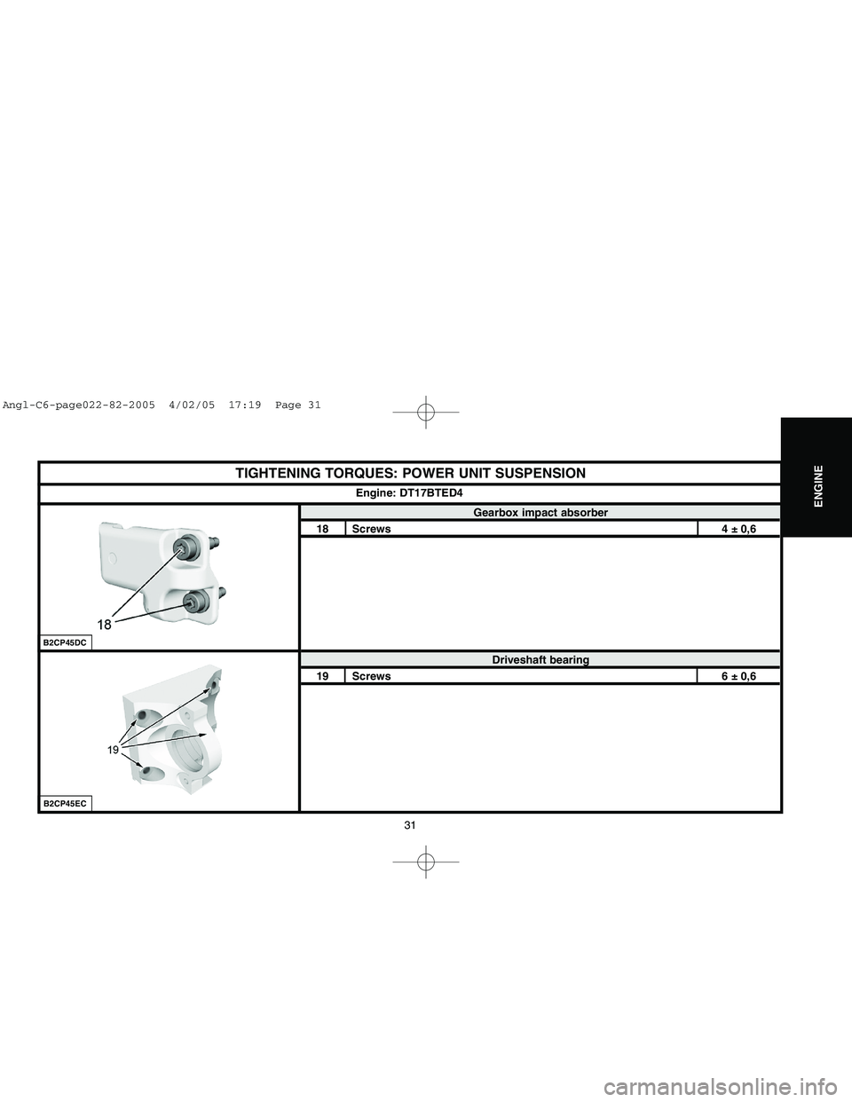
Downloaded from www.Manualslib.com manuals search engine 31
ENGINE
TIGHTENING TORQUES: POWER UNIT SUSPENSION
Gearbox impact absorber
18 Screws 4 ± 0,6
Driveshaft bearing
19 Screws 6 ± 0,6Engine: DT17BTED4
B2CP45ECB2CP45DC
Angl-C6-page022-82-2005 4/02/05 17:19 Page 31
Page 120 of 223
![CITROEN C6 2005 Owners Manual Downloaded from www.Manualslib.com manuals search engine 114
CLUTCH
GEARBOX
TRANSMISSION
DRAINING, FILLING AND TOPPING UP THE AM6 AUTOMATIC GEARBOX
Tool.
[1] Filling cylinder: (-).0340
Respect the sa CITROEN C6 2005 Owners Manual Downloaded from www.Manualslib.com manuals search engine 114
CLUTCH
GEARBOX
TRANSMISSION
DRAINING, FILLING AND TOPPING UP THE AM6 AUTOMATIC GEARBOX
Tool.
[1] Filling cylinder: (-).0340
Respect the sa](/img/9/57744/w960_57744-119.png)
Downloaded from www.Manualslib.com manuals search engine 114
CLUTCH
GEARBOX
TRANSMISSION
DRAINING, FILLING AND TOPPING UP THE AM6 AUTOMATIC GEARBOX
Tool.
[1] Filling cylinder: (-).0340
Respect the safety and cleanliness requirements.
Draining.
IMPERATIVE: Draining of the gearbox must be done with the oil hot (60°C minimum), in order to
ensure that the impurities in suspension in the oil are eliminated.
NOTE:Drainage is only partial, as the torque converter cannot be drained totally.
Raise the vehicle.
Remove:
- The oil level plug (2)by means of the Torx spanner.
- The drain plug (1)using a hexagonalspanner.
NOTE :Around 3 litresof oil should flow out.
Filling.
Fit the drain plug (1)(with a new seal).
Tighten the plug (1)to: 5 ± 1 mdaN.
Remove:
- The air filter housing.
- The oil filler plug (3).
Use tool [1].
B2CP3WZCB1BP317C
Angl-C6-page101-120-2005 4/02/05 17:25 Page 114