display CITROEN C6 DAG 2012 Handbook (in English)
[x] Cancel search | Manufacturer: CITROEN, Model Year: 2012, Model line: C6 DAG, Model: CITROEN C6 DAG 2012Pages: 216, PDF Size: 10.27 MB
Page 93 of 216

91
III
AUTOMATIC AIR CONDITIONING
To activate/deactivate
the air conditioningsystem
Press on the control"CLIM" to go into the "air condi-
tioning" mode. Then press button"OK" or on the control to bring up the "Air Conditioning menu" on the multifunction screen.
This menu allows you:To deactivate the air conditioning:"Cut aircon (A/C OFF)".
Press button"OK", or on the control, to validate
the offer to activate or deactivate the air conditioning.
The symbol "A/C OFF" displays on the
multifunction screen in the case of deactivation.
Note
:Your temperature adjustment value may not be reached and you risk having the windows misted up.
You can cancel deactivation of the air
conditioning, by pressing the control 1"AUTO".
•
-
-
To activate/deactivate the differentiation of the air conditioning adjustment on the driver's side and on
the passenger's side.
A
fter making your selection using the arrow keys,press on "OK"or on the control, to validate the offer to activate or deactivate the air conditioning.
Activation of this function makes the adjustments
on the passen
ger's side identical to those chosen
by the driver.Note:any manual action on button 2b or 3b returns you to the independent adjustments.
•
A press on the "Menu" button brings up the
"Main menu" for access to choices similar
to those offered by the"CLIM"button. See
"Multifunction display".
Page 95 of 216

93
III
The programmable heating sys-
tem operates independently of theengine.
With the engine off, it is used topreheat the engine cooling systemso as to have an optimum engine
operating temperature on starting.
The programmable heating systemis started using a long-range remotecontrol. It can be started immediatelyor programmed to start later.
In the event of a malfunction of
the programmable heating sys-tem, contact a CITROËN dealer pg gy
or a qualifi ed workshop.
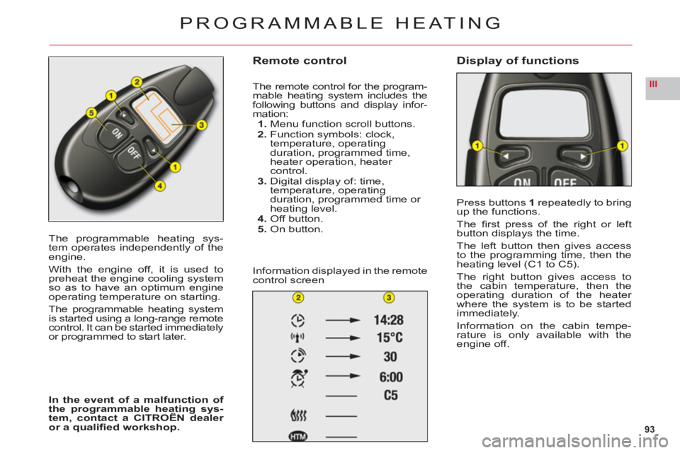
Remote control
The remote control for the program-
mable heating system includes the following buttons and display infor-
mation:1. Menu function scroll buttons.
2. Function symbols: clock,
temperature, operating
duration, programmed time, heater operation, heater control.3. Digital display of: time,
temperature, operating
duration, programmed time or heating level.4.Off button.5. On button.
In
formation displayed in the remote control screen
Display of functions
Press buttons1repeatedly to bringup the functions.
The fi rst press of the ri
ght or leftbutton displays the time.
The left button then
gives access
to the programming time, then theheating level (C1 to C5).
The right button gives access to
the cabin temperature, then the
operating duration of the heater
where the system is to be startedimmediately.
In
formation on the cabin tempe-rature is only available with theengine off.
PROGRAMMABLE HEATING
Page 96 of 216

94
III
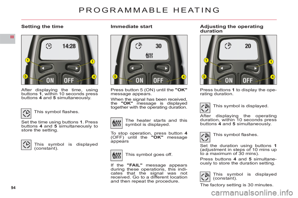
Setting the timeImmediate startAdjusting the operating duration
After displaying the time, usingbuttons1, within 10 seconds pressbuttons4and5 simultaneously.Press button 5
(ON) until the "OK"
message appears.
When the si
gnal has been received,
the "OK" message is displayed
together with the operating duration.
Press buttons1 to display the ope-rating duration.
PROGRAMMABLE HEATING
This symbol fl ashes.
Set the time using buttons 1. Pressbuttons4and 5 simultaneously tostore the setting.
This symbol is displayed (constant).
The heater starts and this
symbol is displayed.
To stop operation, press button
4(OFF) until the "OK"message
appears
This s
ymbol goes off.
I
f the"FAIL" message appears
during these operations, this indi-cates that the signal was not
received. Go to a different location
and then repeat the procedure.This s
ymbol is displayed.
After displaying the operating
duration, within 10 seconds pressbuttons 4and 5simultaneously.
This s
ymbol fl ashes.
Set the duration using buttons1(adjustment in steps of 10 mins up
to a maximum of 30 mins).
Press buttons 4 and 5 simultane-
ously to store the duration setting.
This symbol is displayed(constant).
The factor
y setting is 30 minutes.
Page 97 of 216

95
III
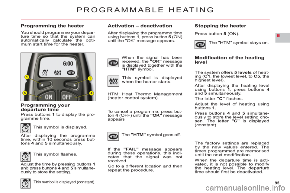
Programming the heaterActivation – deactivation Stopping the heater
You should programme your depar-
ture time so that the system can
automatically calculate the opti-mum start time for the heater.
Programming your departure time
The "HTM" symbol stays on.
PROGRAMMABLE HEATING
Press buttons 1to display the pro-
gramme time.
This symbol is displayed.
After displaying the programme
time, within 10 seconds press but-
t
ons 4 and 5 simultaneously.
This s
ymbol fl ashes.
Adjust the time by pressing buttons 1and press buttons 4and 45simultane-
ously to store the setting.
This symbol is displayed (constant).
When the signal has been received, the "OK"message
is displayed together with the
"HTM" symbol.
This symbol is displayed
when the heater starts.
After displaying the programme time using buttons 1, press button5 (ON) until the "OK" message appears.
HTM: Heat Thermo Management (heater control system).
To cancel a pro
gramme, press but-
ton 4 (OFF) until the "OK" message appears
The"HTM"symbol goes off.
If th
e"FAIL" message appears
during these operations, this indi-cates that the signal was not
received.
Go to a different location and then
repeat the procedure.
Press button 5 (ON).
Modifi cation of the heating level
The system offers5 levels of heat-
ing (C1, the lowest level, toC5, thehighest level).
After displaying the heating levelusing buttons 1, press buttons4and5simultaneously.
The letter "C"fl ashes.
Adjust the level of heating usingbuttons1.
Press buttons4and 5 simultane-ously to store the level setting cho-sen. The letter "C"is displayed(constant).
The factory settings are replaced
by the new values entered. The
times programmed are memoriseduntil the next modifi cation.
When the de
parture time is acti-
vated, it is not possible to modifythe heating level. The departure
time should fi rst be deactivated.
Page 108 of 216

106
III
A
SUSPENSION WITH ELECTRONICALLY
CONTROLLED SPRINGING AND DAMPING
Active suspension with piloted
damping and fl exibility automati-cally and instantaneously adjusts
the dampers to your driving style,as well as to the condition of theroad surface, to achieve the maxi-mum comfort for you and your passengers, as well as improvedroadholding.
Normal mode: This functioning mode fi lters the unevenness of the road
surface with the suppleness of the damping to produce a superlative ride.
S
port mode: a press on buttonAgives you a suspension that is more adaptedAto a sporty style of driving. This functioning mode makes the damping fi rmer,for enhanced control of the vehicle body movements.
This s
ymbol is displayed on your instrument panel.
SIGNALLINGIn the standard situation, buttonA is not lit up by day, it only illuminates at night.
In sport mode, after
you press button A, the latter lights up in orange,
day or night.
The mode selected is conserved until the ignition is switched off.
•
•
Page 109 of 216

107
III
GROUND CLEARANCE ADJUSTMENT
Position changes may only bemade when the engine is running.
The ground clearance is adjusted
automatically. You can however modify the vehicle height in cer-
tain specific cases.
To change the position
Press once on one of the adjust-ment controls. The change of position is indicated at the start
of the adjustment by:A message or
Temporary display of the initialposition with the symbol for the position requested.
Note: You are recommended toavoid any changing of position whileyou have your foot on the brake.
Viewing of the position of the
vehicle
On completion of the adjustmentyou see either a message or an
illustration of the position attained
by the vehicle, with the appropriatesymbol.
•
•
Maximum height
Changing a wheel.
Intermediate position
For an increased ground clearance.
For use on diffi cult roads when travel-ling at reduced speed, as well as oncarpark ramps.
Normal road position
Minimum height
To facilitate loading or unloadng the
vehicle.
For workshop inspections.
Not to be used in normal drivin
g.
For your safety if you are operating underneath the vehicle,it is obligatory to support the vehicle with axle stands.
Display of the position requested confi rms the completion of the adjustment.
Page 110 of 216

108
III
GROUND CLEARANCE ADJUSTMENT
AUTOMATIC CORRECTION OF GROUND CLEARANCE
Your vehicle has active suspension with variable damping which is electronically controlled. This automatically regulates
the ground clearance according to the vehicle speed and the road surface conditions.
Limits on access to the positions
Maximum height:
Impossible if speed > 10 km/h (6 mph).
Intermediate position:
Impossible if speed > 40 km/h (24 mph).
Normal road position: Alwayspermitted.
Minimum height:
Impossible if speed > 10 km/h (6 mph).Note:If the speed authorised for
a particular position is exceeded,the vehicle reverts automatically tothe normal road position.
Signalling of a requestedposition not authorised
On the display:
The display indicates for a short
time, via a message or by hatching on the requested position, that the
adjustment is impossible.
The vehicle remains in the position
that is authorised and the display
confi rms this position.
Automatic variation of groundclearanceIf your speed exceeds
110 km/h (68 mph), on a good road, the ground clearance is lowered.The vehicle reverts to the normal road position if the
road deteriorates or if your speed comes below 90 km/h(56 mph).
When the vehicle is stationary the ground clearance is lowered to the parking position.
•
•
Page 117 of 216

115
IIIABC
FRONT ARMREST
The armrest gives you extra com-
fort in your driving position.
To optimise
your driving position,lift the control B and push the arm-rest forwards.
Th
e armrest returns to its initialposition when you push it rear-
wards.
Storage areas
Two formatsof storage are avail-able:To have bigstorage in the
armrest, lift the controlC.For smallstorage in the
armrest, lift the controlA.
•
•
Ventilation of the bigstorage in the front armrest
The armrest has aventilation
duct for the big storage.
This benefi ts from the air condi-
tioning at a temperature identical
to the setting for the front of the cabin area. To adjust the air condi-
tioning fl ow, see "Rear automatic
air conditioning".
The ventilation duct canbe blocked manually.
INTERIOR COMFORT
USB SOCKET
This connection unit, consisting of
a JACK plug and/or a USB port,
is located in the front armrest.
You can connect portable equipmentsuch as an iPod®or a USB key.®
It reads audio fi le formats (mp3,
ogg, wma, wav, etc.) that it trans-mits to your audio system and areheard through the vehicle's loud-speakers.
Yo u can control these fi les with
the audio system’s steering wheel
or dashboard controls and displaythem on the multifunction screen.
Portable equipment can be rechargedwhile it is being used.
Page 127 of 216

125
IV
STARTING THE ENGINE AFTER DISCONNECTING AND RECONNECTING THE BATTERY
1. Turn the ignition key.2. Wait approximately 1 minute before operating the starter in order to allow the electronic systems to re-initialise.
After the battery has been disconnected for a lengthy period of time, it may be necessary to re-initialise the followingfunctions:The anti-pinch on the windows.
The anti-pinch on the sun roof.
The multifunction display parameters (date, time, language, units of distance and of temperature).
Th
e Radio stations.
The NaviDrive.
See the NaviDrive chapter.
IMPORTANT
In the event of a battery failure, and if the boot is closed, it is then necessary to feed an electrical supply to your
vehicle. See following page.
•
••
•
•
12 V BATTERY
Page 131 of 216

129
IV
TABLE OF FUSES
Ref.RatingFunction
F1––
F2––
F 35 AAirbags
F 410 ABraking system – Active bonnet – Cruise contol/speed limiter – Photochromic rear view mirror – Diagnostic socket –Multifunction screen inclination motorgygy
F 530 AFront window – Sun roof
F 630 ARear window
F 75 ASun visor lighting – Glove box lighting – Interior lamps – Rear cigar-lighter
F 820 AControls at the steering wheel – Display – Opening of windows (Micro-descent) – Alarm – Radio
F 930 AFront cigar-lighter
F 1015 ABoot relay unit – Trailer relay unit
F 1115 ASteering lock
F1215 ADriver’s and front passenger’s seat belt warning lamp – Opening of windows (Micro-descent) – Electric seats – Parkingassistance – Audio system JBL
F 135 AActive bonnet – Rain and brightness sensor – Windscreen wiper – Engine relay unit supply
F 1415 ALane Departure Warning System – Air conditioning – Instrument panel – Head-up display – Airbags – Bluetooth®(Hands-free kit) – BHI relaygyg
F 1530 ACentral locking – Child safety
F 16SHUNT–
F 1740 AVentilation
DASHBOARD FUSES (BOX C)