check engine Citroen CX 1974 1.G Owners Manual
[x] Cancel search | Manufacturer: CITROEN, Model Year: 1974, Model line: CX, Model: Citroen CX 1974 1.GPages: 394
Page 385 of 394
Downloaded from www.Manualslib.com manuals search engine 2 OPERATION NO MA. 841-O : Adjmfing /he o’r,ors
II. ADJUSTING A REAR DOOR
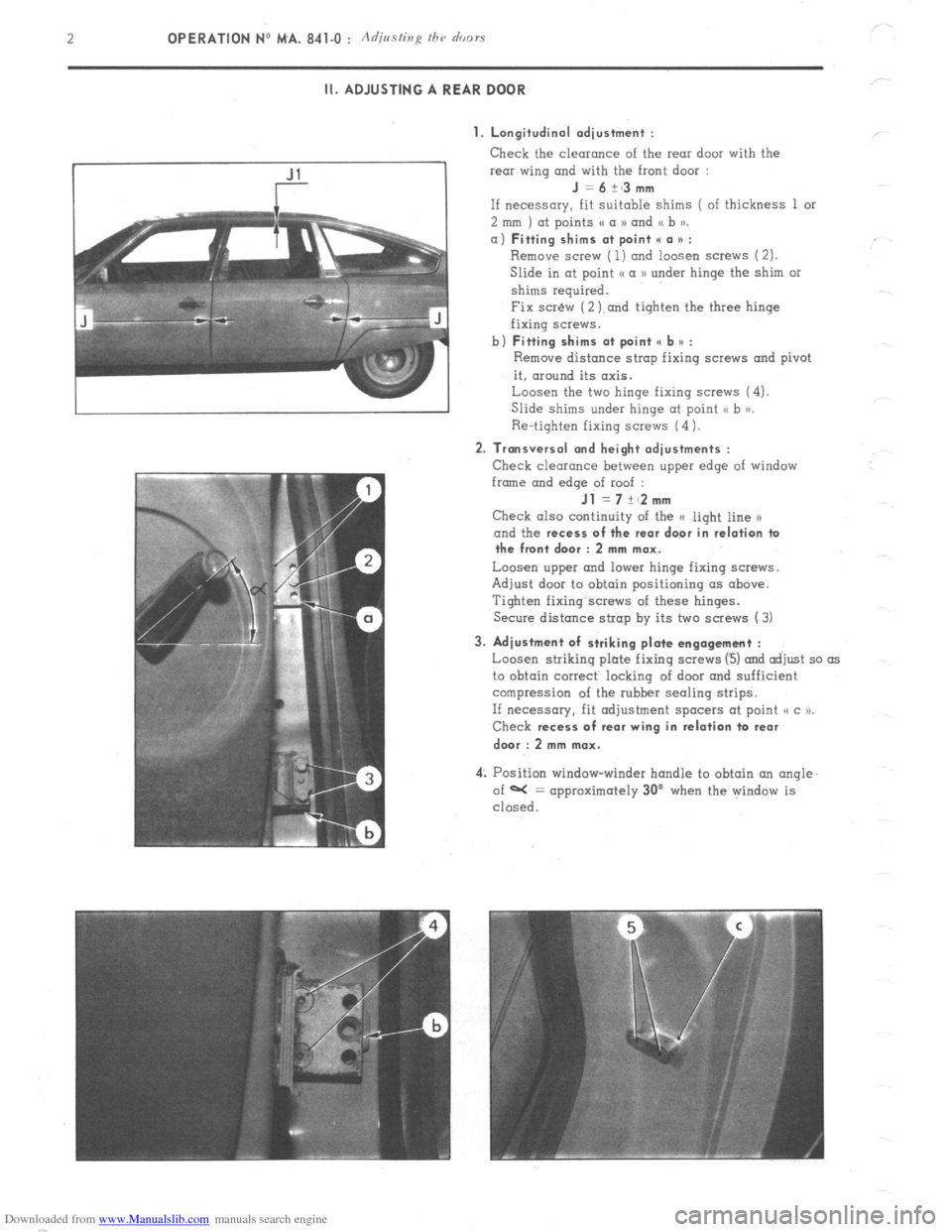
1. Longitudinal adjustment :
Check the clearonce of the rear door with the
rear wing and with the front door :
J =6+~3mm
If necessary, fit Suitable shims ( of thickness 1 or
2 mm ) at points (( a N and (( b )).
a) Fitting shims at point II a * :
Remove screw ( 1) ond loosen screws (2).
Slide in at point I< a D under hinge the shim or
shims required.
Fix scr&v (2 ).and tighten the three hinge
fixing screws.
b)
Fitting shims at point e b u :
Remove distance strop fixing screws and pivot
it, around its axis.
Loosen the two hinge fixing screws (4).
Slide shims under hinge at point <, b >j.
Re-tighten fixing screws (4 1.
2. Transversal and height adjustments :
Check clearance between upper edge of window
frmne and
edqe of roof :
Jl =7+~2mm
Check also continuity of the G light line x
and the recess
of the rear door in relation ta
the front door : 2 mm max.
Loosen upper and lower hinge fixing screws.
Adjust door to obtain positioning (IS above.
Tighten fixing screws of these hinges.
Secure distance strap by its two screws (3)
3. Adjustment of striking plate engagement :
Loosen striking plate fixing screws (3) and adjust so as
to obtain correct locking of door and sufficient
compression of the rubber sealing strips.
If necessary, fit adjustment spacers at point o c u.
Check recess
of rear wing in relation ta rear
dwr : 2 mm max.
4: Position window-winder handle to obtain an angle.
of W = approximately 30’ when the window is
closed.
Page 389 of 394
Downloaded from www.Manualslib.com manuals search engine OPERATION No MA. 961-O : C/ 3fc ztzg and repairing a war winabzc’ hrating elcmcnt k’ Op. MA. 961-O 1
I. CHECKING
Power of heating resistance :
S&Ions ., 140 to 160 watts at 13.5 1: 0.2 volts
Estates .,.,............: . . . . . . . .._.... . . . . . . . . . . . . . . . . . . . . . . . . . . . . . . . . . . . . . . . . . . . . . . . . . . . . . . . ~.. 130 to 150 watts at 13.5 t 0.2 volts
To check :he heating resistance of a rear window. measure
Either the current flowing in the resistance, using an ammeter connected in series to the supply lead of
the element. The current should be :
Saloons ,..., ., ,. ,. ,..,. ,,., ,,,., _, ,. .,., ..l_. 9.2 to 10.6 amps at 12 volts
Estates . . .., ,,..._.__.. .:_._ ._ . ..8 5 to 9.8 amps at 12 volts
Or the resistance using an ohmmeter. Resistance should be :
Saloons . . . . . . . . . . . . . . . . . . . . . . . . . . . . . . . . . j _..__.._....,. 1.1 to 1.3Q
Estates . .._...........,.,.,...,.....,..,..................................,,..,.,.,.,........,. 1 .2 to 1.4 !J
II. REPAIRING
1. Replacement of terminals : Tin that part of the terminal to be soldered. Solder it in the required location ( soldering iron ).
2. Repairing a section of the heating element : a) Obtain from the Replacement Parts Department :
- 1 Repair kit .,,..,,..,,.,.,.,.,,,.,.,,....,................,,,,,...,., ZC. 9 855 128 U
This M SECURIGLACE ))‘outfit includes :
- 1 Bottle of abrasive cleaning powder
- 1 Small bottle of conductive enamel
- 1 Tube of adhesive
- 1 Tube of hardener for adhesive
- 1 Small bottle of metallic powder
- 1 Roll of thick self-adhesive tape
- 1 Warning lamp for detecting cuts
- 1 Roll of self-adhesive tape for detecting cuts ( thermopaper )
- 1 Plastic spatula
- 1 Small glass plate ( for preparation of mixtures )
b)
Locating the cut : With the resistance fed as normal :
- Locate the defective resistance wire by sticking the adhesive detection tape at the centre of the rear
window ( interior side ) and on all resistance wires so that the tape is perpendicular to the latter.
The unbroken wires will turn the thermo-paper blue when they increase in temperature.
- Slide the two pointed probes of the warning lamp support on the cut wire. When the lamp lights up,
the pointed probes are on both sides of the break in the wire.
By slightly moving the probes along the length of the wire, the exact extent of the cut can be determined.
Page 390 of 394
Downloaded from www.Manualslib.com manuals search engine C) Preparing the rear window :
With the resistance switched off, clean the area to be treated with the powder contained in the bottle marked
(( Bimspulver )L
Spread this product on a small piece of cloth and rub.
Wipe off with a second clean cloth.
Place a strip, 25 mm long, of thick adhesive tape on each side of the resistance to mark out the width of the
resistance. The edges of the strip must be perfectly straight and clean so
as to avoid the possibility of a
cut during repair.
d
) Rep’ai r operation :
Zst part.
Empty the complete contents of the bottle of conductor enamel onto the glass plate. Mix thoroughly with the
spatula.
Apply the paste thus obtained on the area required,,filling the space between the two adhesive tapes.
Restrict the application of paste to the cut area.
Allow to dry at ambient temperature for approximately 15 minutes.
2nd Part
On the glass plate, prepare a small quantity of mixture composed of equal parts of UHV hardener and binding
agent.
Add to this paste an equal quantity of the metallic powder contained in the bottle marked (( Metallpulver )).
Mix well, using the spatula.
Apply the resulting paste on the conductor enamel deposit, overlapping on both sides by 10 mm, but with the
width still restricted by the strips of adhesive tape.
Thickness of the mixture should be equalized with the spatula, using the tape as a support.
Allow to dry for 1 l/2 hours at ambient temperature before removing the strips of adhesive tape.Move them aside
in a parallel direction to the surface of the rear window to avoid removing the applied film. Drying time can be
reduced by passing electric current through the resistance for half an hour.
NOTE : Wait for 24 to 48 hours before cleaning the inside of the rear window.
e) Checking :
The check can be carried out using the self-adhesive detecting tape.
Proceed as when locating the cut.
Page 391 of 394
Downloaded from www.Manualslib.com manuals search engine 1
SPECIAL i< T ,, TOOLS
MENTIONED IN VOLUME I OF MANUAL 818
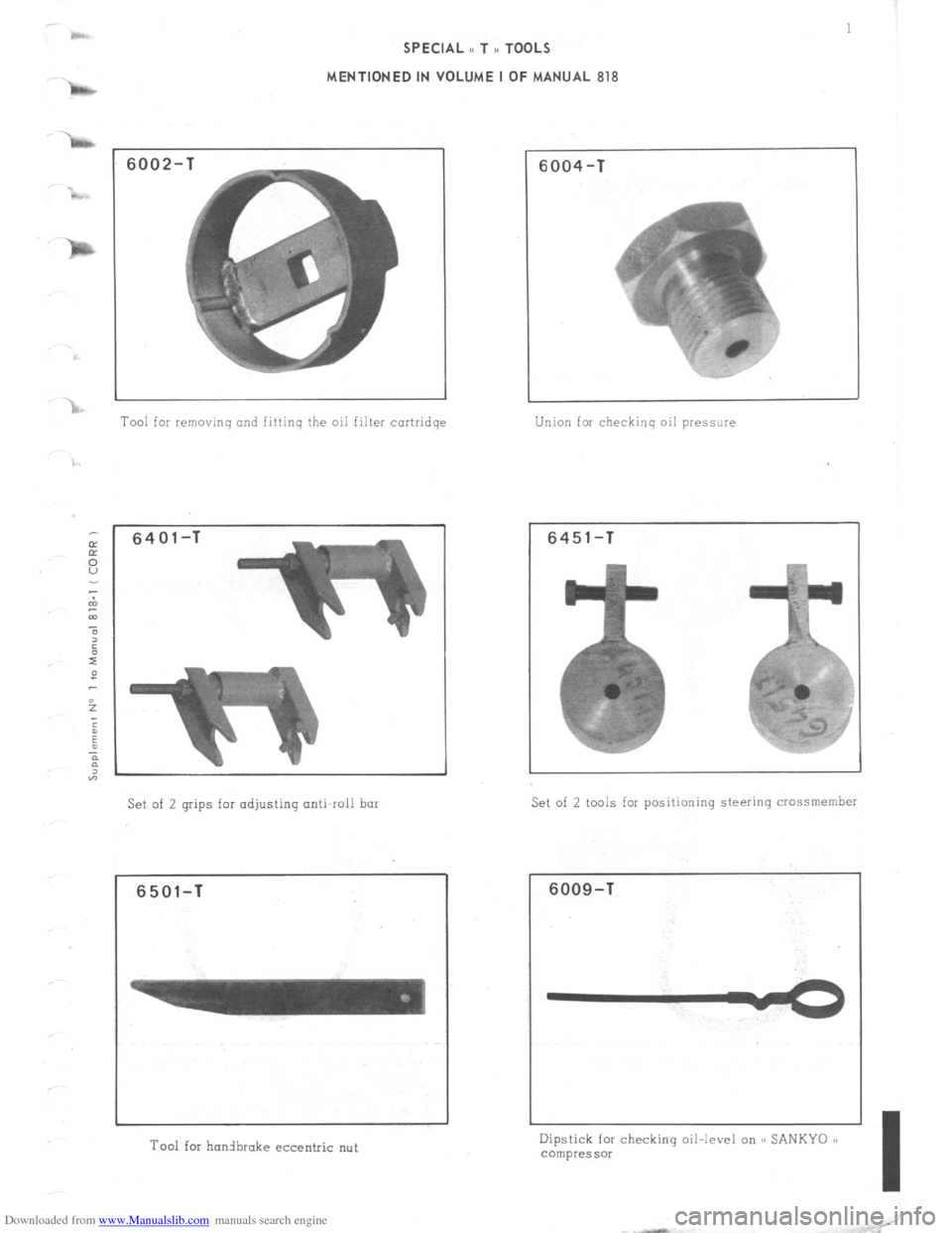
6002-
Tool for removing and fittinq the oil filter cortridqe
6401-T
Set of 2 grips for adjusting anti-roll bar
6501-T
Tool for honibrake eccentric nut
6004-T
Union for checking oil pressure
6451-T
Set of 2 tools for positioning steering crossmember
6009-T
Dipstick for checking oil-level on SC SANKYO 1)
compressor
I
Page 392 of 394
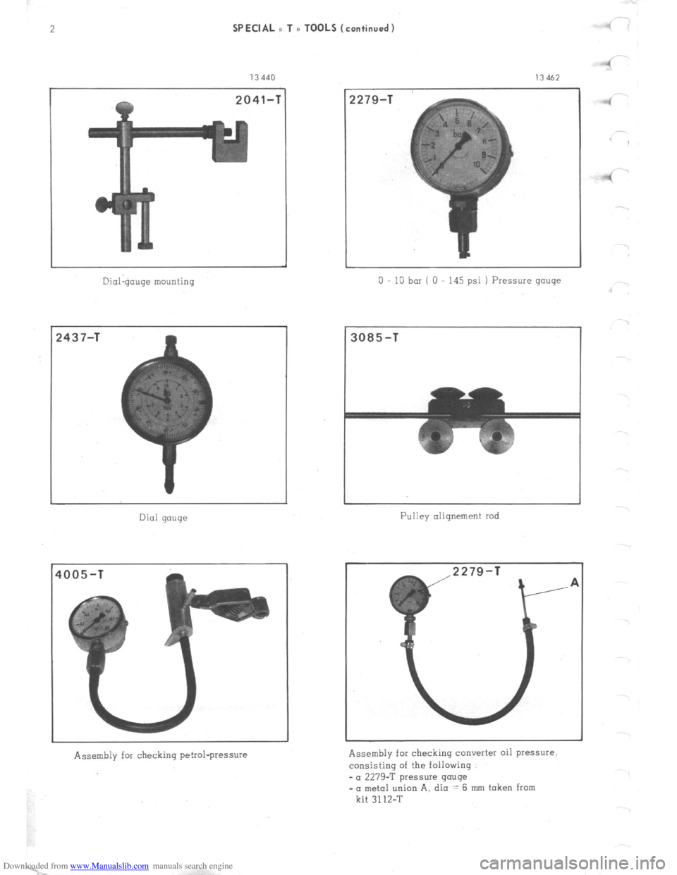
Downloaded from www.Manualslib.com manuals search engine 2 SPECIAL t TOOL
13440
2041-T
@ial$mge
mounting
!437-T Dial gauge
Assembly for checking petrol-pressure
(continued)
!279-1
13462
0 10 bar ( 0 145
psi ) Pressure gouge
3085-T
Pulley alignement rod
Assembly for checking converter oil pressure,
consisting of the following
-a 2279-T pressure gauge
- a metal union A, dia .= 6 mm taken from
kit 3112-T .4
4
.