check engine Citroen CX 1974 1.G Manual PDF
[x] Cancel search | Manufacturer: CITROEN, Model Year: 1974, Model line: CX, Model: Citroen CX 1974 1.GPages: 394
Page 283 of 394
Downloaded from www.Manualslib.com manuals search engine Op. MA. 453-O 1
I. BLEEDING THE BRAKES ON SALOON AND ESTATE VEHICLES ( 9/1976- )
A. FRONT BRAKE BLEEDING
NOTE : To avoid emulsifying the fluid
and the
consequent formation of air-pocket in the system,
the circuit should not be under pressure when this
operation is carried out.
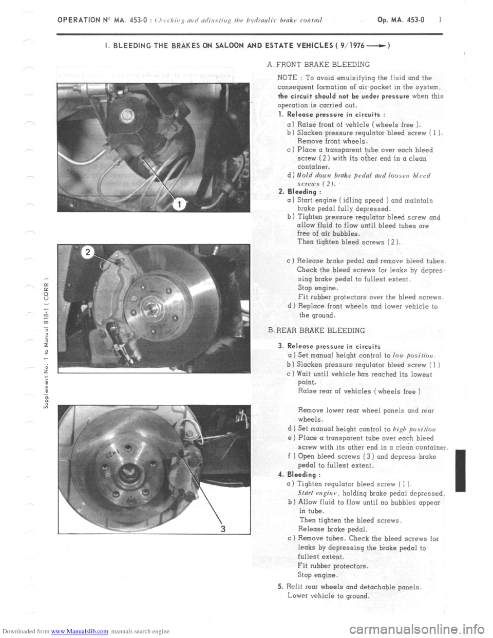
1. Release pressure in circuits :
a) Raise front of vehicle (wheels free 1.
b) Slacken pressure regulator bleed screw ( 1 ).
Remove front wheels.
c ) Place CI transparent tube over each bleed
screw (2 ) with its oiher end in CI clean
container.
d) Hold r/on,,,
brake pdnl ar,d loose,, blvcrl
*cr(Iws (2). 2. Bleeding :
(I 1 Start engin’e (idling speed 1 and maintain brake
pedal fully depressed.
b) Tighten pressure regulator bleed screw and
allow fluid to flow until bleed tubes ore
free of air bubbles.
Then tighten bleed screws (2 ).
c) Release broke pedal and remove bleed tubes.
Check the bleed screws for .leaks by depres-
sing brake pedal to fullest extent.
Stop engine.
Fit rubber protectors over the bleed screws.
d 1 Replace front wheels and lower vehicle to
the ground.
B. REAR BRAKE BLEEDING
3. Release pressure in circuits
a) Set monuol height control to lou posi/iou.
b 1 Slacken pressure regulator bleed screw ( 1 )
c) Wait until vehicle has reoched.its lowest
point.
Raise rear of vehicles (wheels free )
Remove lower rear wheel panels and rear
wheels.
d 1 Set manual height control to
hifih positior,
e ) Place Q transparent tube over each bleed
screw with its other end in (I cl&n container.
f ) Open bleed screws (3 ) and depress broke
pedal to fullest extent. 4. Bleeding :
(I) Tighten regulator bleed screw ( 1 1.
Slur/ w?@nr, holding broke pedal depressed.
b) Allow fluid to flow until no bubbles appear
in tube.
Then tighten the bleed screws.
Release brake pedal.
c ) Remove tubes. Check the bleed screws for
leaks by depressing the bloke pedal to
fullest extent. I
Fit rubber protectors.
Stop engine.
5. Refit rear wheels and detachable panels.
Lower vehicle to ground.
Page 284 of 394
Downloaded from www.Manualslib.com manuals search engine 2 OPERATION N” MA. 453-O : (./ ‘cc ,,,g md ndjaslisg I/w hsdrmlir hrnkr rev/m/
k.
II. BLEEDING THE BRAKES ON ESTA ,TE VEHICLES (- 0 ,970 )
A. BLEEDING THE FRONT BRAKES AND THE AIR
CHAMBER ( 1)
NOTE
This bleeding must be carried out with no
pressure in the system
in order to avoid any emul-
sifying of the liquid. and consequently the possible
formation of air bubbles in the system.
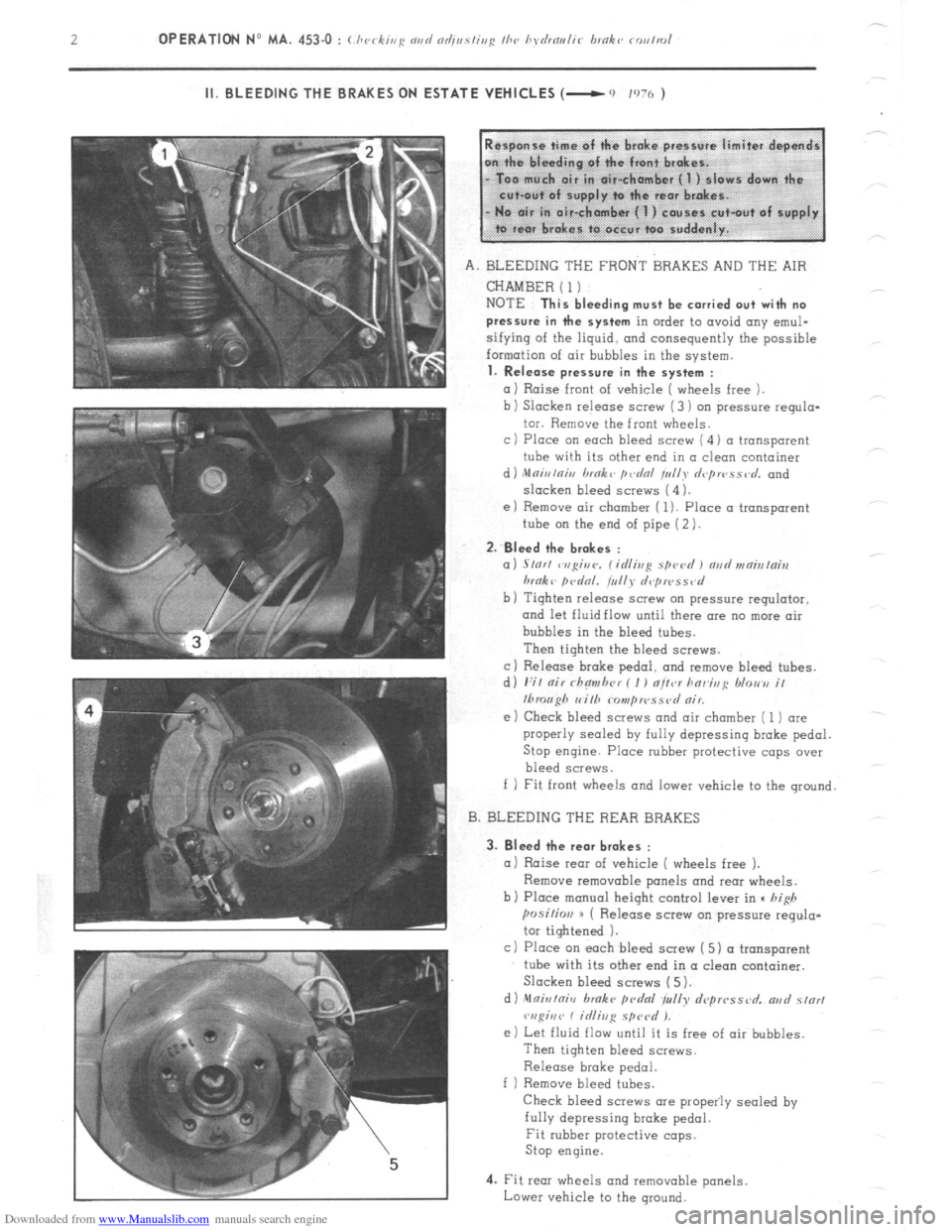
1. Release pressure in the system :
a 1 Raise front of vehicle ( wheels free ).
b ) Slacken release screw (3 ) on $ressure requlo-
tor. Remove the front wheels.
c 1 Place on each bleed screw ( 4 1 a transparent
tube wi!h its other end in a clean container
d ) ,Mnir,lnh, brnk L p&d /u//y d<~pwss,~d. and
slacken bleed screws (4 ).
e) Remove air chamber ( 1). Place a transparent
tube on the end of pipe (2 ).
2.
Bleed the br.kes :
a) S/or/ ~v,gir,c,. C id/ivg spevd I md vrnialni,r
hrnk L firdnl. tullr d,~pwss<~d
b) Tighten release screw on pressure regulator.
and let fluid flow until there are no more air
bubbles in the bleed tubes.
Then tighten the bleed screws.
c) Release broke pedo1, and remove bleed tubes.
d) I:;/ nir rhnmhrr ( I ) nltcr hnr~htg /dorm i/
Ibrouph I, i/h Nmp IPSS ?,I nir.
e ) Check bleed screws and air chamber ( 1) are
properly sealed
by fully depressing brake pedal.
Stop engine. Place rubber protective caps over
bleed screws.
f 1 Fit front wheels and lower vehicle to the ground
B. BLEEDING THE REAR BRAKES
3.
Bleed the rear brakes :
a 1 Raise rear of vehicle ( wheels free ).
Remove removable panels and rear wheels.
b) Place manual height control lever in c high
posi~im H ( Release screw on pressure regula-
tor tightened 1.
c) Place on each bleed screw ( 5) a transparent
tube with its other end in a clean container.
Slacken bleed screws (5).
d) nlfliuiniv broke pcdfll ~yrrlly depwssvd. ar,d s/or,
vspiuv C idiivg sprcd ).
e) Let fluid flow until it is free of air bubbles.
Then tighten bleed screws.
Release brake pedal.
f ) Remove bleed tubes.
Check bleed screws are propeily sealed by
fully depressing broke pedal.
Fit rubber protective cops.
Stop engine.
4. Fit rear wheels and removable panels
Lower vehicle to the ground.
Page 285 of 394
Downloaded from www.Manualslib.com manuals search engine OPERATION No MA. 453=0 : Ch J k’ ( c zng and adjjusfing thr hydraulk brake rontrol Op. MA. 453-O 3
III. CHECKING BRAKE PEDAL FREE PLAY
1 st Fitting 2nd Fitting
1 5 111 (I I /‘)7-t __t i%
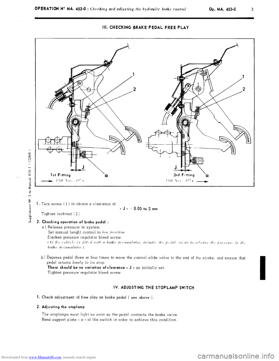
+ 1. Turn screw ( 1 ) to obtain a clearance of
s
E
(( J )) ~~ 0.05 to 3 mm
-ii Tighten lock-nut ( 2 ).
2 2. Ch k’ ec Ing operation of brake pedal :
a) Release pressure in system.
Set manual height control to /or! /~~.s\‘itio~/
Slacken pressure regulator bleed screw.
( I/ Ill<, I <~/liClC~ is /ill1 rl i, ill, N I~tYlk~~ n~-rllrlll,Inlo,~. nc/un/1 II?<, /I< r/al.
hnke nr c111uu/n/0,. ).
b) Depress pedal three or four times to move the control slide valve to the end of its stroke, and ensure that
pedal returns freely to its stop.
There should be no variation of clearance o J )) as initially set.
Tighten pressure regulator bleed screw.
IV. ADJUSTING THE STOPLAMP SWITCH
1.
Check adjustment of free play on brake pedal ( see above ).
2. Adiusting the stoplamp
The stoplamps must light as soon as the pedal contacts the brake valve.
Bend support plate u a )) of the switch in order to achieve this condition.
Page 286 of 394
Downloaded from www.Manualslib.com manuals search engine OPERATION No MA. 454-O : Lhcckiu~ avd adjnsfbrR fhe bandbrake op. MA. 454-u I CHECKING AND ADJUSTING THE HANDBRAKE
1.
Raise front of vehicle ( wheels free ).
Remove front wheels.
Release handbrake lever to maximum extent 2. Adjust eccentrics :
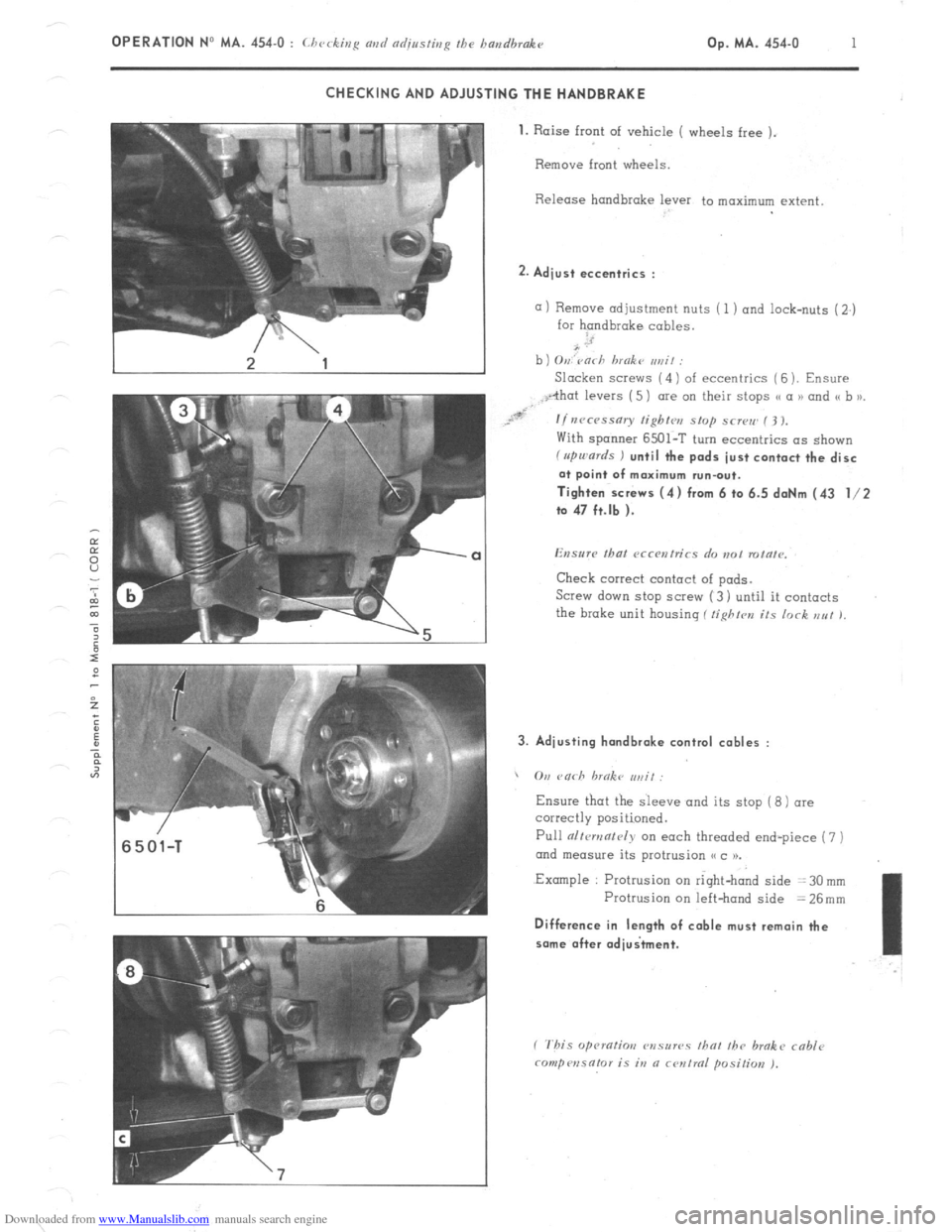
a) Remove adjustment nuts ( 1 ) and lock-nuts (2.)
for handbrake cables.
b ) O,,,‘varh hmokt~ ,,rzit :
Slacken SCI~WS (4) of eccentrics ( 6 ). Ensure
With spanner 6501-T turn eccentrics as shown f rrpu,ards ) until the pads just contact the disc
at point of maximum run-out.
Tighten screws (4) from 6 to 6.5 daNm (43 l/2
to 47 ft.lb ).
Check correct contact of pads.
Screw down stop SCI~W (3) until it contacts
the brake unit housing ( tighfrn its lock EN! 1, 3. Adjusting hondbrake control cables :
, On rnrh hrnkc ,,,, if:
Ensure
Pull alfcmnf~~iy on each threaded end-piece (7 )
ond measure its protrusion (< c 1).
.Example : Protrusion on right-hand side = 30 mm
Protrusion on left-hand side = 26mm Difference in length of cable must remain the
some after adiuitment.
Page 287 of 394
Downloaded from www.Manualslib.com manuals search engine OPERATION No MA. 454-O : Ch ec tzg and a&sting the handbrakc k’
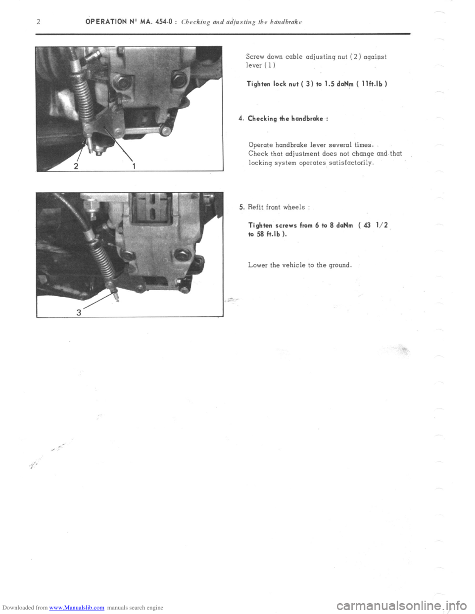
Screw down cable adjusting nut (2) against
lever ( 1) Tighten lock nut ( 3) to 1.5 doNm ( llft.lb)
4. Checking tie handbrake :
Operate handbrake lever several times.
Check that adjustment does not change and that
locking system operates satisfactorily.
5. Refit front wheels : Tighten screws from 6 to 8 daNm ( 43 l/2,
ta 58 ft.lb ).
Lower the vehicle to the ground.
Page 350 of 394

Downloaded from www.Manualslib.com manuals search engine OPERATION No MA. 530-00 : (./Jo).N~.I(,I.;sI~~-s I>/ I/I<> vfvctrir-nl c~NI/~~~I/~~~IIs.
Op. MA. 530-00 3
III. STARTER MOTORS.
ALL ENGINES
DUCELLIER 6236 AND PARIS-RHONE D 9 E 16 STARTERS
CHARACTERISTIC CURVES
daNm
0.5 - 5
0 =f N
?l!fBl 7
a3
2
Trrt rt-ul I I I I / I 1 0
? I s1
2 -I
2 ’ I I III I I I I
F
200 400 600 800 1 AMPS
2
1000 2000 3000 4000 N RPM ;
E
r:
z, CHECKING.
ON VEHICLE : Ensure that battery is fully charged, and measure the following :
a) Current consumed,( pinion locked ) ._... . . . . . . . . .: . . . . . . . . . . . . . . . . . . . . . . . . . . 440 A ( 6236 ) and 450 A ( D 9 E 1 6 )
b) Current consumed when starting ( at 20’ C ) . . . . . . . . . ,.......,........................... 150 to 170 A
c) Current consumed with no load ( starter removed ) ,.,.,.,. ..,.,. ,...,.,...,.....,.,.,.,.,.,. 50 A maximum
BENCH TEST
: Use a 12 V - 200/40 Ah fully charged battery.
MEASUREMENTS
. Average torque at 1000 rpm _ .................................................................
Corresponding current ._ ............................................................... ......
. Torque locked ............................ ........................ ........................ ............
Corresponding current ._ ........................... ...... ............ ......................
Voltage ..................................................... ...... ........................................
Maximum power ._ ........................................................... ..........................
Voltage ....................................................................................................
Current .............................................................................................
Torque ._ ................................................................................................... DUCELLIER PARIS-RHONE
6236 D9E16
1.85 daNm (6 1 ft.lb)
300 A
.15 daNm (1.08 ft.lb)
440 A.
7.4 v
965 W
9.4 v
240 A
1.6 daNm ( 4.3 ft.lb) 1.83 daNm (6 ft.lb)
270 A
1.155daNm (1.12 ft.lb)
,450 A
7v
920 w
9v
215 A
0.6 daNm (4.3 ft.lb)
Page 353 of 394
Downloaded from www.Manualslib.com manuals search engine OPERATION N9 MA. 530.0 : Cbcc-king thv c)lcctrical com&r~cr~ts Op. MA. 530.0 1
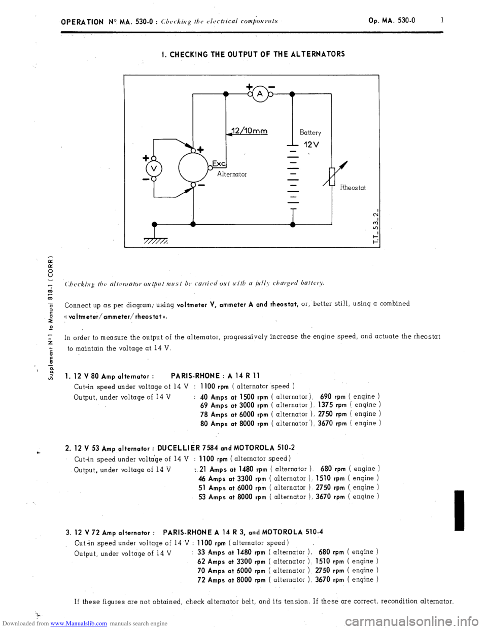
I. CHECKING THE OUTPUT OF THE ALTERNATORS
7
co
co
5 or, better still, using a combined
z Connect up as per diagram; using
voltmeter V, ammeter A and rheostat,
,iiJ (( voItmeter/ammeter/rheostat~~.
2
-
2 In order to measure the output of the alternator, progressively increase the engine speed, and actuate the rheostat
5 to maintain the voltage at 14 V.
E
-c
9
*
1. 12 V 80 Amp alternator : PARIS-RHONE : A 14 R 11
Cut-in speed under voltage of 14 V : 1100 rpm ( alternator speed )
Output, under voltage of 14 V :
40 Amps at 1500 rpm ( alternator j. 690 rpm ( engine )
69 Amps at 3000 rpm ( alternator ), 1375 rpm ( engine )
78 Amps at 6000 rpm ( alternator ). 2750 rpm ( engine )
80 Amps at 8000 rpm ( alternator ‘), 3670 rpm ( engine )
F 2. 12 V 53 Amp alternator : DUCELLIER 7584 and MOTOROLA 510-2 Cut-in speed under voltage of 14 V : 1100 rpm ( alternator speed)
Output, under voltage of 14 V
z.21 Amps at 1480 rpm ( alternator 1 680 rpm ( engine )
46 Amps at 3300 rpm ( alternator ): 1510 rpm ( engine )
51 Amps at 6000 rpk ( alternator ) 2750 rpm (engine )
53 Amps at 8000 rpm ( alternator ). 3670 rpm ( engine )
3. 12 V 72 Amp alternator : PARIS-RHONE A 14 R 3, and MOTOROLA 510-4
Cut-in speed under voltage of 14 V : 1100 rpm ( alternator speed)
Output, under voltage of 14 V : 33
Amps at 1480 rpm ( alternator ). 680 rpm ( engine )
62 Amps at 3300 rpm ( alternator 1 1510 rpm ( engine )
70 Amps at 6000 rpm
( alternator ) 2750 rpm ( engine )
72 Amps at 8000 rpm ( alternator 1. 3670 rpm ( engine )
If these figures are not obtained, check alternator belt, and its tension. If these are correct, recondition alternator
Page 354 of 394
Downloaded from www.Manualslib.com manuals search engine Il. CHECKING THE REGULATED TENSION OF THE REGULATORS
CHARACTERISTICS
- Two-stage voltage regulator : Ref : DUCELLIER 8379 A, PARIS-RHONE AYC 2114 and AYC 2117.
SEV-MARCHAL F. 14 V 72717102
These voltage regulators determine the intensity of the current in the alternator inductor in order to maintain a
constant regulated voltage at the battery terminals.
, CHECKING THE REGULATED VOLTAGE
(.‘hcckitlg ti7c rc~~~~~l~tc~cl u~IIcl,~c~ mris t 170 rnrric,rl out u,ith a lrilly darg~~rl hnttcry.
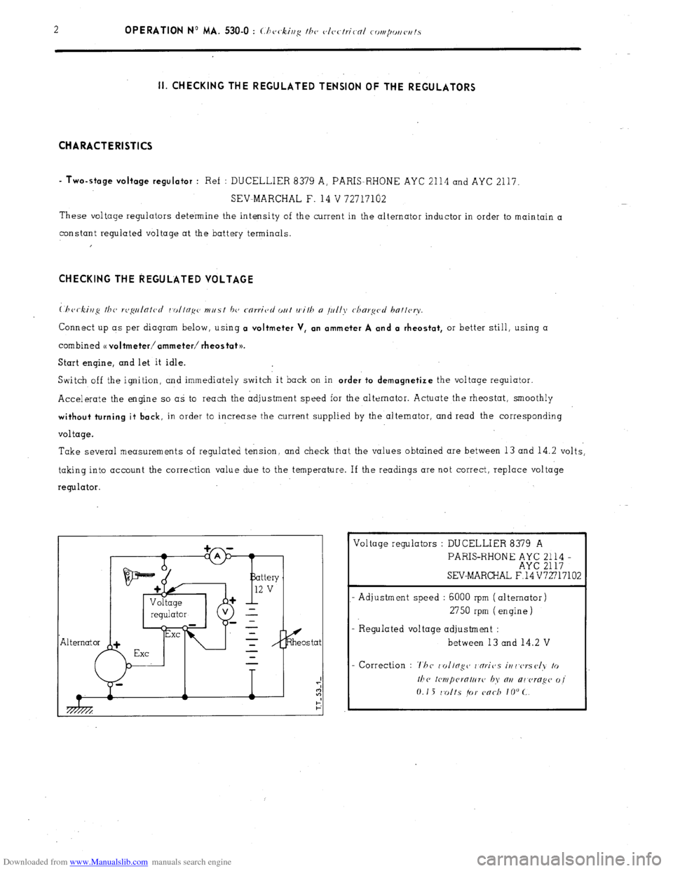
Connect up as per diagram below, using a voltmeter V, an ammeter A and a rheostat, or better still, using a
combined
o voltmeter/ammeter/ rheostat )).
Start engine, and let it idle.
Switch off the ignition, and immediately switch it back on in
order to demagnetize the voltage regulator.
Accelerate the engine so as to reach the adjustment speed for the alternator. Actuate the rheostat, smoothly
without turning it back, in order to increase the current supplied by the alternator, and read the corresponding
voltage.
Take several measurements of regulated tension, and check that the values obtained are between 13 and 14.2 volts,
taking into account the correction value due to the temperature. If the readings are not correct, replace voltage
regulator.
Exe Voltage regulators : DUCELLIER 8379 A
PARIS-RHONE ;;E ;;;; -
SEV-MARCHAL F.14 V72717102
- Adjustment speed : 6000 rpm (alternator)
2750 rpm (engine)
- R egulated voltage adjustment :
between 13 and 14.2 V
Page 355 of 394
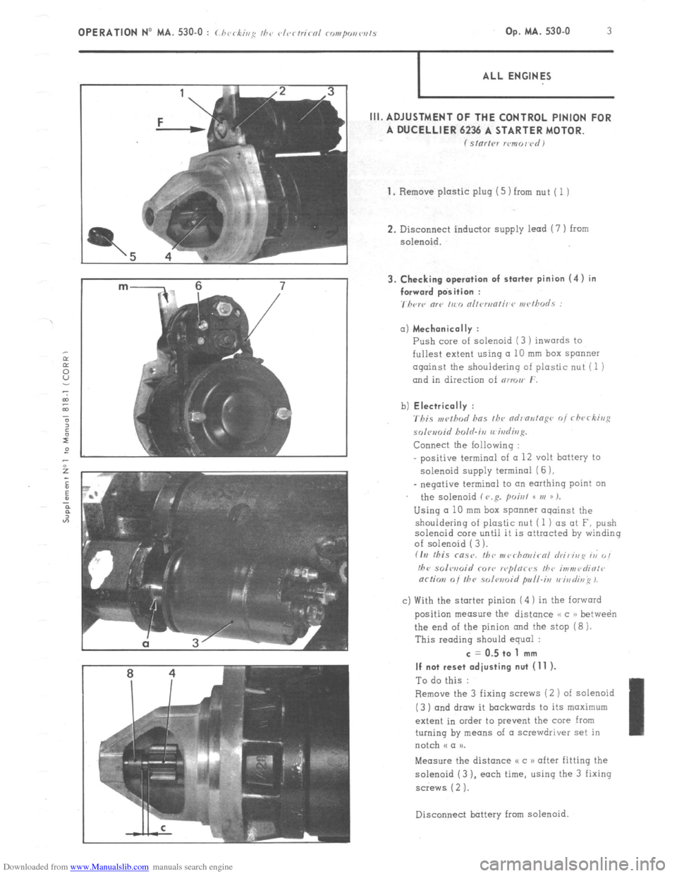
Downloaded from www.Manualslib.com manuals search engine m- 6 7 3. Checking operation of starter pinion (4) in
/ forward position :
7hcrc “lP ,,c,, nllrn,nli,~r~ rn<~~h”LS : OPERATION No MA. 530-O : (./ 1< ‘ ,,,g II,‘, vl<~rtricnl rompo,,w,ls , -k’ Op. MA. 530-O 3
ALL ENGINES
III. ADJUSTMENT OF THE CONTROL PINION FOR
A DUCELLIER 6236 A STARTER MOTOR.
f Sl”l’,Pl xmor~rdI
1.
Remove plastic plug (5) from nut ( 1 )
2. Disconnect inductor supply lead (7 ) from
solenoid. a) Mechanically :
Push core of solenoid (3 ) inwards to
fullest extent using a 10 mm box spanner
against the shouldering of plastic nut (1 )
and in direction of nrmw r.
b) Electrically :
'rbis ,w!hod has fh~ ndr'ontopr~ of rfwrking
solomid holrl.irz rrirdivg.
Connect the Iollowing :
positive terminal of (I 12 volt battery to
solenoid supply termina1 (6 ),
_ negative terminal to an earthing point on
the solenoid f V.R. poisl GC VI )) %
Using a 10 mm box spanner oqainst the
shouldering of plastic nut (1 ) as at F, push
solenoid core until it is attracted by winding
of solenoid ( 3 ).
fIrI this msr. fbc nr~~rhn~~irnl hi, irip ri 0,
!hc solwoid COY<, r<~plor<~s I/?<, i,,?“,<~diOl<~
or/ion 0i the solwoid pull-i,, vi,,di~~ 1.
c) With the starter pinion (4 ) in the forward
position measure the distance /, c )r betwe&
the end of the pinion and the stop (8 ).
This reading should equal : c = 0.5 to 1 mm
If not reset adjusting nut (11 ).
To do this :
Remove the 3 fixing saews (2 ) of solenoid
(3 ) and draw it backwards to its maximum
extent in order to prevent the core from
turning by means of a screwdriver set in
notch N a u.
Measure the distance I< c 1) after fitting the
solenoid (3 ). each time, using the 3 fixing
screws ( 2 ‘J.
Disconnect battery
from solenoid.
Page 356 of 394

Downloaded from www.Manualslib.com manuals search engine 4 OPERATION No MA. 530-O : Cbrckivp thr elrrfriral romponrwts 4. Checking starter pinion (4) in the free position :
With
the solenoid (3 ) mounted on starter, the
starter pinion (4 ) is normaHy in free position
Measure the distance o d n between the flange
of the starter nose at u b H in the bore
of the
motor housing and the extremity of the starter
pinion.
This reading should
equal :
d = 30.5 mm maxi
If not, recondition the starter.
Connect the inductor supply wire (I I
Refit plastic plug (5.1 (see page 3 1.