stop start Citroen CX 1974 1.G User Guide
[x] Cancel search | Manufacturer: CITROEN, Model Year: 1974, Model line: CX, Model: Citroen CX 1974 1.GPages: 394
Page 292 of 394
Downloaded from www.Manualslib.com manuals search engine OPERATION No MA. 510-00 : \m//l‘!yc~tl/ <‘,/I 0 t Ih<’ <‘It,< Ir.itnl iusrtlllnliritt Op. MA. 510-00 3
f 0 lO7i-l,‘1975 )
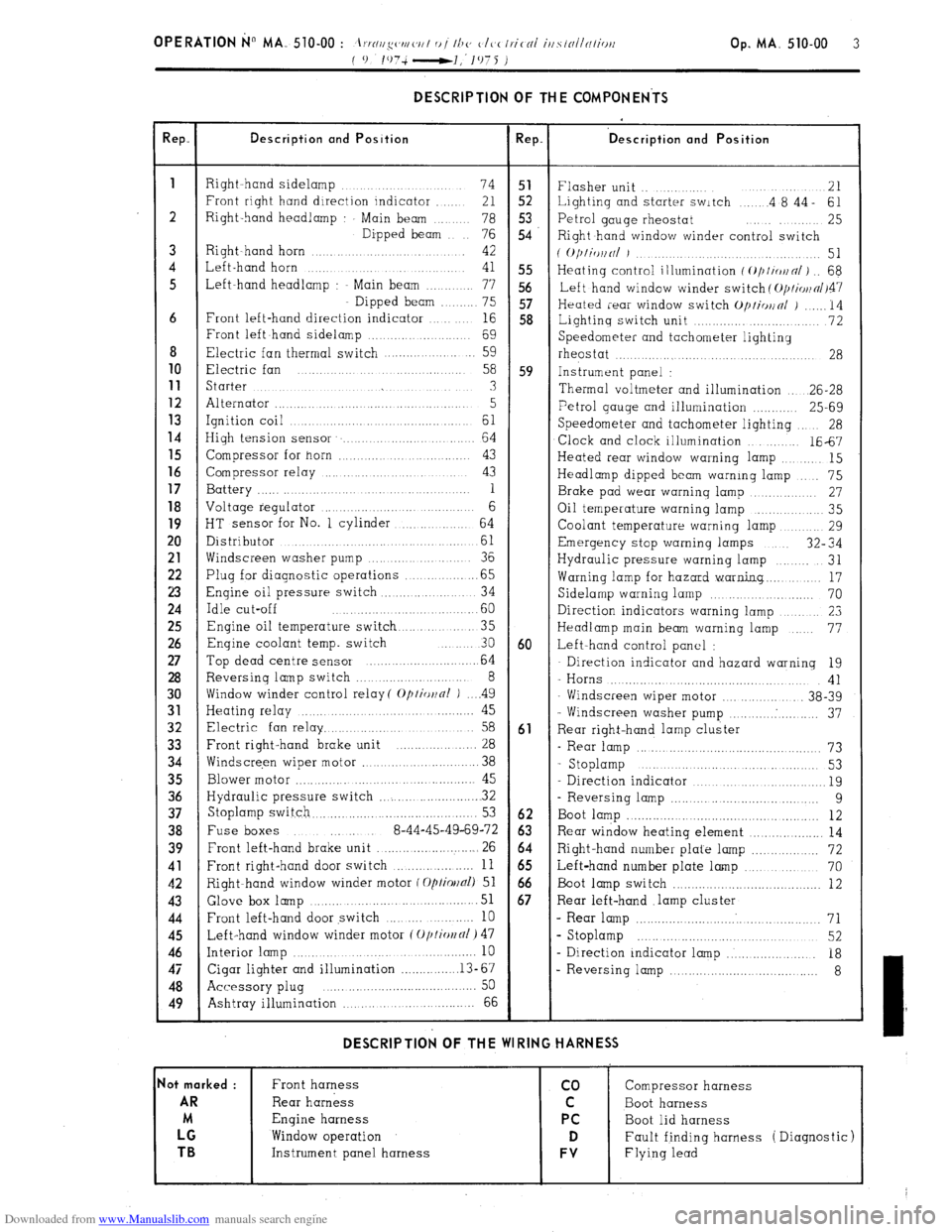
DESCRIPTION OF THE COMPONENTS
!ep. Description and Position Rep. ‘D escription and Position
1
Right hand sidelamp ...... 74 51
Flasher unit .. ....... 21
Front right hand direction indicator ..... 21 52 Lighting and starter switch .... .4 8’44- 61
2 Right-hand headlamp Main beam .. 78 5.3
76 54 Petrol gauge rheostat ........ 25
Dipped beam
Right hand window winder control switch
3 Right~hand horn ............ 42
( O/)liWlNl J ................. 51
4 Left-hand horn ...
41 55 Heating control illumination f ~///io~n/) .. 68
5 Left-hand headlamp : Main beam ....... 77 56
Left hand window winder switch ( O/JI~OII~/~~~
Dipped beam ...... 75 57
Heated rear window switch Op/io~nl j ...... 14
6 Front left-hand direction indicator ... 16 58
Lightinq switch unit ............. ........... 72
Front left hand sidelamp ................. 69
Speedometer and tachometer lighting
8 Electric fan thermal switch .................. 59
rheostat ....... ...... .................... 28 10
Electric fan .......
58 59 Instrument panel : 11
Starter ...... ... .............. .......... 3
Thermal voltmeter and illumination .. 26-28 12
Alternator ............................ ........ 5 13 Petrol gauge and illumination ............ 25-69
Ignition coil ... ......... .............. 61 14
Speedometer and tachometer lighting 28
High tension sensor ....................... 64
Clock and clock illumination ....... 1667 15
Compressor for horn ............ ..... ...... 43
Heated rear window warning lamp ....... 15 16
Compressor relay ................... ..... 43
Headlamp dipped beam warning lamp ... 75 17
Battery ............. .... .. 1
Brake pad wear warning lamp .......... 27 18
Voltage regulator ......................... 6
Oil temperature warning lamp ............ 35
19
HT sensor for No. 1 cylinder ........... 64
Coolant temperature warning lamp ....... 29 20
Distributor ..................... ...........
61 Emergency stop warning lamps 32” 34
21
Windscreen washer pump ............. 36
Hydraulic pressure warning lamp ...... 31 22
Plug for diagnostic operations ............. .65
Warning lamp for hazard warning.. ...... 17 23
Engine oil pressure switch .............. .. 34
Sidelamp warning lamp ................... 70 24
Idle cut-off ....................... .60
Direction indicators warning lamp ........... 23 25
Engine oil temperature switch ........... 35
Headlamp main beam warning lamp ... 77 26
Enqine coolant temp. switch ... 30 60 Left-hand control panel : 27
Top dead centre sensor ........................ 64 Direction indicator and hazard warning 19 28
Reversing lamp switch ........................ 8
- Horns .................................... 41 30
Window winder control relay( Optior~nl ) .. ..4 9
Windscreen wiper motor ............... 38-39 31
Heating relay ............ ..................... 45
- Windscreen washer pump .......... . .......... 37 32
Electric fan relay ................................ 58 61
Rear right-hand lamp cluster 33
Front right-hand brake unit ................. 28
- Rear lamp ............................................... 73 34
Windscre,en wiper motor ........................ 38
- Stoplamp ............. .....
............ 53
35
Blower motor ............ .............................. 45
Direction indicator ................................... 19 36
Hydraulic pressure switch ...................... . 32
- Reversing lamp ..................................... 9 37
Stoplamp switch.. ......................................... 53 62
Boot lamp ................................................. 12 38
Fuse boxes ..... 8-44-45-49-69-72 63 Rear window heating element ................... 14 39
Front left-hand brake unit .......................... 26 64
Right-hand number plate lamp ................. 72 41
Front right-hand door switch ................... 11 65
Left-hand number plate lamp ................... 70 42
Right-hand window winder motor f Optiollal) 51 66
Boot lamp switch ........................................ 12 43 Glove box
lamp ...................................... 51 67 Rear left-hand .lamp cluster 44
Front left-hand door switch ........ .......... 10 - Rear lamp ................................................ 71 45
Left-hand window winder motor (Oplio~fll) 47 s Stoplamp ........................................... 52 46
Interior lamp ................................................. 10
- Direction indicator lamp ..................... 18 47
Cigar lighter and illumination ............... .13-67
- Reversing lamp .................................... 8 48
Accessory plug ..... ... .......................... .... 50
49
Ashtray illumination ,., ... ................ 66 DESCRIPTION OF THE WIRING HARNESS
lot marked :
Front harness co Compressor harness AR
Rear harness C Boot harness
M Engine harness PC
Boot lid harness LG
Window operation D Fault finding harness ( Diagnostic) TB
Instrument panel harness FV Flying lead
Page 308 of 394
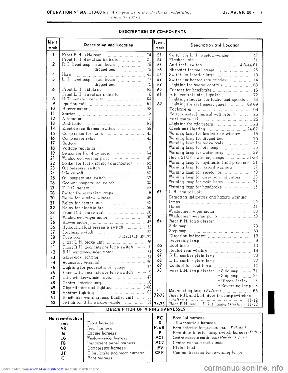
Downloaded from www.Manualslib.com manuals search engine DESCRIPTION OF COMPONENTS
dent.
Ident.
Description ond Location
n ark Description and Location
mark
1
Front R.H sidelamp
74 53
Switch for L.H. window-winder .,, 47
Front R H direction indicator
21 54 Flasher unit
.... 21
2 R.H. headlamp
main beam
78 55 Anti-theft switch
4-a-44-61
dipped beam
76 56 Rheostat for fuel gauqe
,.. 25
4 Horn
41 57
. Switch for interior lamp .,. 10
5 L.H headlamp main beam
.., .., ,.. 77 58
Switch for heated rear window
14
dipped beam”: 75 59 Lighting for heater controls _.. 68
6 Front L H sidelamp
.,. 69 60
Contact for handbrake .._....
16
Front L.H. direction indicator ,.... ._. _._.. 16 61
8 R.H control unit (lighting )
72
H T
sensor connector ,. 64
Lighting rheostat for tacho and speed0
28
9
Ignition coil ,.,
61 62 Lighting for instrument panel 68-69
10
Blower motor 58
Tachometer
.,.
64 11
Starter 3 Battery meter ( thermal voltmeter ) 26 12 Alternator ..I
5
Fuel gauqe unit 25 13
Distributor
61 14 Lighting for odometers _. 28 Electric fan thermal switch 59
Clock and lighting .._.. .,. 24-67
15
Compressor for horns 43 Warning lamp for heated rear window
15 16 Compressor relay 42 Warning lamp for dipped beam
_.. 75 17
Battery 1 Warninq lamp for brake pads 27 18 Voltage regulator . . . . . . . . . . 6 Warning lamp for oil temp. ,,_.. 35
19
Sensor for No 4 cylinder
64 Warning lamp for water temp. ..._.,,, ,,,,. 29 21
Windscreen washer pump ... .. ......
40 Red (( STOP )) warning lamps
31-33 22
Socket for fault-finding (diagnostic) .‘.‘.... 65 Warninq lamp for hydraulic fluid pressure
31 23
Oil pressure switch 34 Warning lamp for hazard warning
17 24 Idle cut-off .._........ 60
Warning lamp for sidelamps
70 25
Oil temperature switch 35 Warning lamp for direction indicators 23 26
Coolant temperature switch 30 Warninq lamp for main beam .‘..... 77 27 ‘I’D f-, SenSOr 63
Warning lamp for handbrake ... .‘........-.. 16 28
Switch for reversinq lamps ... ... ....... 8 63 L H control unit 30
Relay for window -winder ... ... .‘........ 49 Direction indicators and hazard warning 31
Relay for heater unit 45 lamps .,. .,...._ .,. .._ 19
.,. .._.......... 32
Relay for electric fan 58 Horns 41 33
Front R H. brake unit
.._.. 28 Windscreen wiper motor
..,.... 38 34
Windscreen wiper motor
_.............. 38 Windscreen washer pump
.._...... 40 35
Blower motor, ,._..._._....._._..._........ 45 64 Rear R.H. lamp cluster 36
Hydraulic fluid pressure switch _..._......... 32 Sidelamp .._...... 73
37
Stoplamp switch 53 S toplamp
_. _. _. _. _. _. _. 53
.._..............
38
Fuse box 8-44-45-49-69-72 Direction indicator
19
_.. _._.. 39
Front L.H. brake unit
. .._.._............... 26 Reversing lamp 9 41
Front R.H. door interior lamp switch 10
6665 Boot lamp .._. ._. 13
42
R.H. window-winder motor ..- 51 Heated rear window
14 43
Glove&or lightinq .._............ 51 67 R.H. number plate lamp 70
44
Accessory terminal 50 68 _..,......... L.H. number plate lamp
72 45
Lighting for pneumatic oil qauge 33 h9 Contact for boot lamp .._.. .._. .._........ 12 46
Front L.H. door interior lamp switch 9 70 Rear L.H. lamp cluster
- Sidelamp
71 47
L.H. window-winder motor ..: 47 - Stoplamp .._._... 52
48
Central interior lamp
10 - Direct. indic. 18 49
Cigar-lighter and lighting 9-66 - Reversing lamp 8
.._....
50 Ashtray lighting 67 71 Map-reading lamp f Pnl/ns ) .._..._....._.
66
_._......._...................... 51
Handbrake warning lamp flasher unit .._._.._ 15 72-73 Rear R.H. and L.H. door int. lamp switches 52
Switch for R.H. window-winder _..._.. 51 (P(/llgs ) 1 l-12 74-75 Rear R.H. and L.H. int. lamps ( f’nlins ) 1 l-12 DESCRIPTION OF WIRING HARNESSES
No identification PC
Boot lid harness mark
Front harness D <( Diagnostic )) harness AR
Rear harness P.AR Rear interior lamps.harness f I’n//nc )
M Engine harness F
Rear door interior lamp switch harness (Pflj/~.s LG
Window-winder harness MC1 Centre console earth lead( Pall~.~,’ S~/jczr ) TB
Instrument panel harness MC2 Centre console earth lead
co Compressor harness Flying lead UF
Front brake pad wear harness C: Contact harness for reversing lamps
C Boot harness
Page 324 of 394
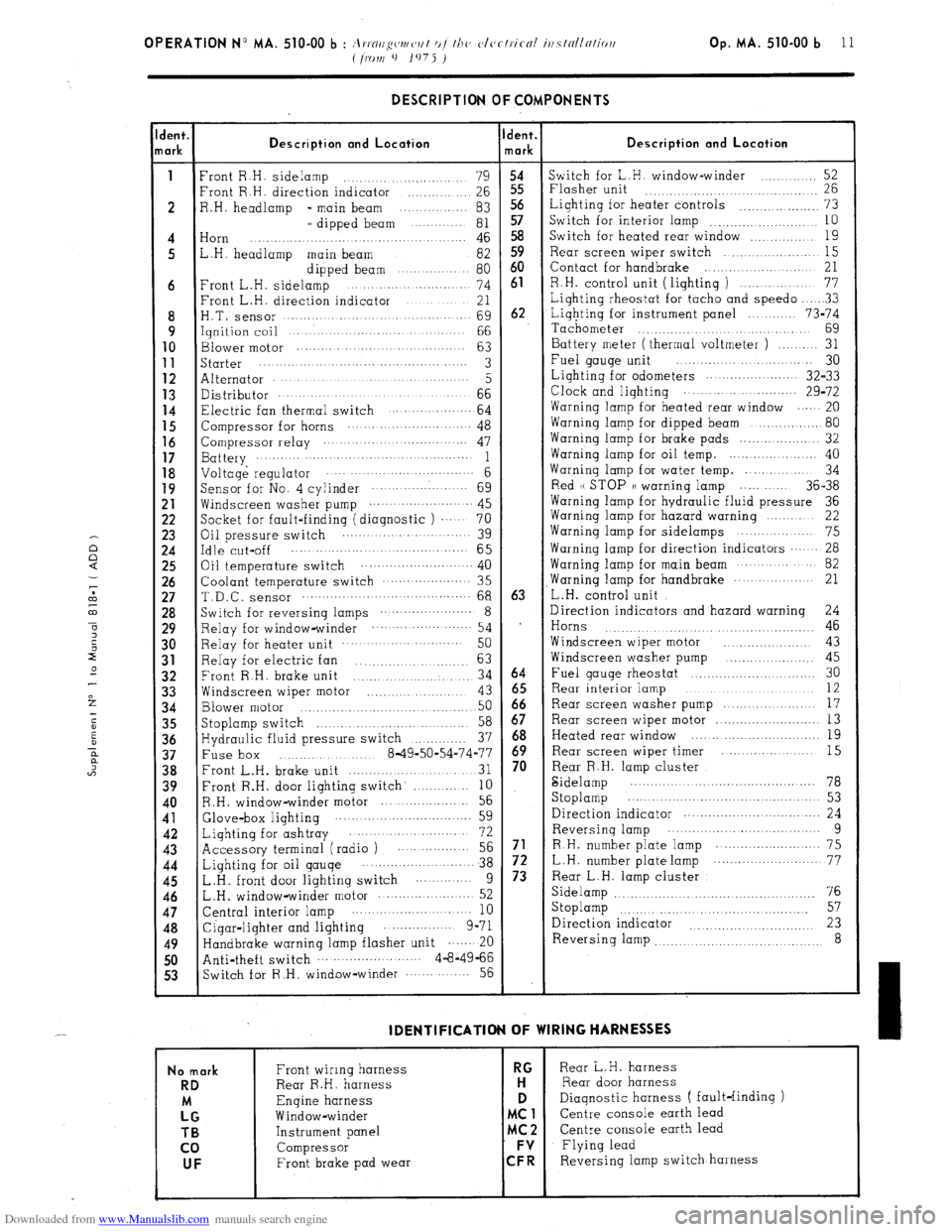
Downloaded from www.Manualslib.com manuals search engine Op. MA. 510-00 b 11 DESCRIPTION OF COMPONENTS
lent.
lark Description and Location Ident.
mark Description and Location
1
Front R.H. sidelamp
........................ 79
54 Switch for L.H. window-winder
..... ....... 52
Front R.H. direction indicator
.............. 26 55 Flasher unit
26 ....................................
2 R.H. headlamp - main beam ............... 83 Lighting for heater controls
................... 73
L dipped beam
........... 81 “5;
Switch for interior lamp
10 ..........................
4 Horn
.... 46 58 Switch for heated rear window
................ 19 ..................................
5 L.H. headlamp main beam
82 59 Rear screen wiper switch
.................... 15
Front L.H. sideli?pped..beam ... 80 60 Contact for handbrake
..................... 21
6 ............... ..
74 61 R.H. control unit ( lighting )
............... 77
Front L.H. direction indicator
............ 21 Lighting rheostat for tacho and speed0
.... ..3 3
8 H.T. Sensor .................................
69 62 Lighting for instrument panel
........ 73-74
9 Ignition coil
........................... 66
Tachometer .............................
69 10
Blower motor ...............
.................
63 Battery meter (thermal voltmeter )
........ 31 11 starter
...............................................
3 Fuel gauge unit ................ ..... ...... 30
12 Alternator ............................................
5 Lighting for odometers
...................... 32-33 13 Distributor
.... ......... .......... ..........................................
66 Clock and lighting
29-72 14
Electric fan thermal switch 64 Warning lamp for heated rear window ......
................. 20
15
Compressor for horns ........................... 48 Warning lamp for dipped beam
................. 80 16
Compressor relay .............................. 47 Warning lamp for brake pads
................... 32 1’;
Battery ...........................................
1 Warning lamp for oil temp. ...................... 40
Voltage regulator .............................. 6 Warning lamp for water temp. ............. 34
19
Sensor for No. 4 cylinder ....................
69 Red (( STOP )) warning lamp ..... ..... 36-38
:: Windscreen washer pump ....... ................. 45
Warning lamp for hydraulic fluid pressure 36
Socket for fault-finding (diagnostic )
.... 70 Warning lamp for hazard warning
....... 22 23
Oil pressure switch ..........................
39 Warning lamp for sidelamps .......
.......... 75 :“5
Idle cut-off ....................................... 65 Warning lamp for direction indicators ...... 28
Oil temperature switch ..................... ... .. 40 Warning lamp for main beam
........... 82
:; Coolant temperature switch
.....................
35 ,Warning lamp for handbrake
............... 21
T.D.C. sensor .......................................... 68 63
L.H. control unit
28 Switch for reversing lamps ....................... 8
Direction indicators and hazard warning
24
29 Relay for window-winder ........................
54 1
Horns 46 .............. ............... ..........
30 Relay for heater unit
........................
50 Windscreen wiper motor
.. .............. 43
31
Relay for electric fan ................
63 Windscreen washer pump .................... 45
32
Front R.H. brake unit
.................... 34 64 Fuel gauge rheostat ..............................
30
33 Windscreen wiper motor ........................... 12
................ 43 65 Rear interior iamp
34 Blower motor 50 66
Rear screen washer pump ...................
17
................... ................. 35
Stoplamp switch
58 67 Rear screen wiper motor
.......................... 13
..........................
36 Hydraulic fluid pressure switch
37 68 Heated rear window ...............................
19
..............
;‘8 Fuse box 8-49-50-54-74-77 ;; Rear screen wiper timer ....................
15
............. .........
Front L.H. brake unit
............................... 31 Rear R.H. lamp cluster
39 Front R.H. door lighting switch’
............ 10 Sidelamp
.......................................... 78
10 R.H. window-winder motor
................... 56 Stoplamp ..............................................
53 11
Glove-box lighting 59 Direction indicator ..................................
24 ...... ...........................
42
Lighting for ashtray 72 Reversing lamp ... ........... ............ .......
9 .....................
43 Accessory terminal (radio ) .................. 56 71
R.H. number plate lamp .......................... 75
44
Lighting for oil gauge ........................ 38 72 L.H. number plate lamp ............... ... ....... 77
45
L.H. front door lighting switch
...........
9 73 Rear L.H. lamp cluster
46 L.H. window-winder motor
76 ..................... 52 Sidelamp
.............................................
47 Central interior lamp 57
..........................
10 Stoplamp
..........................................
48
Cigar-lighter and lighting ...............
9-71 Direction indicator 23 .........................
49 Handbrake warning lamp flasher unit ....... 20 Reversing lamp
8 ................................
50 Anti-theft switch
.......................... 4-8-4966
53 Switch for R.H, window-winder
............ 56 IDENTlFlCATlON OF WIRING HARNESSES
No mark
RD
LMG TB
co UF
Front wiring harness RG Rear L.H. harness
Rear R.H. harness H Rear door harness
Engine harness D
Diagnostic harness ( fault-finding )
Window-winder MC1
Centre console earth lead
Instrument panel MC2 Centre console earth lead
Compressor FV
Flying lead
Front brake pad wear CFR Reversing iamp switch harness
Page 338 of 394
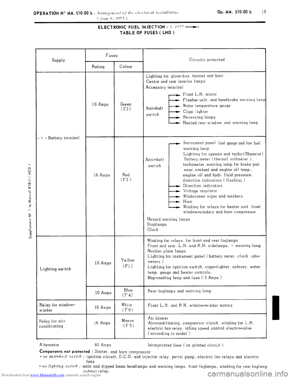
Downloaded from www.Manualslib.com manuals search engine Op. MA. 510-00 b 19 ELECTRONIC FUEL INJECTION ( i/ 1077 -)
TABLE OF FUSES ( LHD )
SUPPlY Fuses
Circuits protected
Ratinq Colour
Lightinq for qlove-box, bonnet and boot
Centre and rear interior lamps
Accessory terminal
Front L.H. mirror
16 Amps Green (F-2)
Flasher unit. and handbrake warninq lam1
Anti-theft
E Water temperature gauge
switch Cigar lighter
Reversinq lamps
Heated rear window, and warning lamp
+ )) Battery terminal
Instrument panel fuel gauge and low fuel
warninq lamp
Anti-theft
switch Liqhtinq for speed0 and tacho ( Rheostat )
16 Amps
(RFe3d)
_ Battery meter (thermal voltmeter ).
tachometer, warning lamp for brake pad
wear, coolant and engine oil temp. 1
enqine oil and hydr. fluid pressure.
direction indicators ( flashing )
Direction indicators
Voltage requlator
Windscreen wiper and washers
Horn
Windinq for relays for heater unit front
window-winders and horn compressor
Hazard warning lamps
Stoplamps
Clock
Winding for r-elays, for front and rear foglamps
Front and rear, L.H. and R.H. sidelamps, + warninq lamp
Number plate lamps
Lighting switch 10 Amps Yellow Liqhtinq for instrument panel (battery meter. clock. odo-
meters )
(Fl) Lighting for iqnition switch, cigar-lighter, ashtray, water
temp. gauge and heater controls.
Map-reading lamp and fuse ( 5 Amps )
10 A.mps Blue
(F4) Rear foglamps and warninq lamp
Relay for window-
winder 16 Amps White
Front L.H. and R.H. window-winder motors (FE)
Relay for air-
conditioning 16 Amps Mauve
(F5) Air blower
Air-conditioning, compressor clutch, windinq for L.H.
electric fan relay, idlinq speed control electro-valve
( according to model )
Alternator 81) Amps
Incorporated fuse ( on printed circuit ) Components not protected
: Starter, and horn compressor
- OII anti-theit .switrh : ignition circuit, E.C.U. and injector relay, petrol pump, electric fan relays and electric
fans
- cm lighting switch : main and dipped beam headlamps and warning lamps, front foglamps, winding for rear foglamp
cut-out relay.
Page 340 of 394
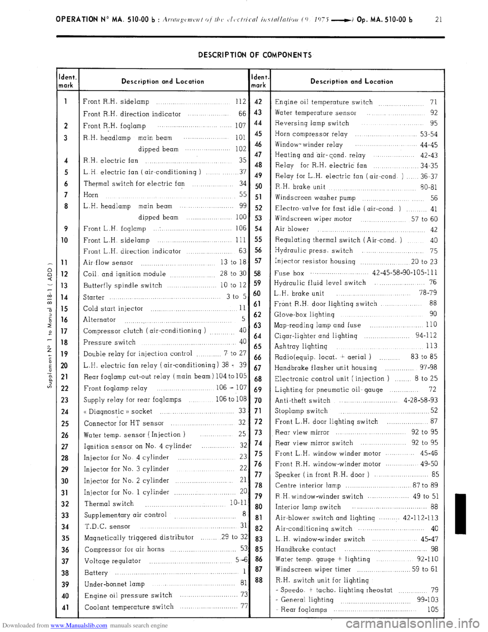
Downloaded from www.Manualslib.com manuals search engine OPERATION No MA. 510-00 b : A,.,.N//~w~/w/ of I/J<, c~l~~clriccrl iti7tollnliou (0 1075 -i Op. MA. 510-00 b 21 DESCRIPTION OF COMPONENTS
dent.
lark Description and Location Ident.
mark Description and Location
1
Front R.H. sidelamp ............................ 112 42
Engine oil temperature switch 71 ...............
Front R.H. direction indicator .... ... .........
66 43 Water temperature sensor .... .............. 92
2 Front R.H. foglamp 107 44 Reversing lamp switch ................... 95
..................... ....... ....
3 R.H. headlamp main beam
;:: :: Horn compressor relay ..................... 53-54
............... ....
dipped beam Window- winder relay .................. 44-45
......................
47
Heating and air-cond. relay ...............
4 R.H. electric fan ............................... 35 42-43
48
.............. 34-35
5 LH electric fan ( air--conditioning ) Relay for R.H. electric fan
........ 37 49
Relay for L.H. electric fan (air-cond. ) ..... 36-37
6 Thermal switch for electric fan .............. 34 50
R.H. brake unit
........... 80-81
......... ............
7 Horn
....................................
.......... ..... 55 51
Widscreen washer pump .............. .... 56
8 L.H. headlamp main beam ........... ..........
gg 52 Electra-valve for fast idle (air-cond. ) ......... 41
dipped beam ......................
100 53
Windscreen wiper motor ............. 57 to 60
9 Front L.H. foglamp ... . ...............................
106 54
Air blower ..............
........... ..... ........... 42 10
Front L.H. sidelamp ......................... ... ... .. 111 55 Regulating thermal switch (Air-cond. ) .... 40
Front L.H. direction indicator
63 56 ................... Hydraulic press. switch .......................
75 11
Air-flow sensor 13 to 18 57
........................... ... Injector resistor housing .................... .20 to 23 12
Coil. and ignition module
28 to 30 58 Fuse box ............................ 42-45-58-90-105-l 11
................. 13
Butterfly spindle switch 10 to 12 S9 Hydraulic fluid level switch ...................... 76
.................... 14
Starter 3 t0 5 6o L.H. brake unit ........................ 78-79
..........................................
88 15
Cold start injector 11 61 Front R.H. door lighting switch ....... ....
.................................. 16
Alternator 5 62 Glove-box lighting ................................ 90
...........
....... ..................... ....... 17
Compressor clutch ( air-conditioning ) 40 63 Map-reading lamp and fuse ............... ..... ... 110
.........
64 18
Pressure switch 40 Cigar-lighter and lighting ...................... 94-l 12
........................................
65 Ashtray lighting 113 ..................................... 19
Double relay for injection control 7 to 27 ............ 66
Radio(equip. locat. t aerial ) .......... 83 to 85
20 L.H. electric fan relay (air-conditioning) 38 = 39 67
Handbrake flasher unit housing .............. 97-98 21
Rear foglamp cut-out relay (main beam) 104 to 105 68
Electronic control unit (injection ) ....... 8 to 25
22 Front foglamp relay ....................... .. 106 - 107 69
Lighting for pneumatic oil- gauge .............. 72
23
Supply relay for rear foglamps ............ 106 to 108 70
Anti-theft switch ............................ 4-28-58-93 24
u Diagnostic )) socket 52 ......... ....... ... ..... ........ 33 71 Stoplamp switch ...................................... 25
Connector for HT sensor 72 ................... 87
....................... 32 Front L.H. door lighting switch 26
Water temp. sensor ( Injection ) Rear view mirror ............................ 92 to 95
... 25 73
27
Ignition sensor on No. 4 cylinder 32 74 Rear view mirror switch ................... 92 to 95
............. 28
Injector for No. 4 cylinder ...................... 23 75 Front L.H. window winder motor .......... 45-46 29
Injector for No. 3 cylinder 22 76 Front R.H. window-winder motor .............. 49-50
...........................
......................... 85 30
Injector for No. 2 cylinder 21 77 Speaker ( in front R.H. door )
......................... 78 Centre interior lamp ............................... 87 to 89 31 Injector for No. 1 cylinder 20 ............................. 79 R H. window-winder switch .................... 49 to 51 32 Thermal switch
........... .......................... 10-11 8 o
Interior lamp switch .................... ................ 88
33 Supplementary air control ............................
8 81
Air-blower switch and lighting .......... 42-112-113 34 T.&c.
SenSOr ........................................... 31 82 Air-conditioning switch ............... ............ 40
35
Magnetically triggered distributor ........ 29 to 32 83
L.H. window-winder switch .....................
45-47 36
Compressor for air horns ............. ..... ......... 53 85 Handbrake contact ......................................... 98 37
Voltage regulator 5-6 86 Water temp. gauge + lighting ..................
92-110
....................................... 38
Battery 1 87 Windscreen wiper timer
.......................... 59 to 61
....................................................... 39
40
41
Under-bonnet lamp ........................................ 81 88 R.H. switch unit for lighting
Engine oil pressure switch 73 - Speedo. t tacho. lighting rheostat ............ 79
............................
99-103
Coolant temperature switch 77
- General lighting ................................
....... ....................
- Rear foglamps ..................................... 105
Page 355 of 394
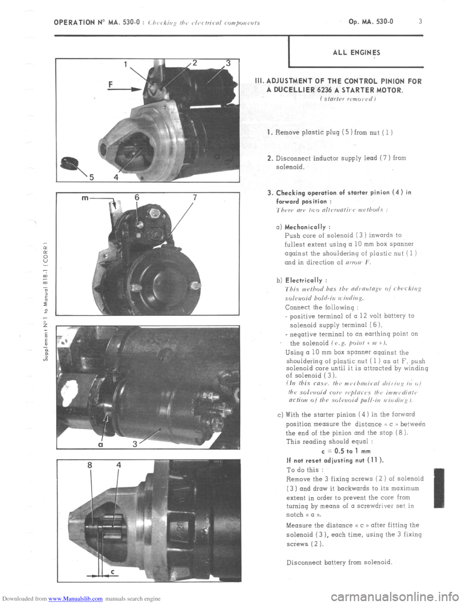
Downloaded from www.Manualslib.com manuals search engine m- 6 7 3. Checking operation of starter pinion (4) in
/ forward position :
7hcrc “lP ,,c,, nllrn,nli,~r~ rn<~~h”LS : OPERATION No MA. 530-O : (./ 1< ‘ ,,,g II,‘, vl<~rtricnl rompo,,w,ls , -k’ Op. MA. 530-O 3
ALL ENGINES
III. ADJUSTMENT OF THE CONTROL PINION FOR
A DUCELLIER 6236 A STARTER MOTOR.
f Sl”l’,Pl xmor~rdI
1.
Remove plastic plug (5) from nut ( 1 )
2. Disconnect inductor supply lead (7 ) from
solenoid. a) Mechanically :
Push core of solenoid (3 ) inwards to
fullest extent using a 10 mm box spanner
against the shouldering of plastic nut (1 )
and in direction of nrmw r.
b) Electrically :
'rbis ,w!hod has fh~ ndr'ontopr~ of rfwrking
solomid holrl.irz rrirdivg.
Connect the Iollowing :
positive terminal of (I 12 volt battery to
solenoid supply termina1 (6 ),
_ negative terminal to an earthing point on
the solenoid f V.R. poisl GC VI )) %
Using a 10 mm box spanner oqainst the
shouldering of plastic nut (1 ) as at F, push
solenoid core until it is attracted by winding
of solenoid ( 3 ).
fIrI this msr. fbc nr~~rhn~~irnl hi, irip ri 0,
!hc solwoid COY<, r<~plor<~s I/?<, i,,?“,<~diOl<~
or/ion 0i the solwoid pull-i,, vi,,di~~ 1.
c) With the starter pinion (4 ) in the forward
position measure the distance /, c )r betwe&
the end of the pinion and the stop (8 ).
This reading should equal : c = 0.5 to 1 mm
If not reset adjusting nut (11 ).
To do this :
Remove the 3 fixing saews (2 ) of solenoid
(3 ) and draw it backwards to its maximum
extent in order to prevent the core from
turning by means of a screwdriver set in
notch N a u.
Measure the distance I< c 1) after fitting the
solenoid (3 ). each time, using the 3 fixing
screws ( 2 ‘J.
Disconnect battery
from solenoid.
Page 357 of 394
Downloaded from www.Manualslib.com manuals search engine OPERATION No MA. 530.0 : Chcrking the vlr,rtricol components Op. MA. 530.0 5
I ALL ENGINES
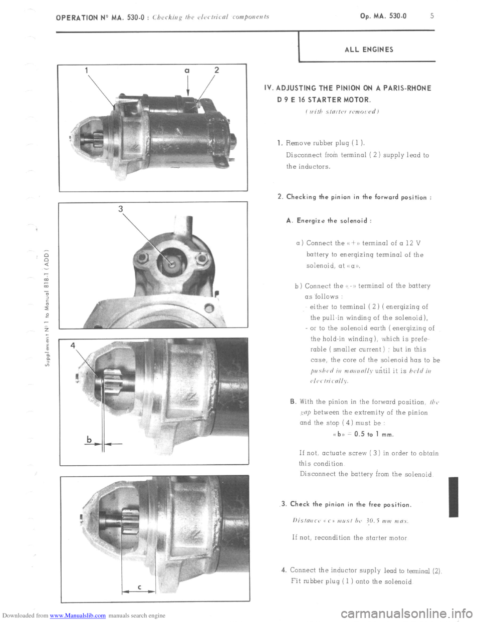
IV. ADJUSTING THE PINION ON A PARIS-RHONE
D 9 E 16 STARTER MOTOR.
i wirh s,orfw lcmo~ <‘d)
1.
Remove rubber pluq (1 1.
Disconnect from terminal ( 2 ) supply lead to
the inductors. 2. Checking the pinion in the forward position :
A. Energize the solenoid :
a ) Connect the u + >a terminal of a 12 V
battery to energizing terminal of the
solenoid, at NCIU.
b) Connect the GS -B) terminal of the battery
as ‘follows :
either to terminal (2) ( enerqizinq of
the pull-in winding of the solenoid),
OI to the solenoid earth ( enerqizing of
the hold-in winding ), which is prefe-
rable (smaller current) : but in this
case, the core of the solenoid has to be
pr~41crl iu mmanll~ uritil it is held iu
P/C< hi< nllv.
6. With the pinion in the forward position, I/Z<,
cop between the extremity of the pinion
and the stop ( 4) must be : s< bn 0.5 to 1 mm.
If not, actuate screw ( 3 1 in order to obtain
this condition
Disconnect the battery kxn the solenoid.
4. Connect the inductor supply lead to terminal (2)
Fit rubber plug ( 1 j onto the solenoid
Page 378 of 394
Downloaded from www.Manualslib.com manuals search engine OPERATION No MA. 642-W : ~Thnracteristics o/ thy, e I:Ko/I) - -70 3 hc,nriug s, stew Op. MA. 642-00 3
When starting : capsule is subjected to vacuum
Vacuum capsule
Westaflex tube
c J
J
COLD AIR
Closing plate for
SUPPLY SHUT OFF warm air supply
,
Flap B
I
to air filter
DIAGRAM.No. 1
‘acuum capsule not under vacuum
Flap
DIAGRAM No. 2
to air filter
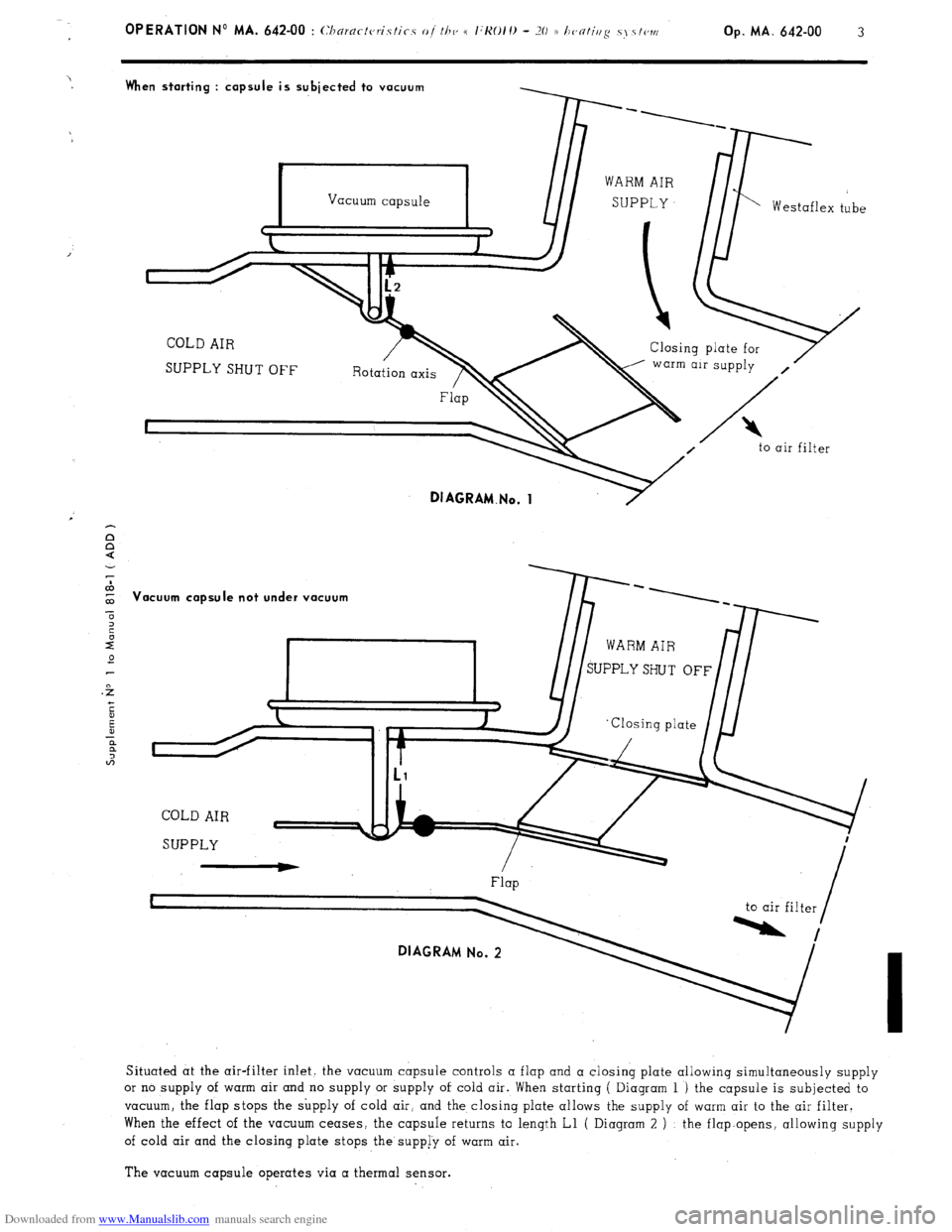
Situated at the air-filter inlet. the vacuum capsule controls a flap and a closing plate allowing simultaneously supply
or no supply of warm air and no supply or supply of cold air. When starting ( Diagram 1 ) the capsule is subjected to
vacuum, the flap stops the supply of cold air, and the closing plate allows the supply of warm air to the air filter.
When the effect of the vacuum ceases, the capsule returns to length Ll ( Diagram 2 ) : the flap.opens, allowing supply
of cold air and the closing plate stops the supp[y of warm air.
The vacuum capsule operates via a thermal sensor.