check engine Citroen CX 1981 1.G Workshop Manual
[x] Cancel search | Manufacturer: CITROEN, Model Year: 1981, Model line: CX, Model: Citroen CX 1981 1.GPages: 394
Page 2 of 394
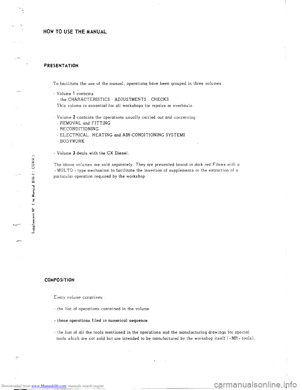
Downloaded from www.Manualslib.com manuals search engine HOW TO USE THE MANUAL
PRESENTATION
To facilitate the use of the manual. operations have been qrouped in three volumes
- Volume 1 contains
- the CHARACTERISTICS ADJUSTMENTS CHECKS
This volume is essential for all workshops for repairs or overhauls
Volume 2 contains the operations usually carried out and concerning
- REMOVAL and FITTlNG
- RECONDITIONING
- ELECTRICAL. HEATING and AIR-CONDITIONING SYSTEMS
BODYWORK
- Volume 3 deals with the CX Diesel.
cd
E The above volumes are sold separately. They are presented bound in dark red Fibrex with,a
1~ MULTO 1) type mechanism to facilitate the insertion of supplements or the extraction of a
-
cl3 particular operation required by the workshop
L
a COMPOSITION
Every volume comprises
- the list of operations contained in the volume
- these operations filed in numerical sequence
- the list of all the tools mentioned in the operations and the manufacturing drawings for special
tools which are not sold but are intended to be manufactured by the workshop itself (‘(MR)) tools).
Page 3 of 394
Downloaded from www.Manualslib.com manuals search engine OPERATIONS
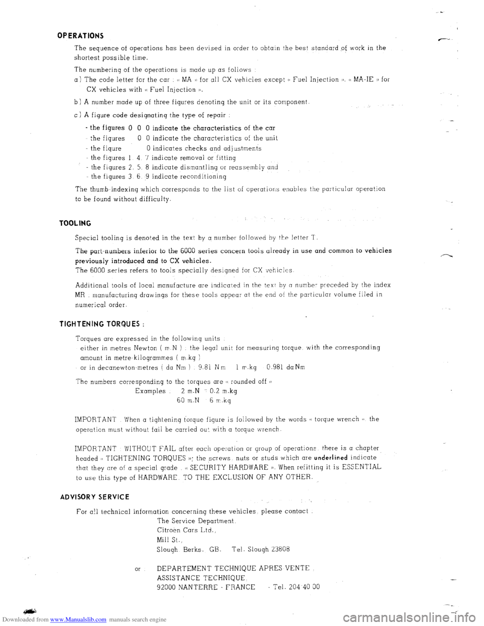
The sequence of operations has been devised in order to obtain the best standard of work in the
shortest possible time.
The numbering of the operations is made up as follows
a) The code letter for the car (/ MA 3) for all CX vehicles except
b ) A number made up of three figures denoting the unit or its component.
c ) A figure code designating the type of repair
- the figures 0 0 0 indicate the characteristics of the car
the figures 0 0 indicate the characteristics of the unit
- the figure 0 indicates checks and adjustments
the figures 1 4. 7 indicate removal or fitting
- the figures 2. 5. 8 indicate dismantling or reassembly and
the figures 3 6 9 indicate reconditioning
The thumb-indexing which corresponds to the list of operations enables the particular operation
to be found without difficulty. TOOLING
Special tooling is denoted in the text by a number followed by the letter ‘I
The part-numbers inferior to the 6000 series concern tools aiready in use and common to vehicles
previously introduced and to CX vehicles.
The 6000 series refers to tools specially designed for CX vehicles
Additional tools of local manufacture are indicated in the text by a number preceded by the index
MR manufacturing drawings for these tools appear at the end of the particular volume filed in
numerical order. TIGHTENING TORQUES :
Torques are expressed in the following units
either in metres Newton ( m.N ) the legal unit for measuring torque. with the corresponding
amount in metre-kilogrammes ( m.kg )
or in decanewtonmetres ( da Nm ) 9.8i Nm 1 m.kg ci.981 daNm
The numbers corresponding to the torques are (t rounded off 1)
Examples 2 m.N 0.2
m..kg 60 m.N 6
m.kg
IMPORTANT When a tightening torque figure is followed by the words 11 torque wrench 11 the
operution must without fail be carried out with a torque wrench.
IMPORTANT WlTHOUT FAIL after each operation or group of operations there is a chapter
headed (, TIGHTENING TORQUES ,,; the screws nuts or studs which are underlined
indicate
that they are of a special grade ,c SECURITY HARDWARE 1). When refitting it is ESSENTIAL
to use this type of HARDWARE TO THE EXCLUSION OF ANY OTHER. ADVISORY SERVICE
For a!1 technical information concerning these vehicles please contact
The Service Department,
Citroen Cars Ltd..,
Mill St.,
Slough Berks. GE. Tel. Slough 23808
or DEPARTEMENT TECHNIQUE APRES-VENTE
ASSISTANCE TECHNIQUE -
92000 NANTERRE - FRANCE - Tel. 204 40 00 :
.- ---
Page 4 of 394
Downloaded from www.Manualslib.com manuals search engine Operation
number
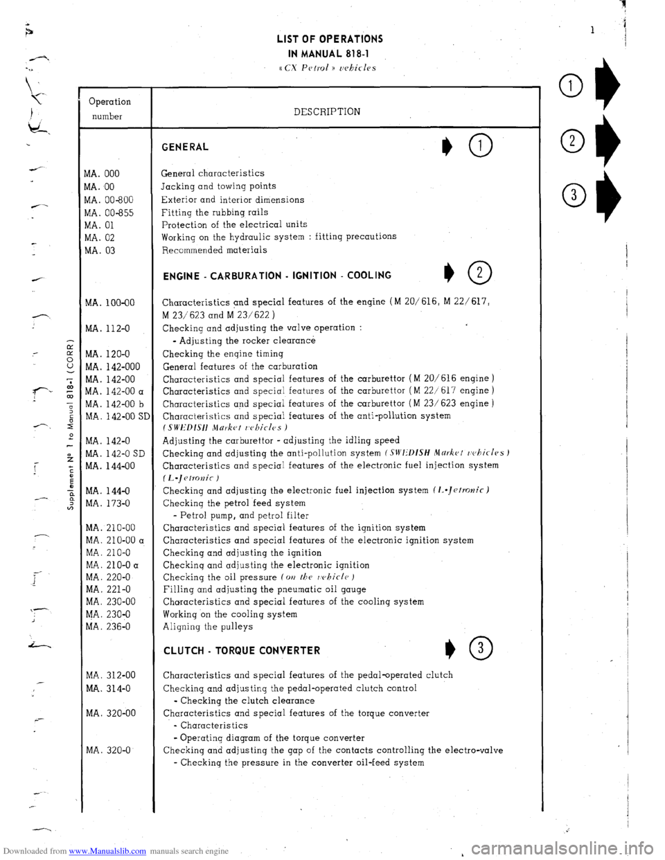
VIA. 000
VIA. 00
VIA. 00-600
vlA. 00-655
VIA. 01
WA. 02
MA. 03
MA. 100-00
MA. 112-O
MA. 120-O
MA. 142-000
MA. 142-00
MA. 142-00 a
MA. 142-00 b
MA. 142-00 SI
MA. 142-O
MA. 142-O SD
MA. 144-00
MA. 144-O
MA. 173-O
MA. 210-00
MA. 210-00 a
MA. 210-O
MA. 210-O a
MA. 220-O
MA. 221-O
MA. 230-00
MA. 230-O
MA. 236-O
MA. 312-00
MA. 314-O
MA. 320-00
MA. 320-O LIST OF OPERATIONS
IN MANUAL 818-l
cc CX Petrol )) uehicles
DESCRIPTION GENERAL
General characteristics
Jacking and towing points
Exterior and interior dimensions
Fitting the rubbing rails
Protection of the electrical units
Working on the hydraulic system : fitting precautions
Recommended materials ENGINE - CA,RBURATlON - IGNITION - COOLING
+O 2
Characteristics and special features of the engine (M 20/616, M 22/ 617,
M 23/623 and M 23/622 )
Checking and adjusting the valve operation :
- Adjusting the rocker clearance
Checking the engine timing
General features of the carburation
Characteristics and special features of the carburettor (M 20/616 engine )
Characteristics and special features of the carburettor ( M 22/617 engine )
Characteristics and special features of the carburettor ( M 23/ 623 engine )
Characteristics and special features of the anti-pollution system
I SWEDISH Jlurket r,c~kicles )
Adjusting the carburettor - adjusting the idling speed
Checking and adjusting the anti-pollution system
(SIVI:‘DfSH Mdrkct rvhicles J
Characteristics and special features of the electronic fuel injection system
(L.~etKJnic )
Checking and adjusting the electronic fuel injection system (1..Jetrolzic)
Checking the petrol feed system
- Petrol pump, and petrol filter
Characteristics and special features of the ignition system
Characteristics and special features of the electronic ignition system
Checking and adjusting the ignition
Checkinq and adjusting the electronic ignition
Checking the oil pressure (on
the rvhicle )
Filling and adjusting the pneumatic oil gauge
Characteristics and special features of the cooling system
Working on the cooling system
Aligning the pulleys CLUTCH - TORQUE CONVERTER
*O 3
Characteristics and special features of the pedal-operated clutch
Checking and adjusting the pedal-operated clutch control
- Checking the clutch clearance
Characteristics and special features of the torque converter
- Characteristics
- Operating diagram of the torque converter
Checking and adjusting the gap of the contacts controlling the electro-valve
- Checking the pressure in the converter oil-feed system
Page 5 of 394
Downloaded from www.Manualslib.com manuals search engine .r.
-/1
LIST OF OPERATIONS
IN MANUAL 818-1
a CX Petrol )) 7,rhifles
--
-
f-7
i---- _--
-
Operation
number
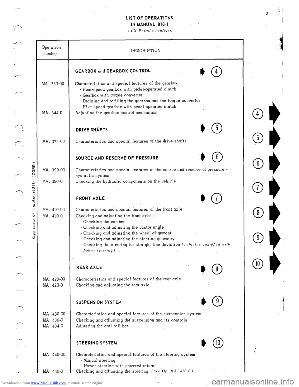
MA. 330-00
MA . . 344-O
MA. 372-00
MA. 390-00
MA. 390-O
MA. 410-00
MA. 410-O
MA. 420-00
MA. 420-O
MA. 430-00
MA. 430-O
MA. 434-O
MA. ,440-00
MA. 440-O DESCRIPTION GEARBOX and GEARBOX CQNTROL
*O 4
Characteristics and special features of the gearbox
- Four-speed gearbox with pedal-operated clutch
- Gearbox.with torque converter
- Draining and refilling the gearbox and the torque converter
- Five-speed gearbox with pedal-operated clutch
Adjusting the gearbox control mechanism DRIVE SttiFTS
Characteristics and special features of the drive-shafts SOURCE AND RESERVE OF PRESSURE
Characteristics and special features of the source and reserve of pressure -
hydraulic system
Checking the hydraulic components on the vehicle FRONT AXLE
+O 7
Characteristics and special features of the front axle
Checking and adjusting the front axle :
- Checking the camber
- Checking and adjusting the castor angle
- Checking and adjusting the wheel alignment
- Checking and adjusting the steering geometry
- Checking the steering for straight line deviation (
whirfes cjq77ippcJrl with REAR AXLE
*O 8
Characteristics and special features of the rear axle
Checking and adjusting the rear axle SUSPENSION SYSTEM
I,0 9
Characteristics and special features of the suspension system
Checking and adjusting the suspension and its controls
Adjusting the anti-roll bar STEERING SYSTEM
*@
Characteristics and special features of the steering system
- Manual steering
- Power steering with powered return
Checking and adjusting the steering (see Op. MA. 410-O )
Ob
4
Ob 5
Ok 6
Ok 7
O+ 8
O1) 9
Page 6 of 394
Downloaded from www.Manualslib.com manuals search engine LIST OF OPERATIONS
IN MANUAL 818-l
Operation
number
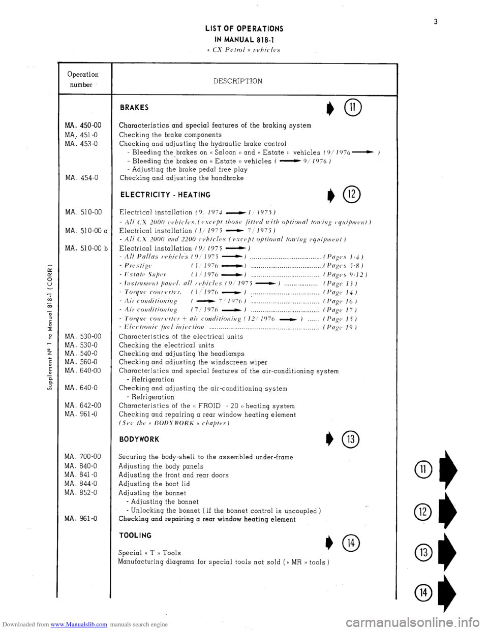
MA. 450-00
MA,. 451-O
MA. 453-O
MA. 454-O
MA. 510-00
MA. 51 O-00 a
MA. 510-00 b
MA. 530-00
MA. 530-O
MA. 540-O
MA. 560-O
MA. 640-00
MA. 640-O
MA. 642-00
MA. 961-O
MA. 700-00
MA. 840-O
MA. 841-O
MA. 844-O
MA. 852-O
MA. 961-O DESCRIPTION BRAKES
Characteristics and special features of the braking system
Checking the brake components
Checking and adjusting the hydraulic brake control
- Bleeding the brakes on (( Saloon )) and (( Estate H vehicles (‘)/ lO76- )
- Bleeding the’brakes on (( Estate )) vehicles (
-911976)
- Adjusting the brake pedal free play
Checking and adjusting the handbrake ELECTRICITY - HEATING
I,0 12
Electrical installation ( 9, 1074 -1,1975)
- All C..X 2000 t’cJllicl0.Y. ( cJ.vc-u[)t those 1.ittcd with optimnl towitzg (,rjriiptueflt )
Electrical installation ( I/ 1975 - 711975)
- All <.X 2000 nrtcl 2200 I c>hiclcs (esrept optiwnl towing ccjrli/mv~~t )
Electrical installation ( c)/ 1 !J7 5 - J
- All Pnllas whirlck (Of 1975 :.I __._._.___............................ (Pfiges j-4)
- Prc,.s tige (I 1976 ----tJ . . . . . . . . . . . . . . . . .._.................. (Pngc~s 5-8)
- Estntc SIIpw IIf 1976 -1 . . . . . . . . . . . . . . . . . . . . . . . . . . . . . . . . . . . . (Pugc,s 9-12 )
- I~~strriv~cut pajf~,I. nil r~c~hicles (9!’ 1975 - ) . ( Page 13 )
- Tvrqrl~~ COIlI erter. (l/l976 - ) . . . . . . . . . . . . . . . . . . . . . . . . . . . . . . . . . . . . ( I’ogc, 14 )
- Air rotiditioffir~g ( - 7:
1076 ) : . . . (PcIgc- 16)
- Air covditiorli,lg (7! 1976 - J . . . .
- ‘l’orytrc~ coilr’f’rter + air contlitiotfirfg ( 12/ 1976 - )
- I?Iect~~r~ic j&l
if~iectiov . . . . . . . . . . . . . . . . . . . . . . . . . . . . . . . . . . . . . . . . . . . . . . . . . .
Characteristics of the electrical units
Checking the electrical units
Checking and adjusting the headlamps
Checking and adjusting the windscreen wiper
Pngc 17)
Pogc 15 )
Pup 19)
Characteristics and special features of the air-conditioning system
- Refrigeration
Checking and adjusting the air-conditioning system
- Refrigeration
Characteristics of the (( FROID - 20 )) heating system
Checking and repairing a rear window heating element
(Set, r/JP cc I~OI~~‘WOKK 1) rilnptc~rj
BODYWORK
*0 13
Securing the body-shell to the assembled under-frame
Adjusting the body panels
Adjusting the front and rear doors
Adjusting the boot lid
Adjusting the bonnet
- Adjusting the bonnet
- Unlocking the bonnet ( if the bonnet control is uncoupled )
Checking and repairing a rear window heating element TOOLING
Special (( T )) Tools *O 14
Manufacturing diagrams for special tools not sold (cc MR )) tools )
O1)
11
Ol) 12
Ok 13
O1) 14
Page 41 of 394
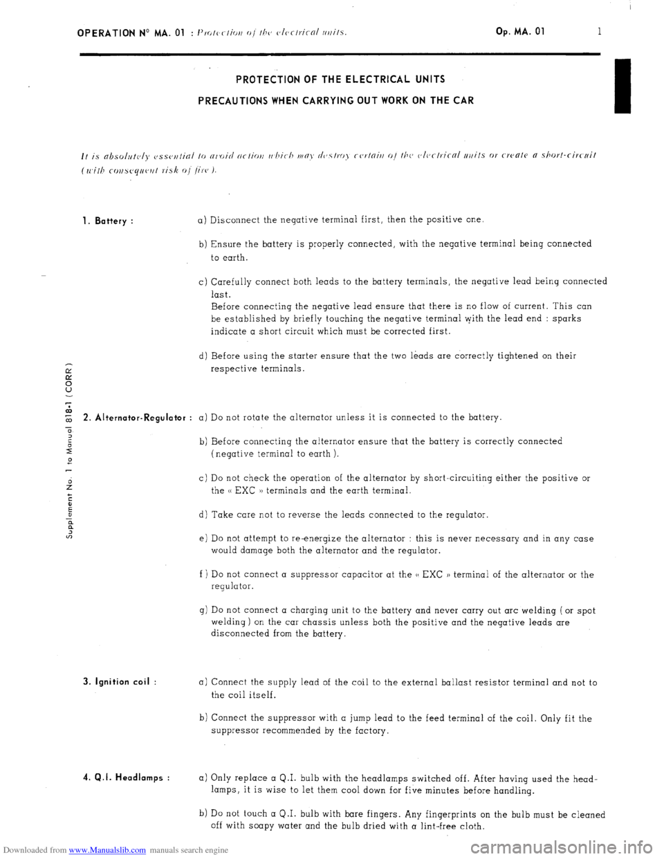
Downloaded from www.Manualslib.com manuals search engine OPERATION No MA. 01 : 1’. I, -1’ IO c ( lOi, o/ I/J<, c~lcrlricnl /l/lilS. Op. MA. 01 1 PROTECTION OF THE ELECTRICAL UNITS
PRECAUTIONS WHEN CARRYING OUT WORK ON THE CAR
1. Battery :
a) Disconnect the negative terminal first, then the positive one.
b) Ensure the battery is properly connected, with the negative terminal being connected
to earth.
c) Carefully connect both leads to the battery terminals, the negative lead being connected
last.
Before connecting the negative lead ensure that there is no flow of current. This can
be established by briefly touching the negative terminal pith the lead end : sparks
indicate a short circuit which must be corrected first.
d) Before using the starter ensure that the two leads are correctly tightened on their
respective terminals. $ 2. Alt ernator-Regulator :
a) Do not rotate the alternator unless it is connected to the battery.
0
2
2 b) Before connecting the alternator ensure that the battery is correctly connected
2 (negative terminal to earth ).
c) Do not check the operation of the alternator by short-circuiting either the positive or
the u EXC )) terminals and the earth terminal.
d) Take care not to reverse the leads connected to the regulator.
e) Do not attempt to re-energize the alternator : this is never necessary and in any case
would damage both the alternator and the regulator.
f ) Do not connect a suppressor capacitor at the u EXC )) terminal of the alternator or the
regulator.
g) Do not connect a charging unit to the battery and never carry out arc welding ( or spot
welding) on the car chassis unless both the positive and the negative leads are
disconnected from the battery. 3. Ignition coil :
4. Q.I. Headlamps :
a) Connect the supply lead of the coil to the external ballast resistor terminal and not to
the coil itself.
b) Connect the suppressor with a jump lead to the feed terminal of the coil. Only fit the
suppressor recommended by the factory.
a) Only replace a Q.I. bulb with the headlamps switched off. After having used the head-
lamps, it is wise to let them cool down for five minutes before handling.
b) Do not touch a Q.I. bulb with bare fingers. Any fingerprints on the bulb must be cleaned
off with soapy water and the bulb dried with a lint-free cloth.
Page 42 of 394
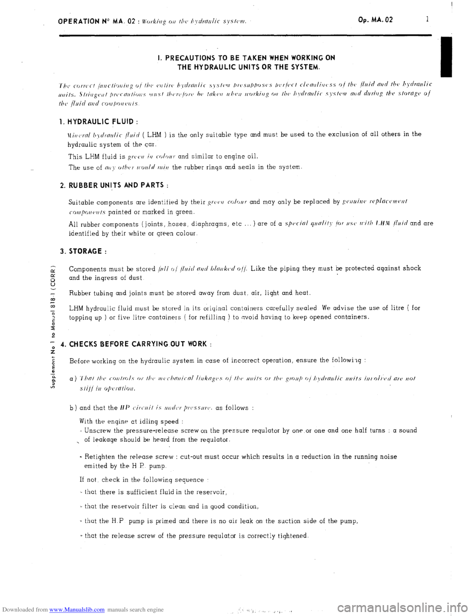
Downloaded from www.Manualslib.com manuals search engine 1. HYDRAULIC FLUID :
\~ir/~rol 6jr/rol,/ir j111icl ( LHM ) is the only suitable type and must be used to the exclusion of all others in the
hydraulic system of the car.
This LHM fluid is gt~‘~,l
iv c-o/or/~ and similar to engine oil.
The use of nr!~’ oih~~- rc,otll$
twirl the rubber rinqs and seals in the system 2. RUBBER UNITS AND PARTS :
Suitable components are identified by their grcc’r/ colo/~r and may only be replaced by gc~rttri~ro wplor-c~t~~c~nf
col,,pollc,l/fs painted or marked in green.
All rubber components (joints, hoses, diaphragms, etc . . . ) are of a
spvcirfl qtrnlif), ior ~/.SCJ wifh idlfM (Iuid and are
identified by their white or green colour, 3. STORAGE :
ix Components must be stosed /11i1 o/ /Irlirl nr~tl blor~k~rl o!j: Like the piping they must be protected against shock
E and the inqress of dust
7 Rubber tubing and joints must be stored away from dust. air, light and heat.
al
co
0 LHM hydraulic fluid must be stored in its original containers carefully sealed We advise the use of litre ( for
: toppinq up ) or five litre containers ( for refillinq ) to avoid havinq to keep opened containers.
2
2 T-, 4. CHECKS BEFORE CARRYING OUT WORK :
Z +
c
E Before working on the hydraulic system in case of incorrect operation, ensure the following :
a
a a) T/FOI the c-r>ufrol.y or f/l<, rnc~ch~uir~~l livkrrgc~s o/ //I(’ uuits or f/lo gmltp o/ h\~d~c~u/i~ ~~~~it.s in(nln>d are HO/
lt?
sfi]/ it) o/~c,rnfiou.
b) and that the 111’ c-ire-/ii/ is ////(/(jr /~I.(Jss/II.(J. as follows :
With the engine at idling speed :
- Unscrew the pressure-release screw on the pressure requlator by one or one and one half turns : a sound
, of leakage should be heard from the requlator.
= Retighten the release screw : cut-out must occur which results in a reduction in the running noise
emitted by the H P pump.
If not check in the following sequence
- that there is sufficient fluid in the reservoir,
- that the reservoir filter is clean and in good condition,
= that the H.P pump is primed and there is no air leak on the suction side of the pump,
- that the release screw of the pressure requlator is correctly tightened
Page 43 of 394
Downloaded from www.Manualslib.com manuals search engine 2
OPERATION No MA. 02 : I!‘orki//g OI/ hyc/rt/t/lic s\,s/vN/.
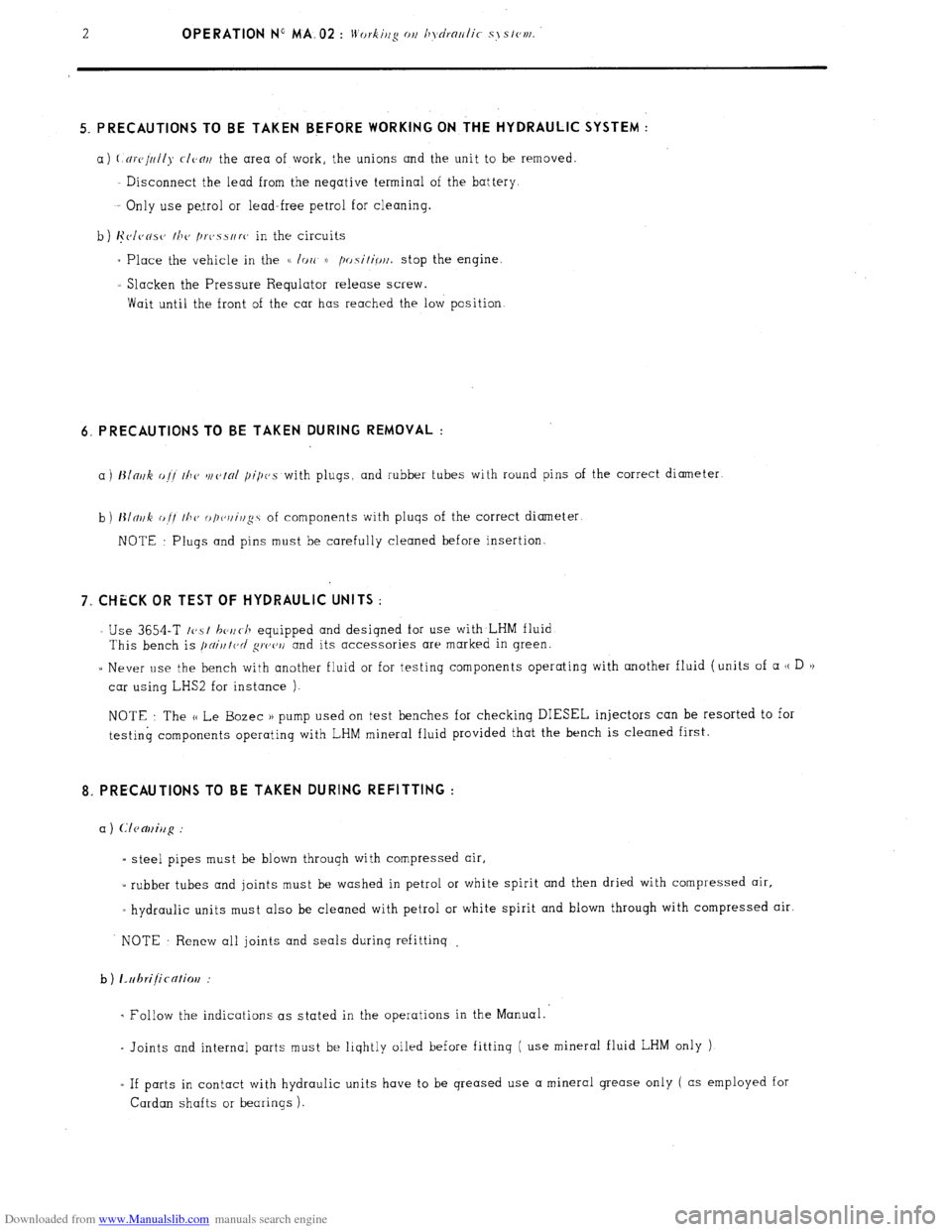
5. PRECAUTIONS TO BE TAKEN BEFORE WORKING ON THE HYDRAULIC SYSTEM :
a) (.~rvJuI/)~ CIVOII the area of work, the unions and the unit to be removed
Disconnect the lead from the negative terminal of the battery
Only use petrol or lead-free petrol for cleaning.
b ) I~~J/VNSO
the /)twsure in the circuits
- Place the vehicle in the G /arc B
position. stop the engine.
- Slacken the Pressure Requlator release screw.
Wait until the front of the car has reached the low position 6, PRECAUTIONS TO BE TAKEN DURING REMOVAL :
a) t3lnuk o!! the w~~tnl pi/~es with plugs, and rubber tubes with round pins of the correct diameter
b)
t3lmk of/ //IV op,c,/li,lg.s of components with pluqs of the correct diameter
NOTE : Plugs and pins must be carefully cleaned before insertion. 7.. CHECK OR TEST OF HYDRAULIC UNITS :
- Use 3654-T t~sf hc~~c-h equipped and designed for use with LHM fluid
This bench is /)ciitltc’d ~IY’~‘~/ and its accessories are marked in green.
- Never use the bench with another fluid or for testing components operating with another fluid (units of a (( D ))
car using LHS2 for instance ).
NOTE The (< Le Bozec )) pump used on test benches for checking DIESEL injectors can be resorted to for
testing components operating with LHM mineral fluid provided that the bench is cleaned first. 8. PRECAUTIONS TO BE TAKEN DURING REFITTING :
E steel pipes must be blown through with compressed air,
5 rubber tubes and joints must be washed in petrol or white spirit and then dried with compressed air,
= hydraulic units must also be cleaned with petrol or white spirit and blown through with compressed air.
NOTE Renew all joints and seals during refittinq .
b
) 12rlbrijicntim :
- Follow the indications as stated in the operations in the Manual..
- Joints and internal parts must be liqhtly oiled hefore fitting ( use mineral fluid LHM only )
L If parts in contact with hydraulic units have to be qreased use a mineral grease only ( as employed for
Cardan shafts or bearings ).
Page 44 of 394
Downloaded from www.Manualslib.com manuals search engine OPERATION No MA. 02 : I+ 4’ 0, “‘g 01, Ill<, l1\~c!).ollli(- s\‘sfell~. Op. MA. 02
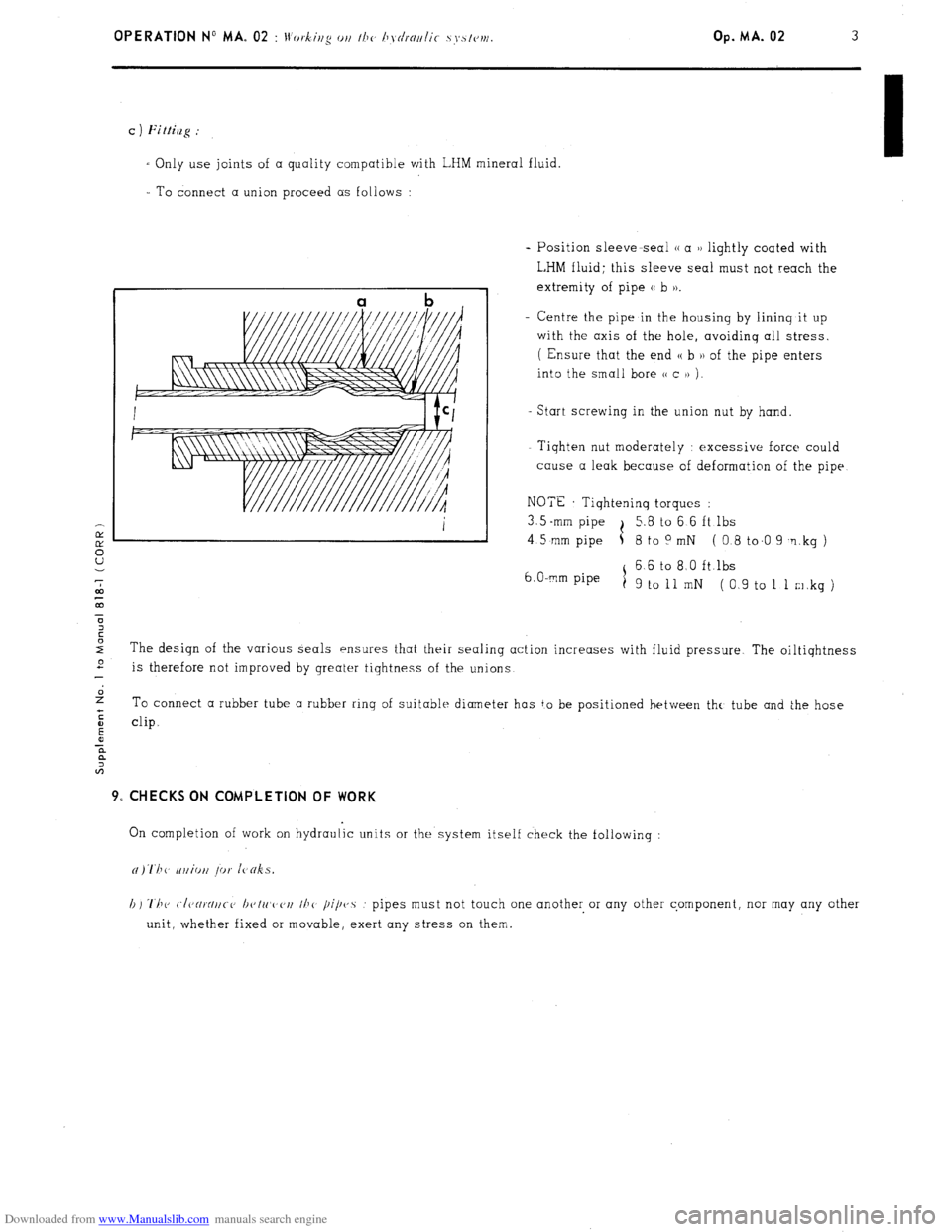
I To connect a union proceed as follows :
- Position sleeve-seal (( a u lightly coated with
L,HM fluid; this sleeve seal must not reach the
extremity of pipe (( b )).
- Centre the pipe in the housinq by lininq it up
with the axis of the hole, avoidinq all stress.
( Ensure that the end u b )I of the pipe enters
into the smali bore C< c )> j.
Start screwing in the union nut by hand.
- Tiqhten nut moderately : excessive force could
cause a leak because of deformation of the pipe
NOTE Tiqhteninq torques :
3.5 -mm pipe t 5.8 to 6 6 ft lbs
4 5 mm pipe 5 8 to 0 mN ( 0.8 to.0 9 ‘1 kg )
6 6 to 8 0 ft.lbs
6. O-mm pipe
1
9 to 11 mN (0 9 to 1 1 m.kg ) c ) Fittilzg :
I Only use joints of a quality compatible with LHM mineral fluid.
The design of the various seals ensures that their sealing action increases with fluid pressure The oiltiqhtness e
is therefore not improved by greater tiqhtness of the unions
2 To connect a rubber tube a rubber rinq of suitabie diameter has to be positioned between thr, tube and the hose
:
E clip.
0
x
a
A 9, CHECKS ON COMPLETION OF WORK
On completion of work on hydraulic units or the system itself check the followinq :
h) ‘1’11~ C./CJ~~~IIC-C, I~c,lrt,c,c,rt I/J<
pipvs : pipes must not touch one another or any other component, nor may any other
unit, whether fixed or movable, exert any stress on them.
Page 66 of 394
Downloaded from www.Manualslib.com manuals search engine OPERATION No MA. 100-00 : Characteristics and special features of the engine. Op. MA. 100.00 15
b) Timing chain :
- Clearance between the chain and the chain guide : . . . . . . . . . . . . . . . . . . . . . . . . . . 0.10 to 0.50 mm
c) Rockers :
- Length of push rods :
- Inlet : . . . . . . . . . . . . . . . . . . . . . . . . . . . . . . . . . . . . . . . . . . . . . . . . . . . . . . . . . . . . . . . . . . . . . . . . . . . . . . . . . . . . . . . . . . . . . . 189.10 ‘, Og’Q5 mm
- Exhaust : . . . . . . . . . . . . . . . . . . . . . . . . . . . . . . . . . . . . . . . . . . . . . . . . . . . . . . . . . . . . . . . . . . . . . . . . . . . . . . . . . . . . . . . 213.35 + 0.3
- 0.75 mm
- Maximum out of true of pushrods : . . . . . . . . . . . . . . . . . . . . . . . . . . . . . . . . . . . . . . . . . . . . . . . . . . . . . . . 1 mm
- Rocker clearance (engine cold) :
-Inlet : . . . . . . . . . . . . . . . . . . . . . . . . . . . . . . . . . . . . . . . . . . . . . . . . . . . . . . . . . . . . . . . . . . . . . . . . . . . . . . . . . . . . . . . . . . . . . . 0.15mm
- Exhaust : . . . . . . . . . . . . . . . . . . . . . . . . . . . . . . . . . . . . . . . . . . . . . . . . . . . . . . . . . . . . . . . . . . . . . . . . . . . . . . . . . . . . . . . . 0.20 mm
7. Flywheel :
2 - Distance between the clutch mechanism thrust face, and the 0 u clutch disc thrust face : . . . . . . . . . . . . . . . . . . . . . . . . . . . . . . . . . . . . . . . . . . . . . . . . . . . . . . . . . . . . . . . . . . . . . . . . . . . . 0.5 -is mm
7
co
G NOTE : It is essential to fit the diaphragm or flywheel mounting screws with LOCTITE FRENETANCH.
x
z - Correct fitting of starter ring : non machined face of the ring facing the flywheel shouldering.
s
2
E 8. Lubrication system :
5
z
6%
- Grade of oil . . . . . . . . . . . . . . . . . . . . . . . . . . . . . . . . . . . . . . . . . . . . . . . . . . . . . . . . . . . . . . . . . . . . . . . . . . . . . . . . . . . . . . . . . . . . . . . TOTAL ALTIGRADE GTS 20/W 50
2
- Capacity of sump :
- after dismantling : . . . . . . . .._................................................................. 5.800 litres ( IO.2 pts )
- after draining and changing the filter : : . . . . . . . . . . . . . . . l......................... 5.306 litres ( 9.3 pts )
- after draining : . . . . . . . . . . . . . . . . . . . . . . . . . . . . . . . . . . . . . . . . . . . . . . . . . . . . . . . . . . . . . . . . . . . . . . . . . . . . . . . . . . . 4.650 litres ( 8.2 pts )
- Oil pressure :
(At a temperature of 100 +‘S’ C)
- at 2000 rpm : . . . . . . . . . . . . . . . . . . . . . . . . . . . . . . . . . . . . . . . . . . . . . . . . . . . . . . . . . . . . . . . . . . . . . . . . . . . . . . . . . . . . . . . 3 .bar min. ( 43.5 psi )
- at 4000 rpm : . . . . . . . . . . . . . . . . . . . . . . . . . . . . . . . . . . . . . . . . . . . . . . . . . . . . . . . . . . . . . . . . . . . . . . . . . . . . . . . . . . . . . . 4 to 5 bar ( 58 to 72 l/2 psi )
- Calibration of pressure switch : . . . . . . . . . . . . . . . . . . . . . . . . . . . . . . . . . . . . . . . . . . . . . . . . . . . . . . . . . . . . . . . . 475 to 675 mbar ( 7 to 9.8 psi )
(warning lamp goes oat)
- Calibration of temperature switch (CX 2000 e Jan. 1975) : . . . . 1... 147’ to 150’ C
(warning lamp goes comes on)
(All CX vehicles Jan. 1975 -) : 135” to 138’ C
(warning lamp comes on )
- Calibration of relief valve spring :
- length of spring fully compressed : . . . . . . . . . . . . . . . . . . . . . . . . . . . . . . . . . . . . 31 mm
- length of spring under load of 10.9 kg : . . . . . . . . . . . . . . . . . . . . . . . . . . . . . . . . . . . . . . . . . . 42 mm
- Filter cartridge :
- calibration of (( by-pass )) valve : . . . . . . . . . . . . . . . . . . . . . . . . . . . . . . . . . . . . . . . . . . . . . . . . . . . . . . 550 mbar ( 8 psi )
NOTE : When changing the filter cartridge, check the cleanliness of the seal and’the contact area on the filter
housing.
- For removing and fitting the cartridge : . . . . . . . . . . . . . . . . . . . . . . . . . . . . . . . . . . . . . . . . . . . . . . . . . . . . Use Tool 6002-T