check engine Citroen CX 1981 1.G User Guide
[x] Cancel search | Manufacturer: CITROEN, Model Year: 1981, Model line: CX, Model: Citroen CX 1981 1.GPages: 394
Page 71 of 394
Downloaded from www.Manualslib.com manuals search engine OPERATION No MA. 120.0 : Chrrki,,~ the /iminp. Op. MA. 120-O 1
CHECKING THE TIMING.
lototing the crankshah :
) Vebirl~s /i/fed with a mantra~ gearbox :
Lift one of the front wheels of the vehicle, and
engage’ 4th or 5th gear so as to rotate the crank-
shaft,
by means of the raised wheel.
1) Vehicles /itted with n torqee ronrwrter :
Two methods are permissible to rotate the crank
shaft :
- feed the starter “iota from (I &volt battery,
or remove the protective plate under the
converter casing, and rotate the converter
using a screwdriver.
1. Remove :
spore wheel,
cylinder head (carburettor engine 1,
the injection manifold and the rocker cover
(fuel injection engine 1.
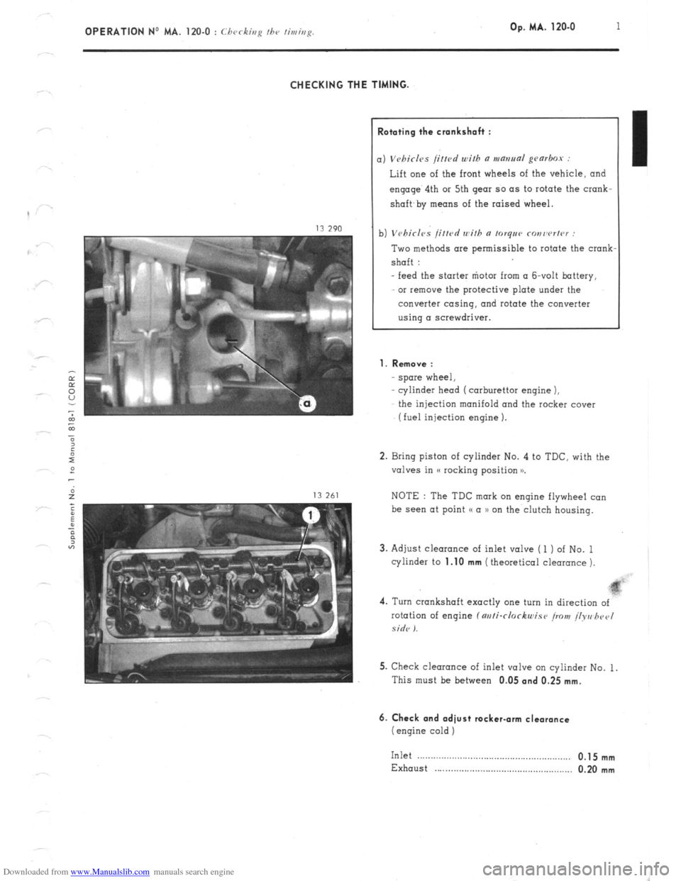
2. Bring piston of cylinder No. 4 to TDC. with the
valves in (( rocking position x
NOTE : The TDC mark on engine flywheel co”
be see” at point (( a )) on the clutch housing.
3. Adjust clearance of inlet valve ( 1 ) of No. 1
cylinder to
1.10 mm (theoretical clearance 1.
4. Turn crankshaft exactly one turn in direction of
rotation of engine f m/i-clockwise iro>t! /lyre hpel
side I.
5. Check clearance of inlet valve on cylinder No. 1.
This must be between 0.05
and 0.25 mm.
6. Check and adiust rocker-arm clearance
(engine cold )
Inlet .__....__.............................................,.,, 0.1 5 mm
Exhaust . . . . . . . . . . . . . . . . . . . . . . . . . . . . . . . . . . . . . . . . . . . . . . . . . . . . 0.20 mm
Page 77 of 394

Downloaded from www.Manualslib.com manuals search engine 6 OPERATION No MA. 142.000 : c ,Pi,r,rol ,cn,,,,cs 0, Ihc ~rwh,,m/ir,n.
III. REMOVING AND FITTING THE PROTECTIVE CAP FOR THE THROTTLE SPINDLE ON A SOLEX
CARBURETTOR (cap ( c ) ).
This operation is to be carried out only in the case of a check and odiustment on o carburettor test bench
(L’POLLU 2000 type ).
REMOVAL.
1, Remove cop ( c ) using flat-nose pliers.
2. Adjust the butterfly opening :
Adjust the butterfly opening using the test bench
according to the Norms laid down in the (< Etudes
Equipement 1) Nos : 14-1116 ter, and 14-l/16
quater, f SC,,, o>r rcc/ucs, ,o Ihr ,,scrs o, r-ml>,,-
~Cf,Ol /es, bcorhcs i.
FITTING.
3.
Fit cop ( c ) :
Load gun A.
- Screw tool H onto the gun.
Fit cop ( c ) onto the throttle spindle stop
screw.
Place the tool and gun assembly against the
cop ( C ) and actuate the gun.
Page 78 of 394
Downloaded from www.Manualslib.com manuals search engine OPERATION No MA. 142-000 : Gcnrrd 1.cnturcs 01. the cnrfxrr~tion. Op. MA. 142-000 7
In order to conform to current regulations, checking and adjustment the exhaust emission on u Petrol )) vehicles must
without fail be carried out after the following operations :
I. REPLACEMENT OF ENGINE.
II. REPLACEMENT OF CARBURETTOR.
Ill. WORKING ON THE CARBURATION
- Replacing the components of the carburettor
- Adjusting the carburettor
- Worki? - rri the carburettor controls
IV. WORKING ON THE INLET SYSTEM
Replacing or removing the following :
the inlet manifold,
- the air-filter,
- the crankcase gases recycling system.
V. WORKING ON THE ENGINE
Adjusting the rocker arms
Replacing or removing the following :
the cylinder head,
- the camshaft,
- the rockers,
- the valves,
_ the barrels and pistons.
VI. WORKING ON THE IGNITION
- Replacing or reconditioning the distributor ( partly or cpmpletely )
~ Adjusting or replacing the spark plugs
- Adjusting the ignition timing
VII. WORKING ON THE EXHAUST SYSTEM
Replacing or removing the following :
- the exhaust manifold,
- the exhaust pipe, or any other section of the exhaust system.
VIII. WORKING ON THE ANTI-POLLUTION SYSTEM
When the vehicle is fitted with special equipment C I c,hic-1~s /or SWIIllI:‘S. Al'S7'KAl.l~ll m;d JAI'A.\. /ot
Page 81 of 394
Downloaded from www.Manualslib.com manuals search engine OPERATION No MA. 142.00 : (.hornrt<,rislirs o,,d s,~“cinl ,<‘“,ur“s o! the Op. MA. 142.00 I(
rnrhrclfo,
CHECKING AND ADJUSTING OF THE FLOAT CHAMBER LEVEL
7 b
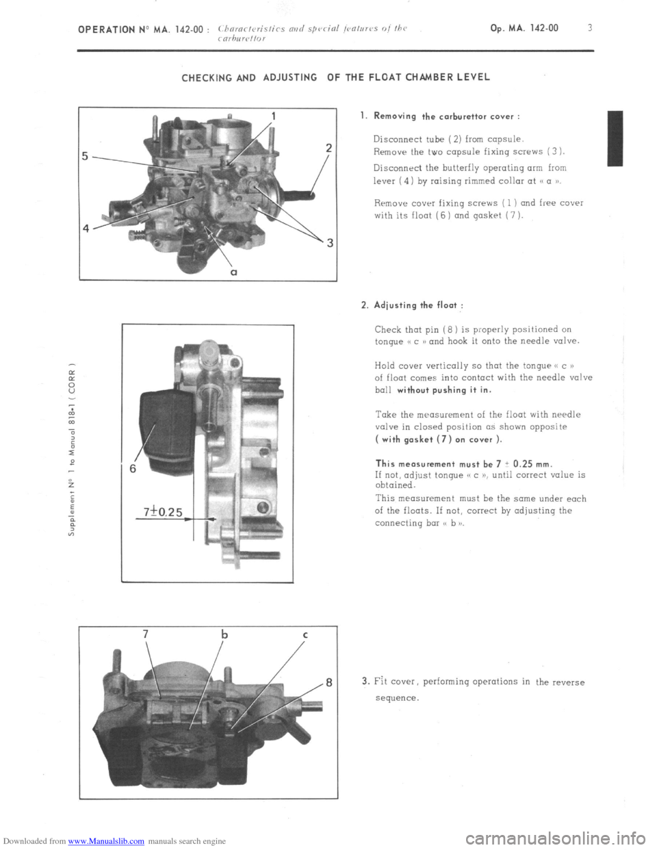
1. Removing the carburettor cover :
Disconnect tube (2) from capsule.
Remove the two capsule fixing screws (3
1.
Discollnrci the butterfly operating arm from I
lever (4) by raising rimmed collar at
Rrmove COWI fixing screws ( 1) and free cover
with its float (6 ) and gasket (7 ).
2. Adjusting the float :
Check that pin (8 ) is properly positioned on
tongue e c N and hook it onto the needle valve.
Hold ccwe~ vertically so thot the tongue e( c P)
of float comes into contact with the needle valve
ball
without pushing it in.
Take the measurement of the float with needle
valve in closed position as shown opposite
( with gasket (7) on cover ).
This measurement must be 7 i 0.25 mm.
If not, adjust tongue e c K until correct value is
obtained.
This measurement must he the same under each
of the floats. If not, correct by adjusting the
connecting bar ss b )I.
3. Fit cover, performing operations in the reverse
sequence.
Page 90 of 394
Downloaded from www.Manualslib.com manuals search engine OPERATION No MA. 142-O : Adj,,s/iaji f/a<, rarhnrt,//or Op. MA. 142.0
1
ADJUSTING THE IDLING SPEED
To carry out this adjustment, the following is needed
A tachometer
A device lor checkinq idling speed adjustments on the carburettor ( or on approved gas analyser )
- A CDA 23 checking oppmotus or a workshop test bench ( equipment mentioned in the Equipment and Repair
Materials list, or in the Tools and Equipment notes green notes )
NOTE : WEBER Carburettors ref. No W 54-50, 55-50, 69-50, 74-50 fitted on 1977 models onwards ore fitted with a
fool-proof plug ( white ) on the mixture screw. To adjust the exhaust emission, this plug has to be
removed, and
replaced, after adjustment, with a a Repair PI plug ( black ). See Op. MA, 142-000 for removing and fitting the plug,
and the necessary tools.
ADJUSTMENT CONDITIONS
1.
The idling speed adjus!ment must be carried out on an engine on which the rocker clearances and the ignition
are correctly set. with a clean air filter and
with the engine in good order.
2. Check that the butterflies return fully to their stops.
3. 30 not let pnythinq except the ignition and the engine cooling fan ( or ions ) impose any load on the alternator.
4. Run the engine to bring the
oil temperature up to 70 to 80’ C ( wait for the electric cooling fan ( or fans 1 to cut
in 1.
I. M 20/616, M 22/617, M 23/623 ENGINES I i< ?I< (5 wi/hr ,111 /or<,,,< co,1, <,r,cr or air ro,,di/io,ii?,g I ,I ‘-/
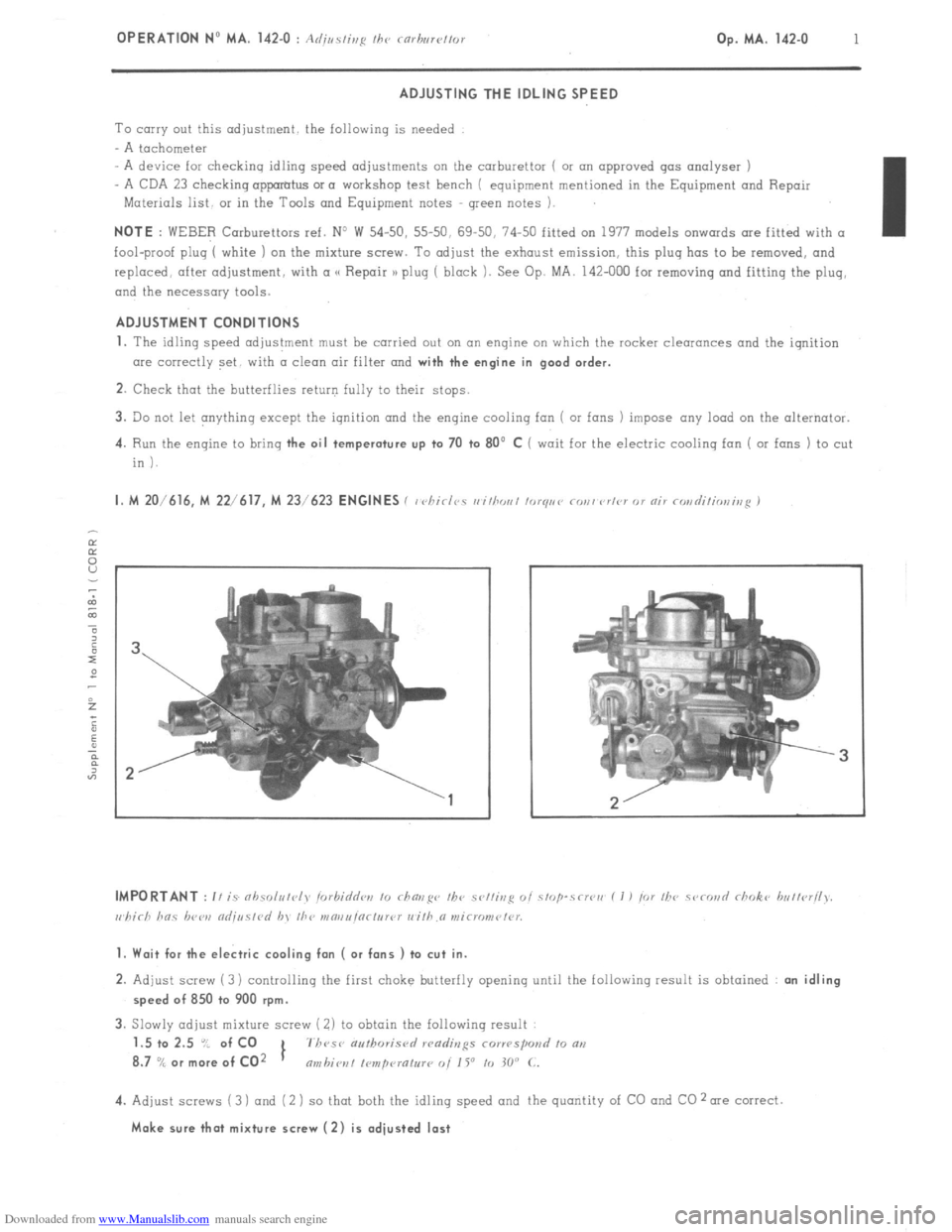
1. Wait for the electric cooling fan ( or fans ) to cut in.
2. Adjust screw (3) controlling the first choke butterfly opening until the following result is obtained : an idling
speed of 850 to 900 rpm.
3. Slowly adjust mixture screw ( 2) to obtain the following result
1.5 to 2.5 “/ of CO
1 7h~se authoris<,
8.7
% or more of CO2 nmbiot~l I~mpcuatur~ 0i 1 Y to 30” C.
4. Adjust screws (3 ) and (2 ) so that both the idling speed and the quantity of CO and CO 2 me correct.
Make sure that mixture screw (2) is adjusted last
Page 92 of 394
Downloaded from www.Manualslib.com manuals search engine OPERATION No MA. 142-O SD : (I k’ II c ,r,g m,d or/j,,r/ii,,~ /he m/i /dllllior, 5, Cl<‘,,i Op. MA. 142-O SD 1
f SIi’III)ISH \IAKKl:‘/ ,‘1,,,( 1.1’) ,
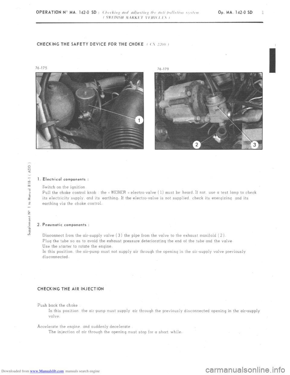
CHECKING THE SAFETY DEVICE FOR THE CHOKE i ( ?XO ,
2 1. Electrical components :
z
a Switch on the ignition
4 Pull the choke control knob the CC WEBER a) electto-valve ( 1) must be heard. If not use a test lamp to check
its electricity supply and its earthing. If the electro-valve is not supplied. check its energizinq and its
2
earthinq via the choke control.
5
;
E
; 2.P neurotic components :
?
“7
Disconnect from the air-supply valve ( 3 ) the pipe from the valve to the exhaust manifold ( 2 j
Plug the tube so as to avoid the exhaust pressure deteriorating the end of the tube and the valve
Use the starter to rotate the engine.
In this position the air-pump must not supply air through the opening in the air-supply valve previously
disconnecied.
CHECKING THE AIR INJECTION
Push bock the choke
In this position the air pump must supply air throuqh the previously disconnected opening in the air-supply
valve.
Accelerate the enqine. and suddenly decelerate
The injection of air through the openinq must stop for a short while.
Page 93 of 394
Downloaded from www.Manualslib.com manuals search engine 2
OPERATION No MA. 142.0 SD : (./ )I c ,,,s m,d nd;,,s/is~~ /A? Ni/li-/Joll,lli,,ill I \/i’V, b’
/ Sll l:l~/sl1 lI.\KKI:I v1:/1/c l.JT I,
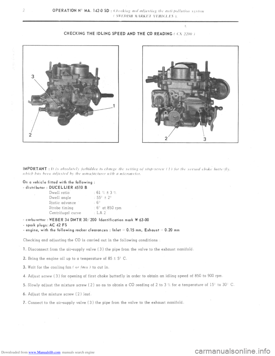
CHECKING THE IDLING SPEED AND THE CO READING I (.. JXO J
On cr vehicle fitted with the following :
-distributor : DUCELLIER 4510 B
Dwell ratio 61 7: + 3 ‘Y
Dwell angle 550 + 2”
Static advance 6”
Strobe timinq
6” at 850 rpm
Centrifuqal cuwe IA 2
- carburettor : WEBER 34 DMTR 30/200 Identification mark W 63-00
spark plugs: AC 42 FS
- engine, with the following rocker clearances : Inlet = 0.15 mm, Exhaust = 0.20 mm
Checking and adjusting the CO is carried out in the following conditions
1. Disconnect from the air-supply valve ( 3) the pipe from the valve to the exhaust manifold
2. Bring the engine oil up to a temperature of 85 ? 5’ C
3. Wait for the cooling ion ( 01
ims J to cut in.
4. Adjust screw ( 3) for opening of first choke butterfly in order to obtain on idling speed of 850 to 900 rpm
5. Slowly adjust the mixture screw (2) so (IS to obtain a CO reading of 2 to 3 “L for a temperature of 15” to 30 C
6. Adjust the mixture screw (2 ) lost
7. Connect to the air-supply valve (3 ) the pipe from the valve to the exhaust manifold.
Page 94 of 394
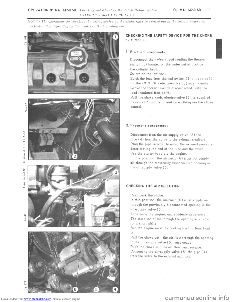
Downloaded from www.Manualslib.com manuals search engine CHECKING THE SAFETY DEVICE FOR THE CHOKE
f (.X 2000 j :
1. Electrical components :
Disconnect the u blur )) lead feeding the thermal
switch (1) located on the water outlet duct on
the cylinder head.
Switch on the ignition.
Earth the lead from thermal switch ( 1) the relay ( 2 )
for the << WEBER 1) electro-valve ( 3) must operate.
Leave the thermal switch disconnected with the
lead insulated from earth.
Pull the
choke knob. electro-valve (3) is supplied
by relay (2 ) and is closed by earthing via the choke
control.
2. Pneumatic components :
Disconnect from the air-supply valve ( 5) the
pipe (4) from the valve to the exhaust manifold.
Plug the pipe in order to avoid the exhaust pressure
deteriorating the end of the tube and the valve
Use the starter to rotate the engine.
In this position. the air pump (6 j must
not supply
air through the previously disconnected opening in
the air supply valve ( 5)
CHECKING THE AIR INJECTION
Push back the choke
In this position. the air-pump (6 ) must supply air
through the previously disconnected opening in the
air-supply valve ( 5 1.
Accelerate the engine, and suddenly decelerate
The injection of air throuqh the opening must stop
for a short while.
Run the engine until the cooling fan ( or fans ) cut
in.
Pull the choke out : the air flow through the opening
in the air supply valve ( 5) must cease.
Push the choke in : the air flow must resume.
Connect to the air-supply valve ( 5) the pipe ( 4 )
from the valve to the exhaust manifold.
Page 95 of 394
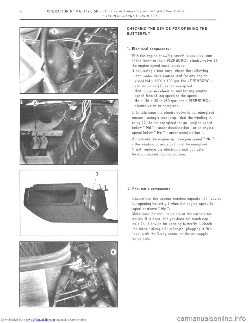
Downloaded from www.Manualslib.com manuals search engine CHECKING THE DEVICE FOR OPENING THE
BUTTERFLY
1. Electrical components :
With the engine at idling spu~d. disconnect one
of the leads to the C< PIERBURG ,) electro-valve (1).
the engine speed must increase.
If not. using a test lamp, check the following
that.
under deceleration and for any engine
speed
Nd > 1800 ? 100 rpm the /C PIERBURG >l
electro-valve (1 ) is not energized.
- that.
under acceleration and for any engine
speed from idling speed to the speed
Nc = Nd + 50 to 250 rpm. the C< PIERBURG ,,
electro-valve is energized.
If in this case the electro-valve is not energized.
ensure ( using a test lamp ) that the winding in
relay ( 2) is not enerqized for an engine speed
below ”
Nd ” ( under deceleration ) or an engine
speed below ”
NC ” ( under acceleration ).
Accelerate the engine up to engine speed ”
NC n :
- the winding in relay (2 ) must be enerqized.
If not. replace the electronic unit (3) after
having checked the connections.
2. Pneumatic components :
Ensure that the vacuum reaches capsule ( 4 1 ( device
for opening butterfly ) when the engine speed is
equal or above ”
NC “.
Make sure the vacuum exists at the carburettor
outlet. If it does. and yet does not reach cap-
sule (4) ( device for opening butterfly 1. check
the circuit along all its length. plugging it first
level with the 3-way union. on the air-supply
valve side.
Page 96 of 394
Downloaded from www.Manualslib.com manuals search engine OPERATION No MA. 142-O SD : (i ‘CC ,ii:: md nr/;,,sfinji //I<, “~,ti.pOlllLliol, .S,Sl~l,, k’
c s 11’1:/~12/1 ,\lAHKli’/ “,iH,(.,.li.S , Op. MA. 142-O SD 5
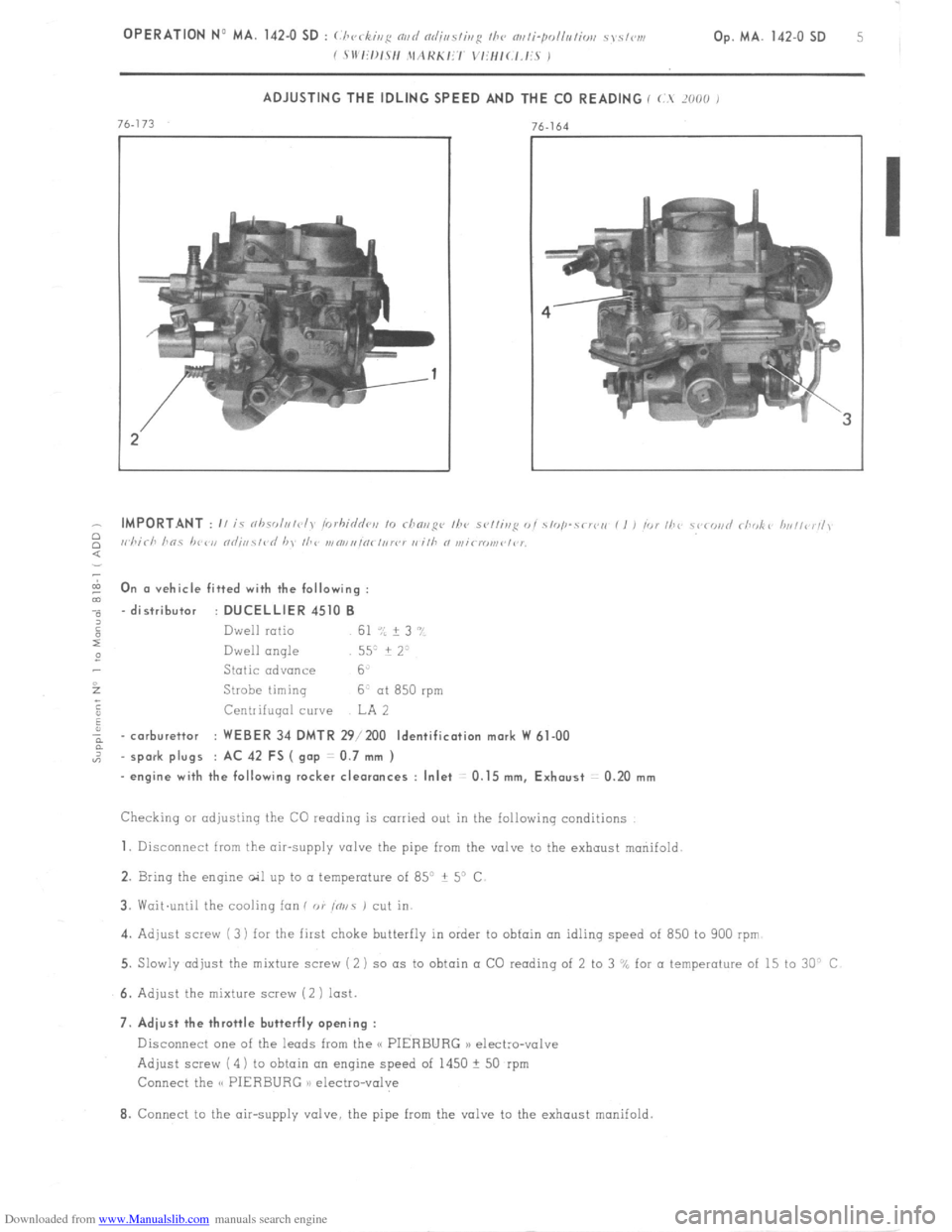
ADJUSTING THE IDLING SPEED AND THE CO READING ( (.. ‘01~0 I
- IMPORTANT : II i nhsr,l,,/<~l, irirhi<&,, ,o rhnri~q~, /he sv//ing o, .Y,<,,I-r< lo,, , I , ,o, //a~ ~i.
2 I, hirh hns /,<,,‘I, “
: 0
m n (I vehicle fitted with the following :
m
-.
“, - distributor : DUCELLIER 4510 B
6
Dwell ratio 61 ‘:: ? 3 ‘,
x
2 Dwell angle
557 i 2=
Static advance 6
i
Strobe liming 6. at 850 rpm
;
F Centrifugal curve LA 2
a
a - carburettor : WEBER 34 DMTR 29/200 Identification mark W 61-00
5
“2 - spark plugs : AC 42 FS ( g.ap : 0.7 mm )
- engine with the following rocker cleoronces : Inlet 0.15 mm, Exhaust : 0.20 mm
Checking or adjusting the CO reading is carried out in the following conditions
1. Disconnect from the air-supply valve the pipe from the valve to the exhaust mariifold.
2. Bring the engine ail up to a temperature of 85” ? 5” C.
3. Wait.until the cooling fan f or fnvs 1 cut in.
4. Adjust screw ( 3) for the first choke butterfly in order to obtain on idling speed of 850 to 900 rpm
5. Slowly adjust the mixture screw (2 ) so as to obtain a CO reading of 2 to 3 “A for a temperature of 15 to 30” C
6. Adjust the mixture screw (2 1 last.
7. Adiust the throttle butterfly opening :
Disconnect one of the leads from the S( PIERBURG n electro-valve
Adjust screw (4) to obtain on engine speed of 1450 + 50 rpm
Connect the S< PIERBURG n electro-valve
8. Connect to the air-supply valve, the pipe from the valve to the exhaust manifold.