check engine Citroen CX 1981 1.G Owner's Guide
[x] Cancel search | Manufacturer: CITROEN, Model Year: 1981, Model line: CX, Model: Citroen CX 1981 1.GPages: 394
Page 149 of 394
Downloaded from www.Manualslib.com manuals search engine 28 OPERATION N” MA.IE. 144-O : Ch <,c ,ng n,,d nlfjusfiup Ihe u I.-~<~tro,,ir i) <~lrr/mr,ir k’
/,,,.I i,,jrr/io,, S~S,W1, ANNEXE : D - ADJUSTING THE IDLING SPEED AND THE EXHAUST EMISSION
CHECKING CONDITIONS
1.
Checking the idling speed must be carried out
on a clean engine on which the ignition and the
valve clearances are properly adjusted and
fitted with a clean air-filter.
2. Check that the throttle butterfly returns correctly
to its stop.
3. Do not load the alternator by switching an any
of the electrical components, except the iqnition
and the electric cooling fan (s) 4.
Run the engine to bring the oil temperature up
to 70 +o 80’ C ( wait for the electric cooling
fan is) to cut in ). IMPORTANT : Use exclusively (I high tension
tachometer ( do not damage the H.T. lead of
the ignition wiring harness ).
ADJUSTMENT
1. Check that the butterfly is not jammed in position
when it is resting against its stop.
2. Wait for the electric cooling fan (s) to cut in.
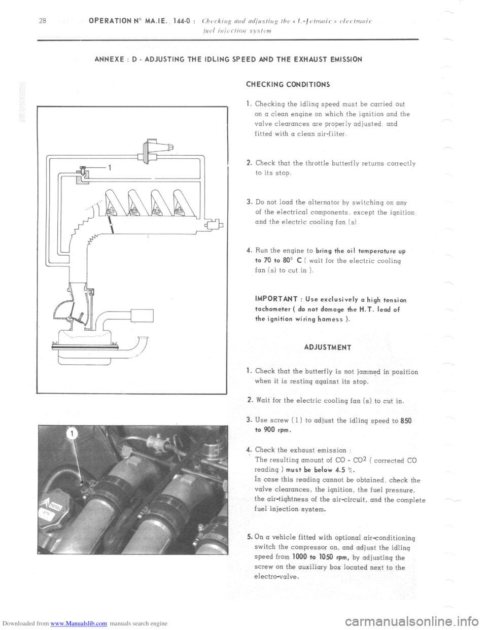
3. Use screw ( 1 ) to adjust the idling speed to 850
to 900 rpm.
4. Check the exhaust emission :
The resulting amount of CO - CO2 ( corrected CO
reading 1 must be beI& 4.5 %.
In case this reading cannot be obtained, check the
valve clearances, the ignition, the fuel pressure,
the air-tightness of the aircircuit, and the complete
fuel injection system.
5. On (I vehicle fitted with optional oirtonditioning
switch the compressor on, and adjust the idling
speed from 1000 to 1050
rpm, by adjusting the
screw on the auxiliary box located next to the
electro-vol”e.
Page 150 of 394
Downloaded from www.Manualslib.com manuals search engine OPERATION No MA. 173-O : Chrrkivp fhr prmd s,,pp/> Op. MA. 173.0 1
PETROL PUMP
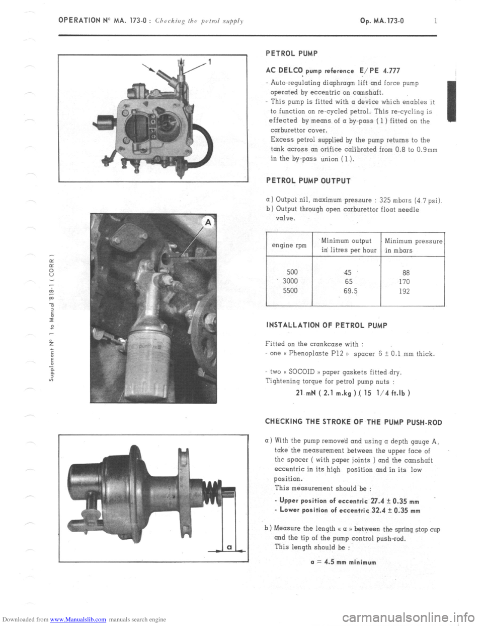
AC DELCO pump reference E/PE 4.777
Auto-regulating diaphragm lift and force pump
operated by eccentric on camshaft.
This pump is fitted with (I device which enables it
to function on re-cycled petrol. This re-cycling is
effected by means of a by-pass .( 1 ) fitted on the
carburettor cover.
Excess petrol supplied by the pump returns to the
tank across an orifice calibrated from 0.8 to 0.9mm
in the by-pass union (1).
PETROL PUMP OUTPUT
(I) Otitput nil, maximum pressure : 325 mbars (4 7 psi).
b) Output through open carburettor float needle
valve.
500 45 88
3000 65 170
5500 69.5 192
I I
Minimum pressure
in mbors
INSTALLATION OF PETROL PUMP
Fitted on the crankcase with :
one (( Phenoploste P12 )) spacer 5 + 0.1 mm thick.
two (< SOCOID a> paper gaskets fitted dry.
Tightening torque for petrol pump nuts :
21 mN ( 2.1 m.kg ).( 15 l/4 ft.lb )
CHECKING THE STROKE OF THE PUMP PUSH-ROD
a) With the pump removed and using (I depth gouge A,
take the measurement between the upper face of
the spacer ( with paper joints ) and the camshaft
eccentric in its high position and in its low
position.
This measurement should be :
- Upper position of eccentric 27.4 ? 0.35 mm
- Lower position of eccentric 32.4 rk 0.35 mm
b) Measure the length u a a) between the spring stop cup
and the tip of the pump control push-rod.
This length should be :
a = 4.5 mm minimum
Page 151 of 394
Downloaded from www.Manualslib.com manuals search engine 2 OPERATION No MA. 173.0 : C/ l<,C ,,,g //JP p/r”/ SuppI) k’
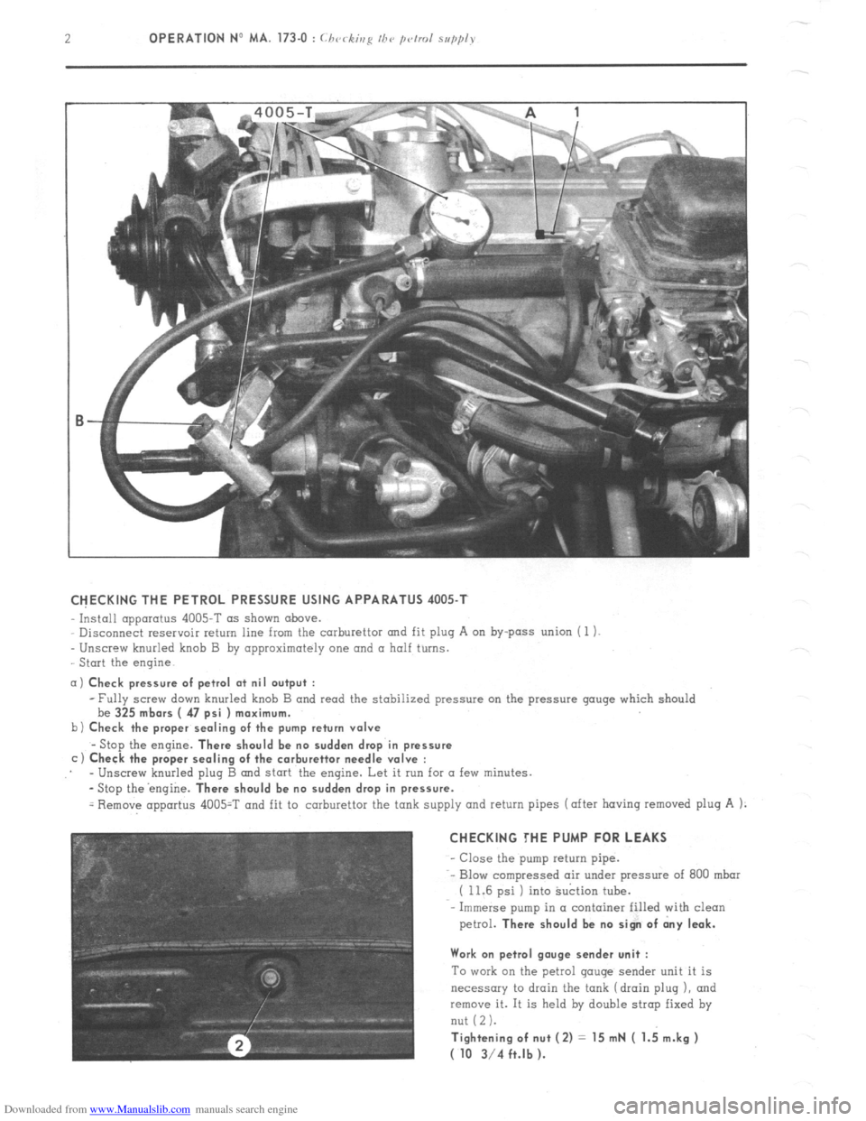
CHECKING THE PETROL PRESSURE USING APPARATUS 4005-T
Install apparatus 4005-T as shown above.
Disconnect reservoir return line from the carburettor and fit plug A on by-pass union ( 1 1.
Unscrew knurled knob B by approximately one and a half turns.
Start the engine
a) Check pressure of petrol at nil output :
b
c -Fully screw down knurled knob B and read the stabilized pressure on the pressure gouge which should
be 325
mbors ( 47 psi ) maximum.
Check the proper sealing of the pump return valve
-Stop the engine. There should be no sudden drop in pressure
Check the proper sealing of the carburettor needle valve :
- Unscrew knurled plug B and start the engine. Let it run for a few minutes.
-Stop theengine.
There should be no sudden drop in pressure.
= Remove apportus 4005=T and fit to carburettor the tank supply and return pipes (after having removed plug A 1:
CHECKING THE PUMP FOR LEAKS
- Close the pump return pipe.
-- Blow compressed air under pressure of 800 mbar
( 11.6 psi ) into Suction tube.
Immerse pump in a container filled with clean
petrol.
There should be no sign of dny leak.
Work on petrol gauge sender unit :
To work on the petrol gouge sender unit it is
necessary to drain the tank (drain plug 1, and
~emcwe it. It is held by double strap fixed by
nut (2 1.
Tightening of nut (2) = 15 mN ( 1.; m.kg )
( 10 3/4 ft.lb ).
Page 156 of 394
Downloaded from www.Manualslib.com manuals search engine OPERATION NO MA. 210-o : chcJckir,R fl,,d fld;linshp the, iRrlihil Op. MA. 210-O 1
M 20/616 M 22/617
M 23/623
ENGINES
1. Checking the dwell angle :
a) L’siep n SC,, 0, /C‘d‘,V gmg’s
Adjust the clearonce at the contact points to 0.40
mm I ‘Thic in,pwcic~~ wc,/hod iy PK,!
,I
ndr isvohle 1. ;i”
b) I’si,,fi a co,,, o,,~I<~ rh<,rkis~ drr’ir<, or RI,
,r 5.~~ :s
osri//risrop<~ :
The closing angle must be 55’ ? 2’30’
c) L’si,,g 0 d,,~r~ll,,,ct<~r :
The DWELL
ratio must be 61 i 3 .’ .‘.
.
2.
Checking the distributor timing :
i Disconnect the vacuum advance correction on 2350
cc engines M 23/623 )
a) hi,,c o \/robe lo,,,/~
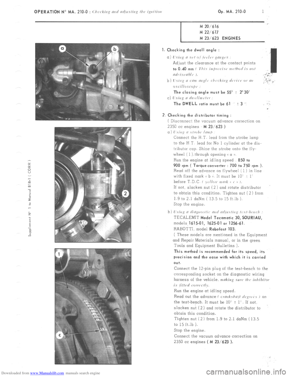
Connect the H.T. lead from the strobe lamp
to the H T lead for No 1 cylinder at the dis-
tributor cop. Shine the strobe onto the fly-
wheel ( 1 ).through opening (( a P)
Run the engine at idling speed 850 +o 900
rpm ( Torque converter : 700 to 7x) rpm ).
Read off the advance on flywheel [ 1 ) in line
with fixed mark (< b 8). It must be 10 i 1
before T.D.C , , <,//or, v,or& S< < /> ,,
If not, slacken nut ( 2 ) and rotate distributor
to ohtoin this condition. Tighten nut (2) from
1.9 to 2.1 daNm ( 13.5 to 15 ft.lb ).
Stop the engine.
b) U.sivR n riin~uo.~~ir m,d od;uc!ir,,~ ~r~c~-lwu~h :
TECALEMIT
Model Tecamatic 30, SOURIAU,
models 1615.01, 1625-01 or 1256.61.
RABOTTI. model Robofast 103.
( These models are mentioned in the Equipment
and Repair Materials manual, OI in the green
Tools and Equipment Bulletins 1.
This method is recommended for its speed, its
precision and the ease with which it is carried
ou+.
Connect the 12-pin plug of the test-bench to the
corresponding socket on the diagnostic wiring
harness of the vehicle. makiug sure the
irrhibifor is litlrd rorwc~ly.
Run the engine at idling speed.
Read out the advance ( rma>rksha// drFwvs , on
the test-bench. It must be lo” + 1:. If not.
slacken nut (2) ond rotate the distributor to
obtain this condition.
Tighten nut (2 1 from 1.9 to 2.1 daNm ( 13.5
to 15 ft.lb 1.
Stop the engine.
Connect the YOCUU~ advance correction on 2350 cc
engines ( M 23/623 ).
Page 157 of 394

Downloaded from www.Manualslib.com manuals search engine 2 OPERATION No MA. 210-O : (.hrrkb,g nnci adiustiug ~hc igrzitim
If CI strobe lamp 01 a diagnosis test bench ore not available. adjusting the distributor timing may be carried out
using LT test lamp. with the engine at static advance point. ( See Chapter III, pages 4 and 5 ).
3. Check the spark regularity :
tisiag n s/robe Imp :
With the distributor timing properly odj.usted ( loi ? 1’ at 850 ?- 50 rpm or 700 ? 50 rpm for torque converter 1,
the advance point must remain within 2”.
1’s;~~ n dinpi,osfir /cs/-hozrh :
The start of opening, or the dwell angle value of the contact breaker ( according to the type of test-bench used )
should not vary by more than 2’ on each boss of the cam.
If this is not the case the rotor clrm 01 the contact breaker bock-plate ore faulty
The distributor must be reconditioned or replaced. II. CHECKING AND ADJUSTING THE DISTRIBUTOR ON A TEST-BENCH
L.21.4 ante LA 2
n Centrifugal adv
Page 158 of 394
Downloaded from www.Manualslib.com manuals search engine OPERATION No MA. 210-O : (.h(~~-ki/lg n~lc/ c~tlj~~s/irtg the igrlitiorl Op. MA. 210-O 3
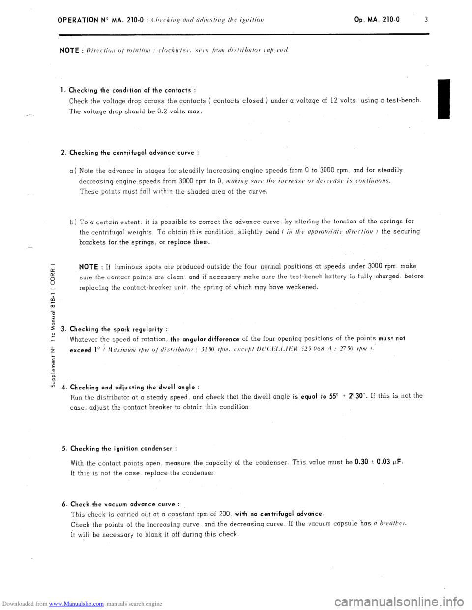
1. Checking the condition of the contacts :
Check the voltage drop across the contacts ( contacts closed ) under a voltage of 12 volts. using a test-bench.
The voltage drop should be 0.2 volts max.
I
2. Checking the centrifugal advance curve :
a) Note the advance in stages for steadily increasing engine speeds from 0 to 3000 rpm. and for steadily
decreasing engine speeds from 3000 rpm to 0, t~/~kjj/$ SII~L’
the irirwasc, or d~,rrc~as~’ is c-o~~ti~ootl.5.
These points must fall within the shaded area of the curve.
b) To a certain extent. it is possible to correct the advance curve, by altering the tension of the springs for
the centrifugal weights To obtain this condition, slightly bend (
iv t/1(, np1)ro/)riotc, ciirectioll J the securing
brackets for the springs, or replace them.
IY NOTE : If luminous spots are produced outside the four normal positions at speeds under 3000 rpm. make
5 sure the contact points are clean and if necessary make sure the test-bench battery is fully charged. before
U replacing the contact-breaker unit. the spring of which may have weakened.
7
co
m
r 3. Checking the spark regularity :
2
Whatever the speed of rotation, the angular difference of the four opening positions of the points must n.ot
3 exceed lo I 21n.xint~lm r/In/ oj distributor : 3250 I./)NI. c,.vcc,pt I)l’(.lit,t.tt~K 525 06X A : 2750
r/m 1,
c
E
!i
a
z 4. Ch k’ ec rng and adjusting the dwell angle :
Run the distributor at a steady speed, and check that the dwell angle is equal ;o 55’ ? 2”30’. If this is not the
case, adjust the contact breaker to obtain this condition.
5. Checking the ignition condenser :
With the contact points open. measure the capacity of the condenser; This value must be 0.30 i 0.03 wF.
If this is not the case. replace the condenser.
6. Check the vacuum advance curve :
This check is carried out at a constant rpm of 200, with no centrifugal advance.
Check the points of the increasing curve. and the decreasing curve. If the vacuum capsule has n hathcr.
it will be necessary to blank it off during this check.
Page 160 of 394
Downloaded from www.Manualslib.com manuals search engine OPERATION No MA. 210.0 : c l~vritis,e nvrl
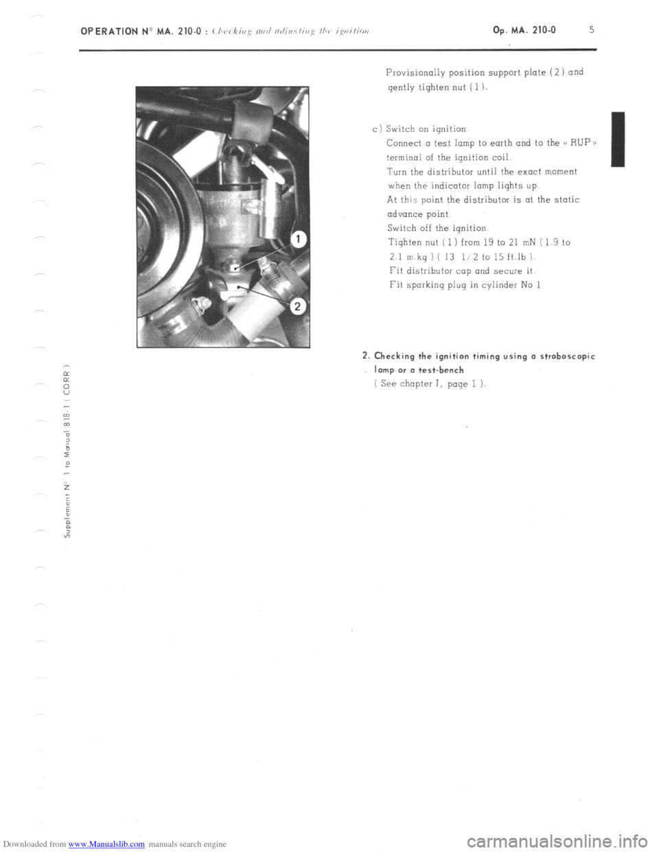
Provisionally position support plate (2 1 and
gently tighten nut ( 1 )
c) Switch on ignition
Connect a test lamp to earth and to the G RUP B)
terminal of the ignition coil.
Turn the distributor until the exact moment
when the indicator lamp liqhts up.
At this point the distributor is al the static
advance point.
Switch off the ignition.
Tighten nut ( 1 ) from 19 to 21 mN ( 1.9 to
2.1 m kq 1 ( 13 l/2 to 15 ft.lb 1.
Fit distributor cap and secure it
Fit sparking plug in cylinder No 1 2. Checking the ignition timing using a stroboscopic
Imp or (I test-bench
( See chapter I,, page 1 i.
Page 161 of 394
Downloaded from www.Manualslib.com manuals search engine OPERATION No MA. 210-O a : C/ ‘CC ,r,,q rind ndj,,s/isp I/W ~~/<~c-/mr,ir ip,itior, 5?‘.5/‘.,11 k’ Op. MA. 210-O a 1
M 23/622 ENGINE
I. CHECKING THE IGNITION OM THE VEHICLE
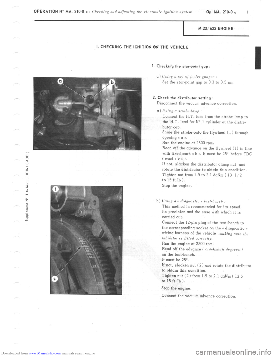
I. Checkin‘g the star-point gap :
a) L’si,,g N se, 0, /vdrr g”,,g”” :
Set the star-point gap to 0 3 to 0.5 mm
2. Check the distributor setting :
Disconnect the vacuum advance correction
a) L’sing 0 s/,uh‘4n,,,,p :
Connect the H.T. lead from the strobe-lamp to
the H.T. lead for N3 1 cylinder at the distri-
butor cap.
Shine the strobeonto the flywheel (1 1 through
opening e a 1).
Run the engine at 2500 rpm.
Read off the advance on the flywheel (1) in line
with fixed mark SC b )a. It must be 25’ before TDC
f mark x c x ).
If not. slacken the distributor clomp nut. and
rotate the distributor to obtain this condition.
Tighten nut from 1.9 to 2.1 doNm ( 13 1.12
to 15 ft.Ib ).
Stop the engine
b) Usisg n u rlia~,,ms/ir x /rs/.h<~,irh :
This method is recommended for its speed.
its precision and the ease with which it is
carried out.
Connect the 12-pin plug of the test-bench to
the corresponding socket on the G< diagnostic n
wiring harness of the vehicle n,aking sur(, ,h,
iuhihilor is /if/cd corr~~ctly.
Run the engine at 2500 rpm.
Read off the advance (
crawkshn// depws 1
on the test-bench.
It must be 25”.
If not, slacken nut (2 1 and rotate the distributor
to obtain this condition.
Tighten nut (2 1 from 1.9 to 2.1 daNm ( 13.5
to 15 ft.Ib ).
Stop the engine.
Connect the vacuum advance correction.
Page 162 of 394
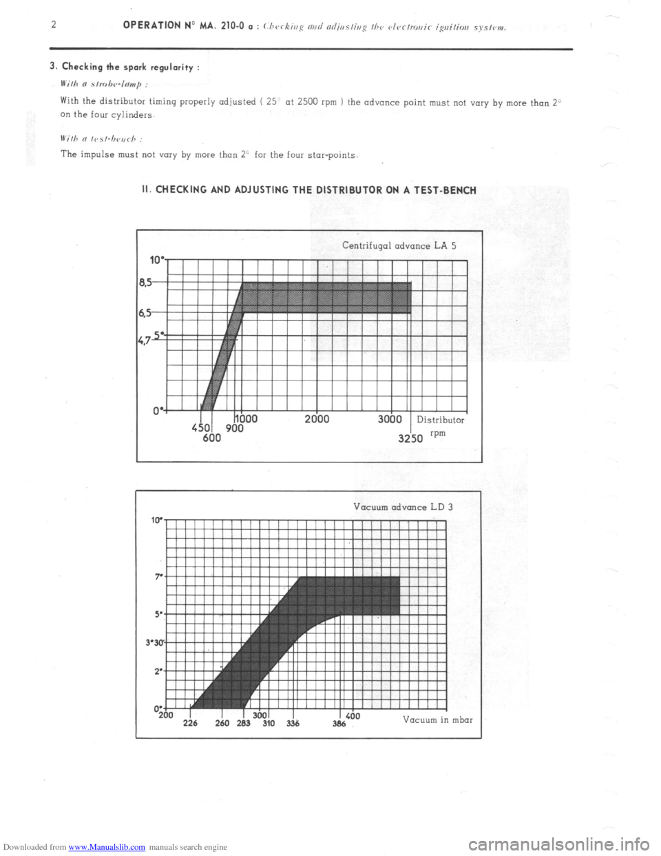
Downloaded from www.Manualslib.com manuals search engine With the distributor timing properly adjusted ( 25’ at 2500 rpm ) the advance point must not vary by more than 2”
on the four cylinders.
IVilh n lvsl.b<~,,rh :
The impulse must not vary by more than 2’ for the four star-points. II. CHECKING AND ADJUSTING THE DISTRIBUTOR ON A TEST-BENCH
Centrifugal advance LA 5
Vacuum advance LD
I -200 226 I 260 I 283 I 3601 310 3% I Vacuum in mbar
Page 163 of 394
Downloaded from www.Manualslib.com manuals search engine OPERATION No MA. 210-O Q : C.‘/)c,r&iug nnrt nrljtlsliug I110 c~t~~clro~~ic igrliliorl sj’slvnv. Op. MA. 210-O a 3
1. Adiust star-point gop : 0.3 to 0.5
mm
2. Check the centrifugal advance curve :
a) Note the advance in stages for steadily increasing engine speeds from 0 to 3000 rpm and for steadily decreasing
engine speeds from 3000 rpm to 0. making sure the increase or decrease is continuous. These points must fall
within the shaded area of the curve.
b ) To a certain extent. it is possible to correct the advance curve. by altering the tension of the springs for the
z centrifugal weights To obtain this condition slightly bend (
irr I~V nppropriate clirvcliou ) the securing brackets
6 for the springs. or replace them.
ot,
43
a
3
E
E 3. Checking the symmetry of the star-points :
-z
0
IFi
The angular positioning of the 4- star-points must be the same to within 1”. whatever the speed of the engine.
4. Checking the vacuum advance curve :
This check is carried out at a constant 200 rpm. with no centrifugal advance.
Check the points for the increasing curve, then the decreasing curve.
If the vacuum capsule has a breather, it will be necessary to blank it off during the’test.