engine Citroen CX 1981 1.G Workshop Manual
[x] Cancel search | Manufacturer: CITROEN, Model Year: 1981, Model line: CX, Model: Citroen CX 1981 1.GPages: 394
Page 131 of 394
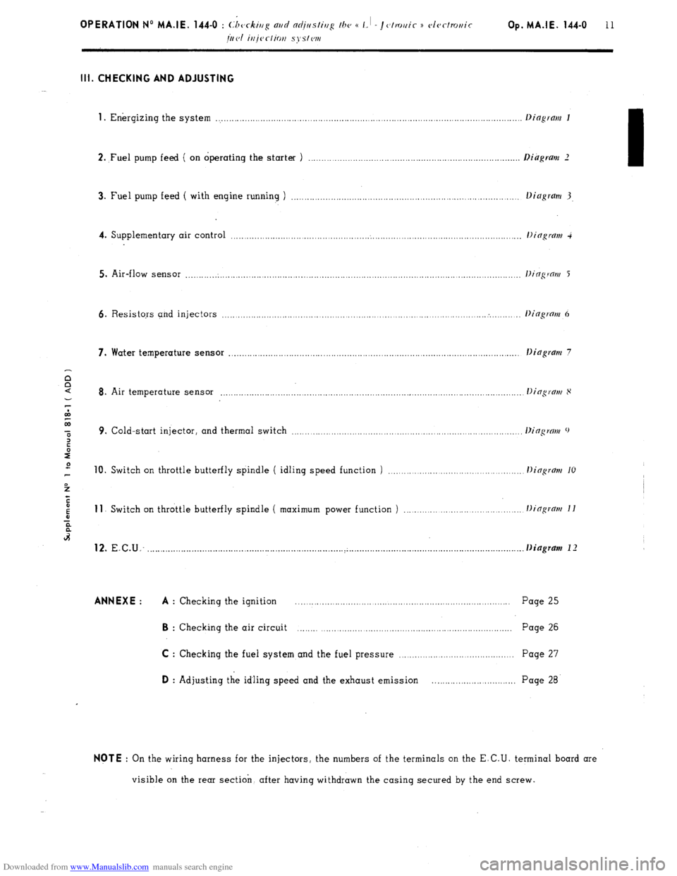
Downloaded from www.Manualslib.com manuals search engine Ill. CHECKING AND ADJUSTING
1
. Energizing the system ..................................................................................................................
2. ,Fuel pump feed ( on operating the starter ) .............................................................................
3. Fuel pump feed ( with engine running ) ...................................................................................
4. Supplementary air control ...........................................................................................................
5. Air-flow sensor ............................................................................................................................
6. Resistors and injectors ................................................................................................... . ........
7. Water temperature sensor ............................................................................................................ .
Dingram 7
8. Air temperature sensor ...............................................................................................................
9. Cold-start injector, and thermal switch ...................................................................................
10. Switch on throttle butterfly spindle ( idling speed function ) ............................................ 11
Switch on throttle butterfly spindle ( maximum power function ) ...................................... 12.
E.C.U: ......................................................................... ..~ ............................................................... . . Diagram 1 I ANNEXE : A
: Checking the ignition .................................................................................. Page 25 B
: Checking the air circuit ................................................................................ Page 26
C : Checking the fuel system and the fuel pressure ........................................... Page 27 D
: Adjusting the idling speed and the exhaust emission .............................. Page 28 NOTE
: On the wiring harness for the injectors, the numbers of the terminals on the E.C.U. terminal board are
visible on the rear section. after having withdrawn the casing secured by the end screw.
Page 132 of 394
Downloaded from www.Manualslib.com manuals search engine 1. Energizing the system : ( DIAGRAM 1 )
_ Disconnect the E.C U
- Switch the ignition on
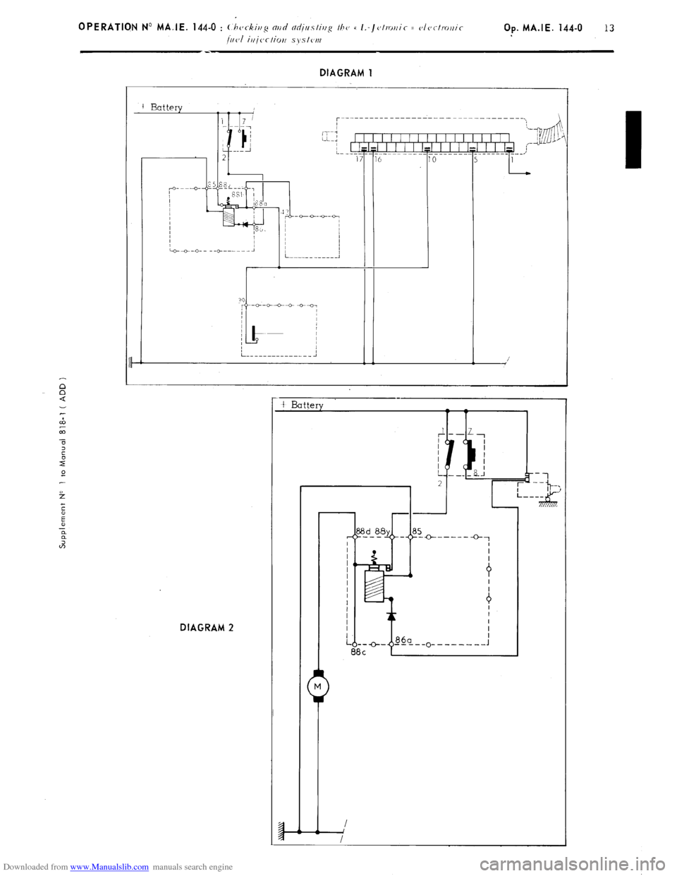
Using a voltmeter. ensure that each point in
dingrm 1 is effectively energised. after having tested the
earthing. If not, switch off the ignition. and test the circuit using a battery operated ohmmeter. With the
voltmeter connected between terminals ( 1 ) and ( 5) of the E. C.U., operate the starter the voltmeter must
register the ignition impulses If it does not. check the ignition
( ANNEXE A ).
2. Fuel pump feed ( on operating the starter ) ( DIAGRAM 2 )
- Disconnect the E C.U.
- Switch on the ignition
- On operating the starter. the fuel pump (
secureri rrt/rler the I c~hiclc’. uoor IIJO K. ti. ronr (, l~eol I must be
heard to operate by someone standing close by
If not switch off the ignition, and test the circuit using a battery operated ohmmeter.
The resistance between terminal (( 88 d H of the relay assembly ( c~r~tler 111~
L,H. honr/llor)~p ) and earth
must be 1 Q approx-
Make sure the petrol pump is properly earthed.
Page 133 of 394
Downloaded from www.Manualslib.com manuals search engine f
E
E
a
a
2 DIAGRAM 1
I t
5 E 0
t-
DIAGRAM 2 /
-
t Battery +-----
0-1
Page 134 of 394

Downloaded from www.Manualslib.com manuals search engine DIAGRAM 3
+ Battery
:------------ ____ -----_---------- -------- -A---\,
+fi ,c
i!J &J
/---I - 0
___,’
DIAGRAM 4
Page 135 of 394
Downloaded from www.Manualslib.com manuals search engine Op. MA.IE 444-O 15
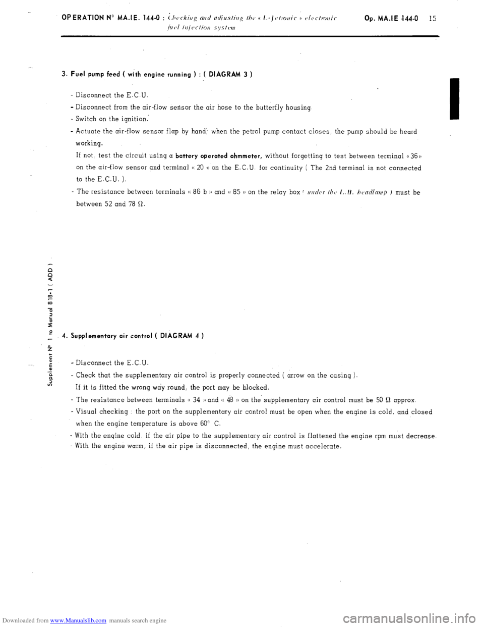
3. Fuel pump feed ( with engine running ) : ( DIAGRAM 3 )
- Disconnect the E.C.U.
- Disconnect from the air-flow sensor the air hose to the butterfly housing
- Switch on the ignition:
- Actuate the air-flow sensor flap by hand’ when the petrol pump contact closes the pump should be heard
working.
If not, test the circuit using a
battery operated ohmmeter, without forgetting to test between terminal G 36 ))
on the air-flow sensor and terminal H 20 .)) on the E.C.U. for continuity ( The 2nd terminal is not connected
to the E.C.U. ).
- The resistance between terminals (( 86 b H and G 85 )) on the relay box f //j/nor thc~ I~./I. h<~ntllnr~tp ) must be
between 52 and 78 12.
P 4. Supplementary air control ( DIAGRAM 4 )
4
c
5
6
- Disconnect the E.C.U.
-E
? - Check that the supplementary air control is properly connected ( arrow on the casing )~
In
If it is fitted the wrong way round. the port may be blocked.
- The resistance between terminals (( 34 1, and (( 48 )) on the- supplementary air control must be 50 Q approx-
- Visual checking the port on the supplementary air control must be open when the engine is cold, and closed
when the engine temperature is above 60” C
- With the engine cold. if the air pipe to the supplementary air control is flattened the engine rpm must decrease.
With the engine warm, if the air pipe is disconnected, the engine must accelerate.
Page 136 of 394
Downloaded from www.Manualslib.com manuals search engine 5. Air-flow sensor ( DIAGRAM 5 )
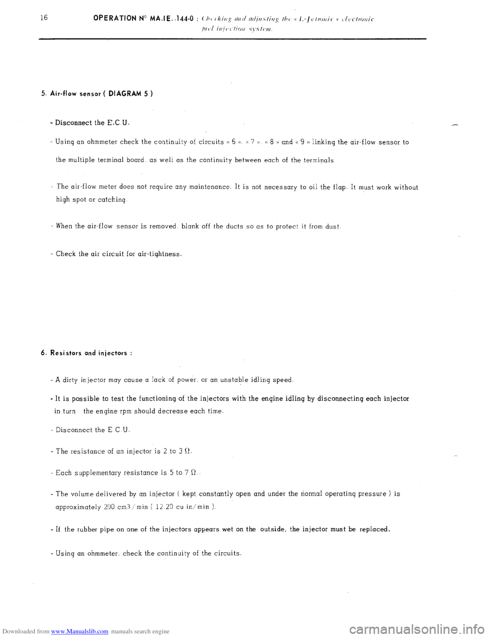
- Disconnect the E.C.U.
- Using an ohmmeter check the continuity of circuits (( 6 )a, H 7 )) (( 8 H and (( 9 )) linking the air-flow sensor to
the multiple terminal board. as well as the continuity between each of the terminals
- The air-flow meter does not require any maintenance. It is not necessary to oil the flop. It must work without
high spot or catching
When the air-flow sensor is removed blank off the ducts so OS to protect it from dust
- Check the air circuit for air-tightness.
6. Resistors and injectors :
- A dirty injector may cause o lock of power. or on unstable idling speed.
- It is possible to test the functioning of the injectors with the engine idling by disconnecting each injector
in turn the engine rpm should decrease each time.
- Disconnect the E C U
- The resistance of an injector is 2 to 3 II.
- Each supplementary resistance is 5 to 7 R
- The volume delivered by an injector ( kept constantly open and under the normal operating pressure ) is
approximately 200 cm3 /min ( 12 25 cu in/min )-
- If the rubber pipe on one of the injectors appears wet on the outside, the injector must be replaced.
- Using an ohmmeter, check the continuity of the circuits
Page 137 of 394

Downloaded from www.Manualslib.com manuals search engine 2 f DIAGRAM 5
(‘
;“--“- -
I
I 1
L _____ ------- ---- J DlAGRAM 6
G----Q-.-O
O-~-C--O
r’
L-----------i
Page 138 of 394

Downloaded from www.Manualslib.com manuals search engine DIAGRAM 7
r----- __ _____ ------- ---------------_
I I
I
“-7
u-j
I I I I I I I I I I I I, I, I, I, I, I I I ( “7 ’ ,-Jg rl\j ’ I I I I=1 I I I I i /
L----.-----J------ _____ --___--------I’
i3 5 DIAGRAM &
I---------- ________ - --------------------,
1
I
27
L ____ ------ ------- 2
Page 139 of 394
Downloaded from www.Manualslib.com manuals search engine 7. Water temperature sensor : ( DIAGRAM 7 )
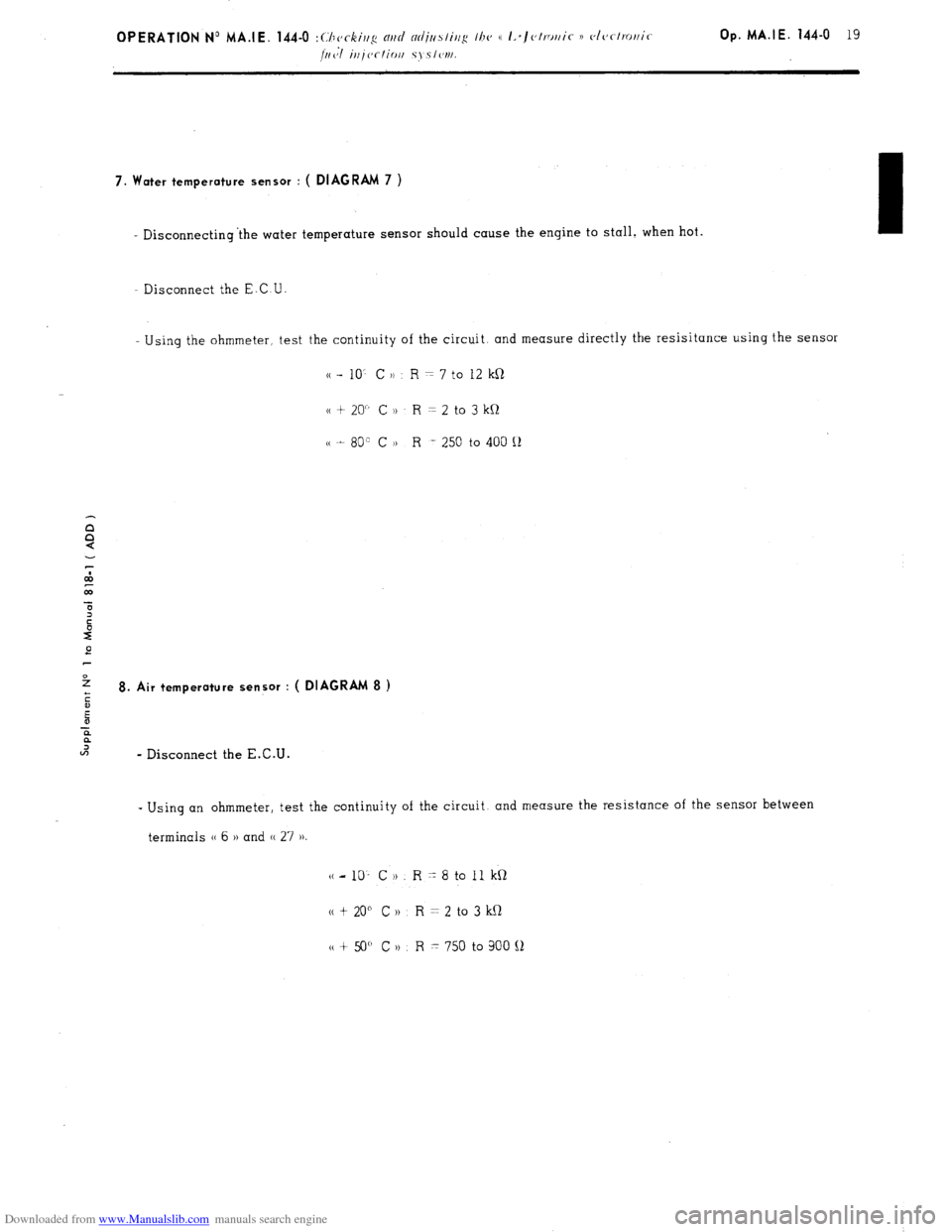
- Disconnecting ‘the water temperature sensor should cause the engine to stall. when hot.
- Disconnect the E.C U
Using the ohmmeter, test the continuity of the circuit. and measure directly the resisitance using the sensor
cc - 10’ C )) R = 7 to 12 kR
cc + 20” C )t R = 2 to 3 kQ
cc t 80” C H R -. 250 to 400 Q
e
2
ii 8. Air temperature sensor : ( DIAGRAM 8 )
E
-E
?
U-J
- Disconnect the E.C.U. -
Using an ohmmeter, test the continuity of the circuit. and measure the resistance of the sensor between
terminals (( 6 )) and (( 27 ))
(c-10’ CH. R-8toIlkQ
N t 20” C 1) R = 2 to 3 kQ
tt + 50” C n R x 750 to 900 !J
Page 140 of 394
Downloaded from www.Manualslib.com manuals search engine 9. Cold-start injector, and thermal switch : ( DIAGRAM 9 )
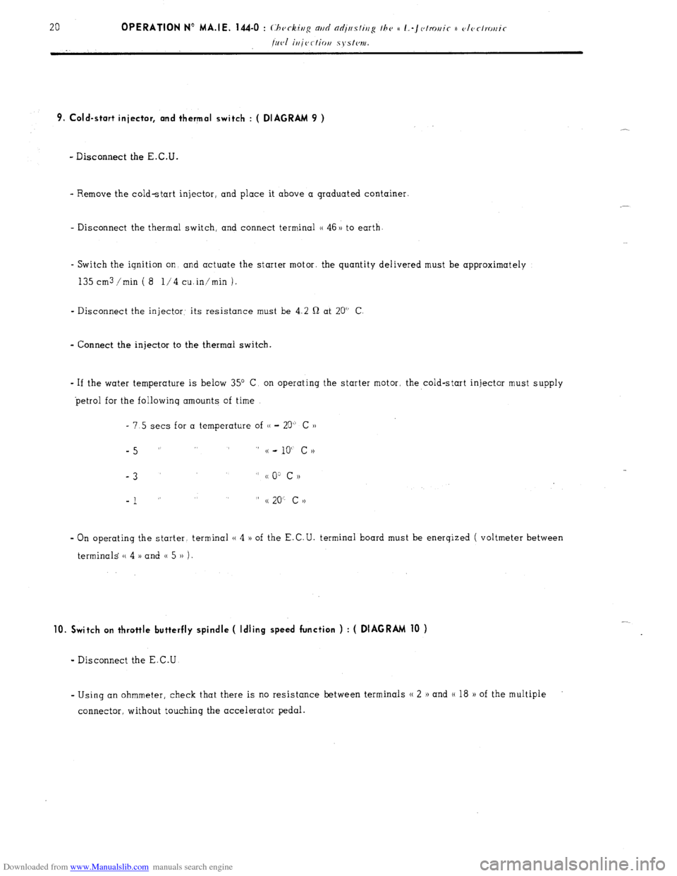
- Disconnect the E.C.U.
- Remove the cold-start injector, and place it above a graduated container.
- Disconnect the thermal switch, and connect terminal (( 46 )) to earth
- Switch the ignition on and actuate the starter motor. the quantity delivered must be approximately
135 cm3 /min ( 8 l/4 cuin’min 1.
- Disconnect the injector: its resistance must be 4.2 Q at 20” C
- Connect the injector to the thermal switch.
- If the water temperature is below 35” C, on operating the starter motor, the cold-start injector must supply
petrol for the followinq amounts of time
- 7.5 sets for a temperature of (( - 20” C ))
-5 ” ” (( - 10“ c N
-3
” cc 0: c ))
-1 ” ” (( 20” c >)
- On operating the starter. terminal (( 4 )) of the E.C.U. terminal board must be enerqized ( voltmeter between
terminals (( 4 )) and 0 5 )) 1.
10. Switch on throttle butterfly spindle ( Idling speed function ) : ( DIAGRAM 10 )
- Disconnect the E.C.U
- Using an ohmmeter, check that there is no resistance between terminals N 2 H and (( 18 H of the multiple
connector, without touching the accelerator pedal.