engine Citroen CX 1981 1.G Workshop Manual
[x] Cancel search | Manufacturer: CITROEN, Model Year: 1981, Model line: CX, Model: Citroen CX 1981 1.GPages: 394
Page 161 of 394
Downloaded from www.Manualslib.com manuals search engine OPERATION No MA. 210-O a : C/ ‘CC ,r,,q rind ndj,,s/isp I/W ~~/<~c-/mr,ir ip,itior, 5?‘.5/‘.,11 k’ Op. MA. 210-O a 1
M 23/622 ENGINE
I. CHECKING THE IGNITION OM THE VEHICLE
I. Checkin‘g the star-point gap :
a) L’si,,g N se, 0, /vdrr g”,,g”” :
Set the star-point gap to 0 3 to 0.5 mm
2. Check the distributor setting :
Disconnect the vacuum advance correction
a) L’sing 0 s/,uh‘4n,,,,p :
Connect the H.T. lead from the strobe-lamp to
the H.T. lead for N3 1 cylinder at the distri-
butor cap.
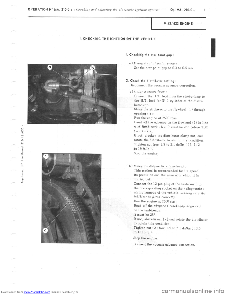
Shine the strobeonto the flywheel (1 1 through
opening e a 1).
Run the engine at 2500 rpm.
Read off the advance on the flywheel (1) in line
with fixed mark SC b )a. It must be 25’ before TDC
f mark x c x ).
If not. slacken the distributor clomp nut. and
rotate the distributor to obtain this condition.
Tighten nut from 1.9 to 2.1 doNm ( 13 1.12
to 15 ft.Ib ).
Stop the engine
b) Usisg n u rlia~,,ms/ir x /rs/.h<~,irh :
This method is recommended for its speed.
its precision and the ease with which it is
carried out.
Connect the 12-pin plug of the test-bench to
the corresponding socket on the G< diagnostic n
wiring harness of the vehicle n,aking sur(, ,h,
iuhihilor is /if/cd corr~~ctly.
Run the engine at 2500 rpm.
Read off the advance (
crawkshn// depws 1
on the test-bench.
It must be 25”.
If not, slacken nut (2 1 and rotate the distributor
to obtain this condition.
Tighten nut (2 1 from 1.9 to 2.1 daNm ( 13.5
to 15 ft.Ib ).
Stop the engine.
Connect the vacuum advance correction.
Page 162 of 394
Downloaded from www.Manualslib.com manuals search engine With the distributor timing properly adjusted ( 25’ at 2500 rpm ) the advance point must not vary by more than 2”
on the four cylinders.
IVilh n lvsl.b<~,,rh :
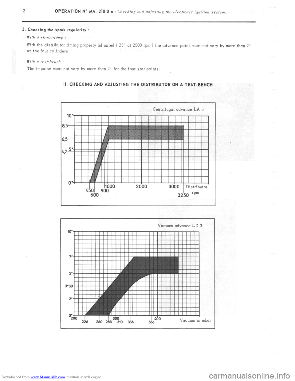
The impulse must not vary by more than 2’ for the four star-points. II. CHECKING AND ADJUSTING THE DISTRIBUTOR ON A TEST-BENCH
Centrifugal advance LA 5
Vacuum advance LD
I -200 226 I 260 I 283 I 3601 310 3% I Vacuum in mbar
Page 163 of 394
Downloaded from www.Manualslib.com manuals search engine OPERATION No MA. 210-O Q : C.‘/)c,r&iug nnrt nrljtlsliug I110 c~t~~clro~~ic igrliliorl sj’slvnv. Op. MA. 210-O a 3
1. Adiust star-point gop : 0.3 to 0.5
mm
2. Check the centrifugal advance curve :
a) Note the advance in stages for steadily increasing engine speeds from 0 to 3000 rpm and for steadily decreasing
engine speeds from 3000 rpm to 0. making sure the increase or decrease is continuous. These points must fall
within the shaded area of the curve.
b ) To a certain extent. it is possible to correct the advance curve. by altering the tension of the springs for the
z centrifugal weights To obtain this condition slightly bend (
irr I~V nppropriate clirvcliou ) the securing brackets
6 for the springs. or replace them.
ot,
43
a
3
E
E 3. Checking the symmetry of the star-points :
-z
0
IFi
The angular positioning of the 4- star-points must be the same to within 1”. whatever the speed of the engine.
4. Checking the vacuum advance curve :
This check is carried out at a constant 200 rpm. with no centrifugal advance.
Check the points for the increasing curve, then the decreasing curve.
If the vacuum capsule has a breather, it will be necessary to blank it off during the’test.
Page 164 of 394
Downloaded from www.Manualslib.com manuals search engine 4 OPERATION No MA. 210-O o : (./wrkh,i: rind nrlj,,s/inp /hc rlvr/,riai< igvi,io,, ~YS/C,,,,.
II;. FITTING THE DISTRIBUTOR ONTO THE VEHICLE
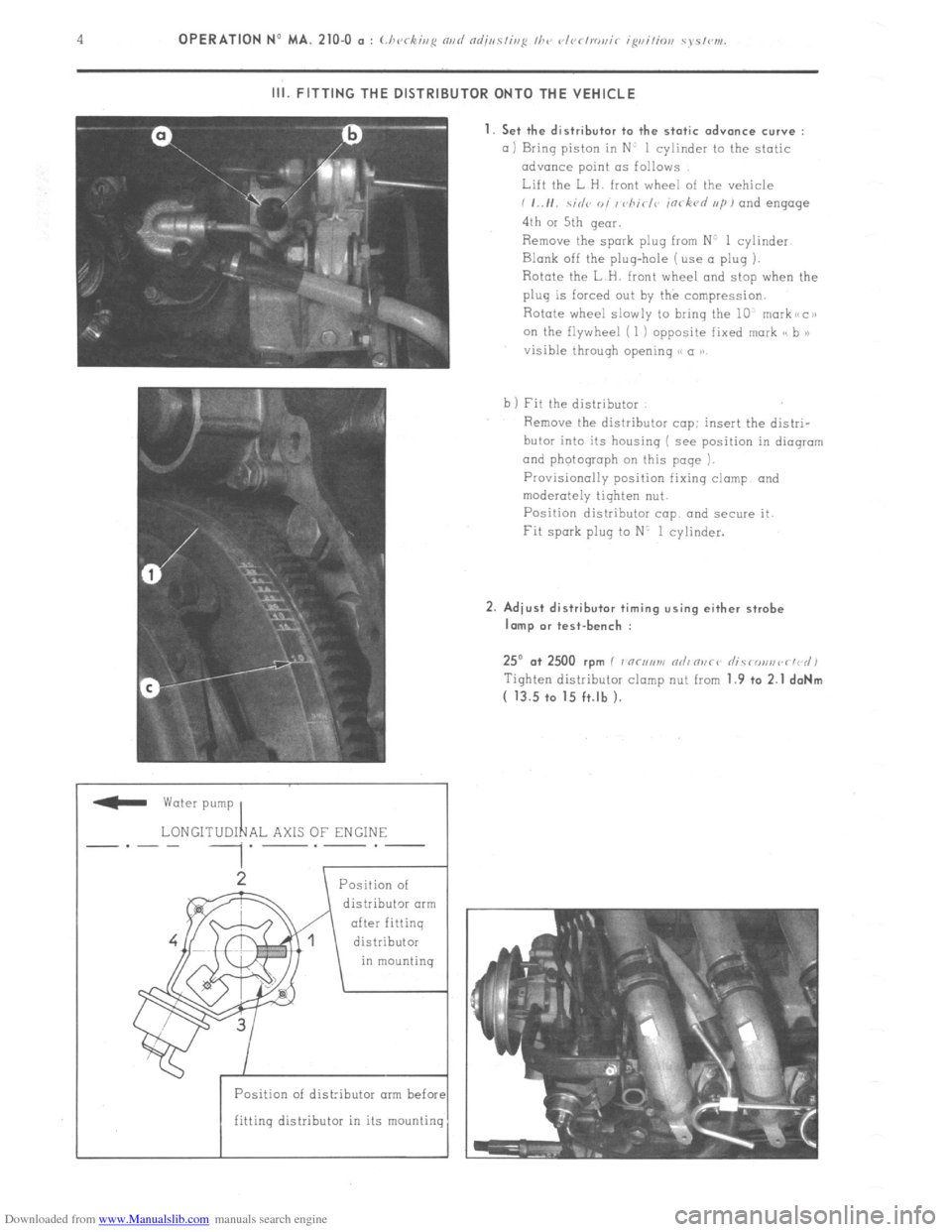
_ water pump
LONGITUDI 1 AL AXlS OF ENGINE
.-.-.-
distributor arm
Position of dist:ibutor arm befol
fitting distributor in its mountin 1. Set the distributor to the static advance curve :
a) Bring piston in N’ 1 cylinder to the static
advance point LTS follows
Lift the L H. front wheel of the vehicle
i ,..I,. .\;,I<~ o, / vhirl<~ in< kvd ,,/I, and engage
4th or 5th qeor.
Remove the spark plug from N’ 1 cylinder
Blank off the plug-hole (use a plug ).
Rotate the L H. front wheel and stop when the
plug is forced out by the compression.
Rotate wheel slowly to bring the 10, markiicai
on the flywheel ( 1 ) opposite fixed mark cs b >)
visible throuqh opening S< a ))
b 1 Fit the distributor
Remove the distributor cop: insert the distri-
butor into its housing ( see position in dioqrom
and photograph on this page ).
Provisionally position fixing clamp and
moderately tighten nut.
Position distributor cap and secure it.
Fit spark plug to N’ 1 cylinder. 2. Adiust distributor timing using either strobe
lamp or test-bench :
25” .a+ 2500 rpm I 7 “c,,,m nrli n,,ci’ rlicronsvr~d)
Tiqhten distributor clomp nut from 1.9 +o 2.1 daNm
( 13.5 to 15 ft.lb ).
Page 165 of 394
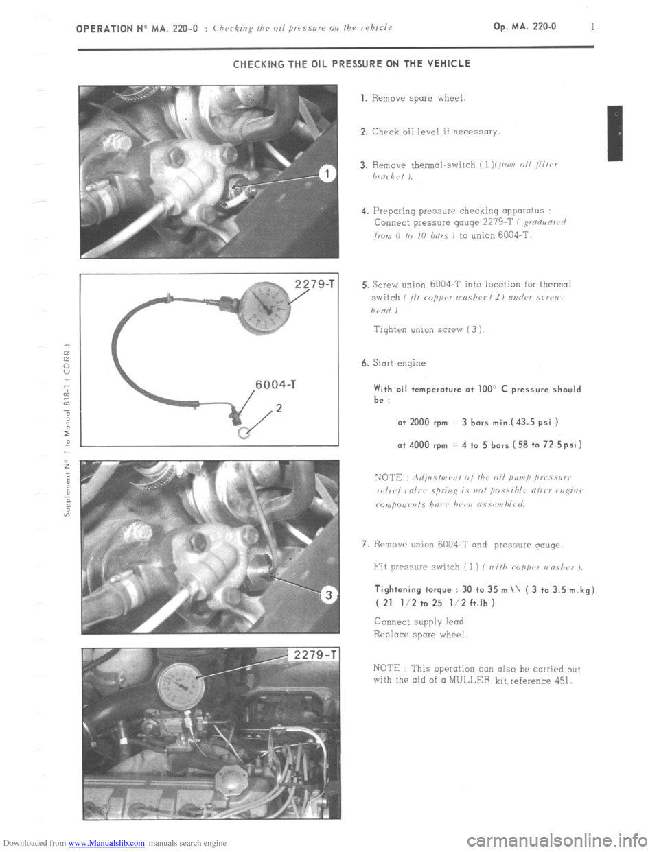
Downloaded from www.Manualslib.com manuals search engine OPERATION No MA. 220-O : (.hrrkinfi Ih e oil pr~ssrrrc m the rehicle Op. MA. 220.0 1
CHECKING THE OIL PRESSURE ON THE VEHICLE
79-T 1. Remove spare
wheel.
2. Check oil level if necessary.
4. Preparing pressure checking apparatus
Connect pressure gauge 2279-T ( ,wdun/r~l
imn 0 /o IO hnrs 1 to union 6004-T.
Tiqhten union screw ( 3 )
6. Start engine With oil temperature at 100’ C pressure should
be :
a+ 2000 rpm 3 bars mini43.5 psi ) o+ 4000 rpm 4 to 5 bars (58 to 72.5psi)
7. Rrmave union 6004-T and pressure qouqe. Tightening torque : 30 to 35 m \ ( 3 to 3.5 m.kg)
( 21 l/2 to 25 l/2 ft.lb )
Connect supply lead
Replace spare wheel
NOTE This operation con also be carried out
with the aid of CI MULLER kit,reference 451.
Page 166 of 394
Downloaded from www.Manualslib.com manuals search engine Op. MA. 221-O I
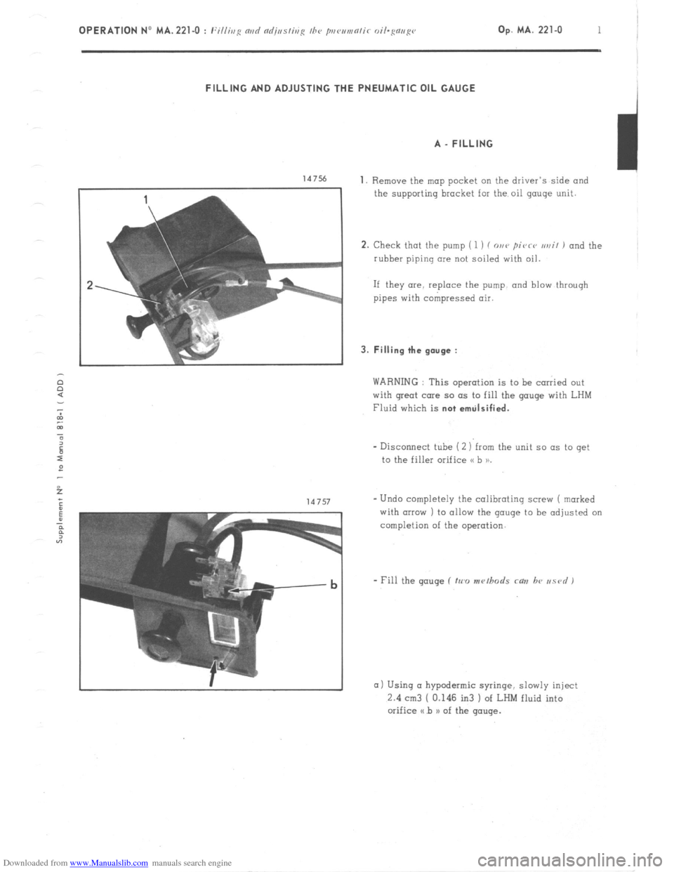
FILLING AND ADJUSTING THE PNEUMATIC OIL GAUGE
A _ FILLING
147% 1. Remove the map pocket on the driver’s side and
the supporting bracket for the oil gauge unit.
2. Check that the pump ( 1 ) f o,,v pivrv ur,il 1 and the
rubber piping clue not soiled with oil.
If they are. replace the pump. and blow through
pipes with compressed air. 3. Filling the gauge :
WARNING : This operation is to be carried out
with great care so as to fill the gauge with LHM
Fluid which is not emtilsified.
- Disconnect tube (2 ) from the unit so as to get
to the filler orifice o b 11.
- Undo completely the calibrating screw ( marked
with (IIPXJ ) to allow the gauge to be adjusted on
completion of the operation.
a) Using CI hypodermic syringe. slowly inject
2.4 cm3 [ 0.146 in3 ) of LHM fluid into
orifice a b n of the gauge.
Page 167 of 394
Downloaded from www.Manualslib.com manuals search engine a
/
/
;X.O3.294.01 A
b
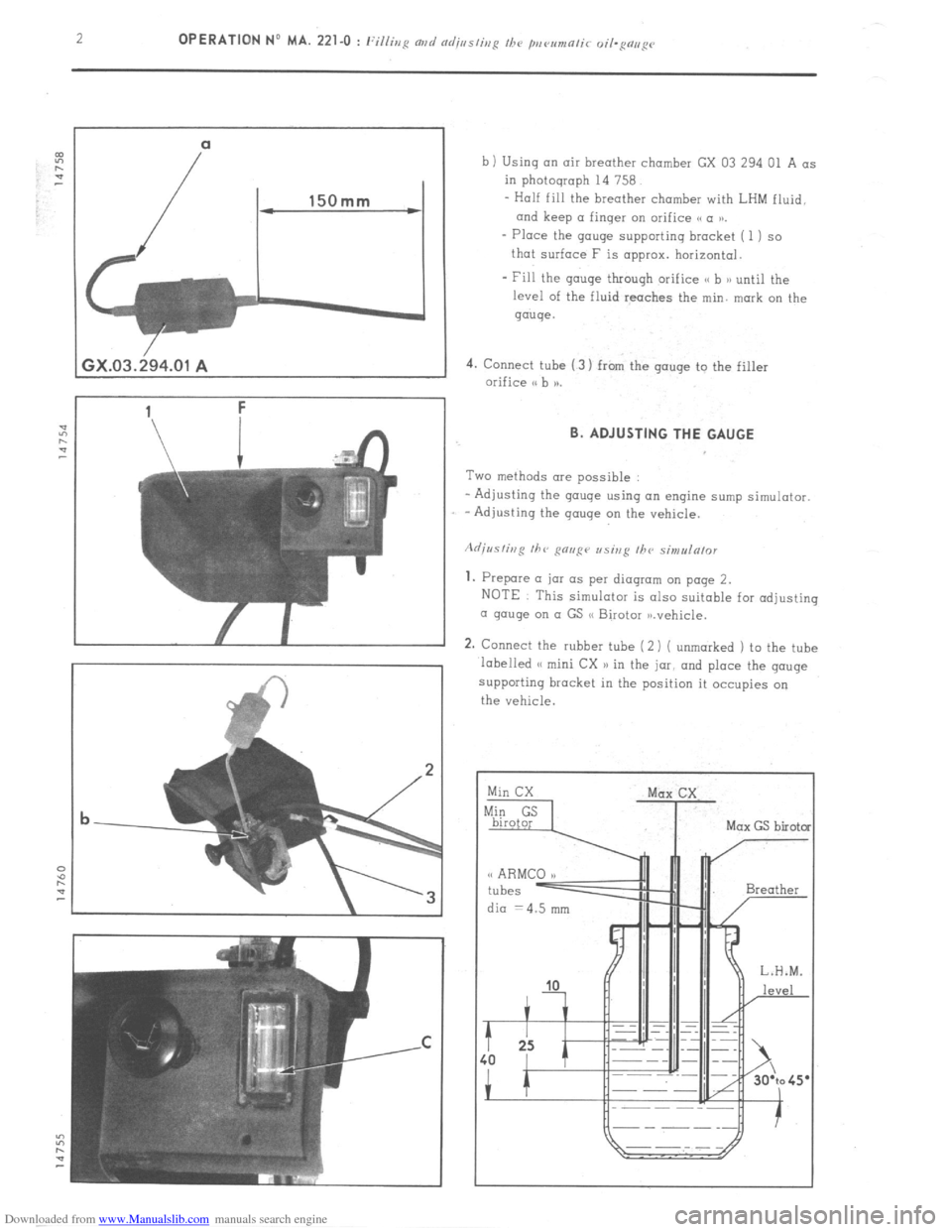
b ) Using an air breather chamber GX 03 294 01 A as
in photograph 14 758.
- Half fill the breather chamber with LHM fluid.
and keep (I finger on orifice (S a tn.
- Place the gouge supporting bracket ( 1) so
that surface F is approx. horizontal.
- Fill the gauge through orifice <( b n until the
level of the fluid reaches the min. mark on the
gauge.
4. Connect tube (3) from the gouge to the filler
orifice I. B. ADJUSTING THE GAUGE
Two methods ore possible
- Adjusting the gouge using an engine sump simulator.
-Adjusting the gauge on the vehicle.
1. Prepare (I jar as per diagram on page 2.
NOTE This simulator is also suitable for adjusting
a gouge on o GS (S Birotor ,n.vehicle.
2. Connect the rubber tube (2 i ( unmarked 1 to the tube
labelled (< mini CX n in the jar, and place the gouge
supporting bracket in the position it occupies on
the vehicle.
dia =4.5 mm
Page 168 of 394
Downloaded from www.Manualslib.com manuals search engine Op. MA. 221-O 3 -
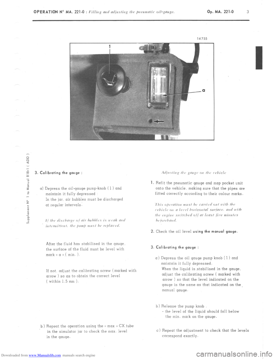
5 3. Calibrating the gouge :
”
6
I
a) Depress the oil-gouge pump-knob i 1) and
:
maintain it fully depressed
f In the jar. air bubbles must be discharged
; at regular intervals.
:
u
P
F
“3 , , ,hr ,I;.7 rhorg<~ ,, I nir hn hhlcs is I, vnk rind
;,,,<,r,,,i,,l~r,,. the primp m,, 51 hl, rcplnrl~d.
After the fluid has stabilised in the gauge
the surface of the fluid must be level with
mark o a a) ( min. i-
If not. adjust
the calibrating screw (marked with
(IIIOW ) so as to obtain the correct level
( within 1.5 mm 1.
b ) Repeot the operation using the << max a) CX tube
in the simulotar jar to check the max. level
in the gauge. 3. Calibrating the gauge :
a) Depress
the oil qauqe pump knob ( 1 1 and
maintain it fully depressed.
When the liquid is stabi!ised in the gouge,
adjust the calibrating screw 1 marked with
arrow ) so that the level indicated on the gauge
is the same as that indicated on the
manual gauge.
b) Release the pump knob
- the level of the liquid should fall below
the min. mark on the gauge.
c) Repeat the adjustment to check that the levels
correspond exactly.
Page 169 of 394
Downloaded from www.Manualslib.com manuals search engine COOLING
Op. MA. 230-00
1
I
Page 170 of 394
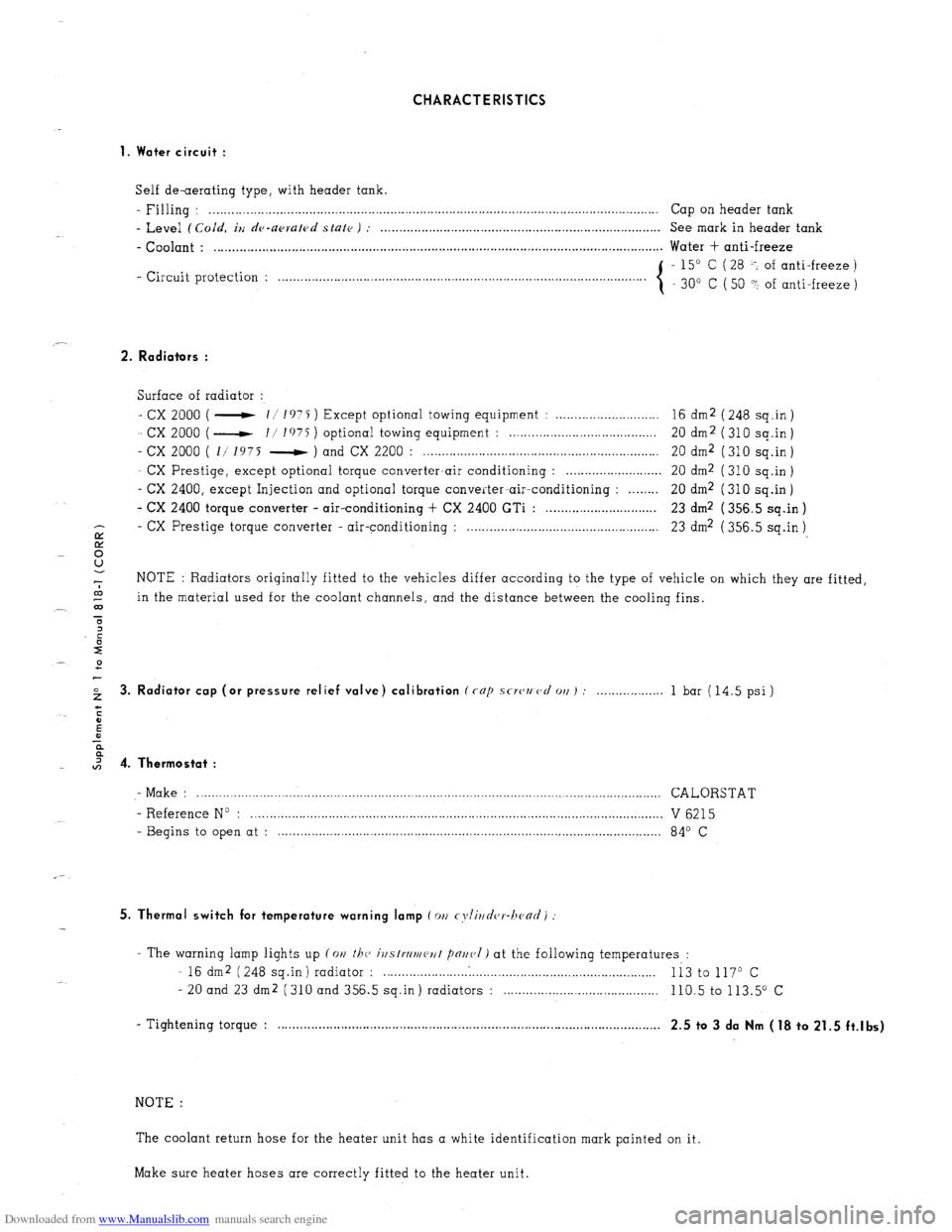
Downloaded from www.Manualslib.com manuals search engine CHARACTERISTICS
1. Water circuit :
Self de-aerating type, with header tank.
- Filling : . . . . . . . .._................................................................................................................ Cap on header tank
- Level (Cold, iu de-upruled state ) : . . . . . . . . . . . . . . . . . . . . . . . . . . . . . . . . . . . . . . . . . . . . . . . . . . . . . . . . . . . . . . . . . . . . . . . . . . . . See mark in header tank
- Coolant : . . . . . . . . . . . . . . . . . . . . . . . . . . . . . . . . . . . . . . . . . . . . . . . . . . . . . . . . . . . . . . . . . . . . . . . . . . . . . . . . . . . . . . . . . . . . . . . . . . . . . . . . . . . . . . . . . . . . . . . . .. Water + anti-freeze
- Circuit protection : - 15” C ( 28 -: of anti-freeze )
. . . . . . . . . . . . . . . . . . . . .
30” C ( 50 ? of anti-freeze )
2. Radiators :
Surface of radiator :
- cx 2000 ( - 11 1975 ) Except optional towing equipment : . . . . . . . . . . . . . . . . . . . . . . . . . . . . 16 dm2 ( 248 sq.in )
- cx 2000 ( - I/ I’)75 ) optional towing equipment : . . . . . . . . . . . . . . . . . . . . . . . . . . . . . . . . . . . . . . 20 dm2 (310 sq.in)
- cx 2000 ( 1/ 1975 - ) and CX 2200 : . . . . . . . . . . . . . . . . . . . . . . . . . . . . . . . . . . . . . . . . . . . . . . . . . . . . . . . . . . . . . . . . 20 dm2 ( 310 sq.in )
- CX Prestige, except optional torque converter-air conditioning : . . . . . . . . . . . . . . . . . . . . . . . . . . 20 dm2 ( 310 sq.in )
- CX 2400, except Injection and optional torque converter-air-conditioning : . . . . . . . . 20 dm2 (310 sq.in)
- CX 2400 torque converter - air-conditioning + CX 2400 GTi : . . . . . . . . . . . . . . . . . . . . . . . . . . . . . . 23 dm2 ( 356.5 sq.in )
- CX
E Prestige torque converter - air-conditioning : . . . . . . . . . . . . . . . . . . . . . . . . . . . . . . . . . . . . . . . . . . . . . . . . . . . . 23 dm2 ( 356.5 sq.in )
8
-7 NOTE : Radiators originally fitted to the vehicles differ according to the type of vehicle on which they are fitted,
co
_- 03 in the material used for the coolant channels, and the distance between the cooling fins.
T
2 3. Radiator cap (or pressure relief valve) calibration (rap scwzmcl 011) : . . . 1 bar (14.5 psi)
I 4. Thermostat :
- Make : .............................................................................................................................. CALORSTAT
- Reference No : ................................................................................................................ V 6215
- Begins to open at : ........................................................................................................ 84’ C
5. Thermal switch for temperature warning lamp (011 cyli~~d(,r-hc~ad)
- The warning lamp lights up (on the, ivstrrlmeut pnr~(,I) at the following temperatures :
- 16 dm2 (248 sq.in) radiator : . . . . . . . . . . . . .
Ii3 to 117O c
- 20 and 23 dm2 (310 and 356.5 sq.in) radiators : . . . . 110.5 to 113.5” c
- Tightening torque : . . . . . . . . . . . . . . . . . . . . . . . . . . . . . . . . . . . . . . . . . . . . . . . . . . . . . . . . . . . . . . . . . . . . . . . . . . . . . . . . . . . , . . . . . . . . . . . . . . . . . . . .
2.5 to 3 da Nm (18 to 21.5 ft.lbs)
NOTE :
The coolant return hose for the heater unit has a white identification mark painted on it.
Make sure heater hoses are correctly fitted to the heater unit.