lock Citroen CX 1981 1.G User Guide
[x] Cancel search | Manufacturer: CITROEN, Model Year: 1981, Model line: CX, Model: Citroen CX 1981 1.GPages: 394
Page 112 of 394
Downloaded from www.Manualslib.com manuals search engine OPERATION No MA.IE. 144-00 : Chnract~~ristics o/ the H I,-jctrortic P dectrnr~ir
/i/c,1 iujcctim splcm. Op. MA.IE. 144-00 17
SUPPLEMENTARY AIR CONTROL ( 1 ) :
I’ / -...’ , _, ._,, ! .’ ! . .
At idling speed and when cold, the engine must produce more torque so as to counteract increased resistance
caused by friction. In addition to an enriched air fuel mixture, the engine also needs, when starting from cold
and during the warming-up period, to be supplied with supplementary air. The E.C.U. compensates for this
supplementary air by providing more fuel; the engine therefore has a larger amount of mixture at its disposal
to reach normal running temperature. The supplementary air control fitted in parallel with the throttle butterfly
supplies the supplementary air. The supplementary air control is heated only when the engine is running, and
its heater winding is supplied electrically as long as the ignition is switched on.
The location of the supplementary air control ‘on the engine block was selected for its good heat transfer charac-
teristics, and so as to subject the unit to the changing ambient temperature of the engine.
The opening section of the supplementary air control is automatically .adjusted according to the temperature, so
that the required idling speed is maintained regardless of engine temperature. When the latter increases, the air
channel is gradually reduced, until it is completely closed when the coolant temperature reaches approximately
+ 60” C. ->.:.. .-. : --.
,
The supplementary air control is situated at a representative spot fo.r engine running temperature. A bi-metal
spring actuates a rotary valve thereby altering the size of the air passage. Electric heating has the advantage
of allowing the. supplementary air to be adjusted at pre-set times. SWITCH ON THROTTLE BUTTERFLY SPINDLE :
,‘1 3 >_
The switch on the throttle butterfly spindle contains two contacts the idling speed contact, and the.full load contact.
The control contact, which.slides along a slot, closes the idling speed contact or the full load contact for a given
position of ‘the butterfly. The’ E.C.U. analyses the signals received so as to adjust the duration of injection.
Page 135 of 394
Downloaded from www.Manualslib.com manuals search engine Op. MA.IE 444-O 15
3. Fuel pump feed ( with engine running ) : ( DIAGRAM 3 )
- Disconnect the E.C.U.
- Disconnect from the air-flow sensor the air hose to the butterfly housing
- Switch on the ignition:
- Actuate the air-flow sensor flap by hand’ when the petrol pump contact closes the pump should be heard
working.
If not, test the circuit using a
battery operated ohmmeter, without forgetting to test between terminal G 36 ))
on the air-flow sensor and terminal H 20 .)) on the E.C.U. for continuity ( The 2nd terminal is not connected
to the E.C.U. ).
- The resistance between terminals (( 86 b H and G 85 )) on the relay box f //j/nor thc~ I~./I. h<~ntllnr~tp ) must be
between 52 and 78 12.
P 4. Supplementary air control ( DIAGRAM 4 )
4
c
5
6
- Disconnect the E.C.U.
-E
? - Check that the supplementary air control is properly connected ( arrow on the casing )~
In
If it is fitted the wrong way round. the port may be blocked.
- The resistance between terminals (( 34 1, and (( 48 )) on the- supplementary air control must be 50 Q approx-
- Visual checking the port on the supplementary air control must be open when the engine is cold, and closed
when the engine temperature is above 60” C
- With the engine cold. if the air pipe to the supplementary air control is flattened the engine rpm must decrease.
With the engine warm, if the air pipe is disconnected, the engine must accelerate.
Page 136 of 394
Downloaded from www.Manualslib.com manuals search engine 5. Air-flow sensor ( DIAGRAM 5 )
- Disconnect the E.C.U.
- Using an ohmmeter check the continuity of circuits (( 6 )a, H 7 )) (( 8 H and (( 9 )) linking the air-flow sensor to
the multiple terminal board. as well as the continuity between each of the terminals
- The air-flow meter does not require any maintenance. It is not necessary to oil the flop. It must work without
high spot or catching
When the air-flow sensor is removed blank off the ducts so OS to protect it from dust
- Check the air circuit for air-tightness.
6. Resistors and injectors :
- A dirty injector may cause o lock of power. or on unstable idling speed.
- It is possible to test the functioning of the injectors with the engine idling by disconnecting each injector
in turn the engine rpm should decrease each time.
- Disconnect the E C U
- The resistance of an injector is 2 to 3 II.
- Each supplementary resistance is 5 to 7 R
- The volume delivered by an injector ( kept constantly open and under the normal operating pressure ) is
approximately 200 cm3 /min ( 12 25 cu in/min )-
- If the rubber pipe on one of the injectors appears wet on the outside, the injector must be replaced.
- Using an ohmmeter, check the continuity of the circuits
Page 148 of 394

Downloaded from www.Manualslib.com manuals search engine ANNEXE : C CHECKING THE FUEL CIRCUIT AND PRESSURE
- Remove the cold-start injector ( 1) and carefully
remove its petrol feed pipe.
- Connect pressure gauge ( 2) onto the cold-start
injector petrol line.
- Fit the cold-start injector zmto the manifold.
- Run the engine at idling speed the petrol pressure
must be regulated to 2 bars ( 29 psi ).
- Disconnect the vticuum pipe ( 3 i from the pressure
regulator the regulated pressure must be 2.5 bars
i 36 l/4 psi ).
If one of the readings is incorrect, check condition
of the flexible vacuum pipe for the pressure
regulator. as well as its aspect. If it is satisfactory
replace the pressure requlotor after making sure
that its VCICUU~ pipe is not blocked totally or
partially at the manifold end.
With the engine stopped, the pressure must
remain stable at 2 bars ( 23 psi ); if not, check
for a leak which could be found at the cold-start
injector, one of the main injectors. or at the level
of the pressure regulator valve diaphragm.
Page 152 of 394
Downloaded from www.Manualslib.com manuals search engine IGNITION
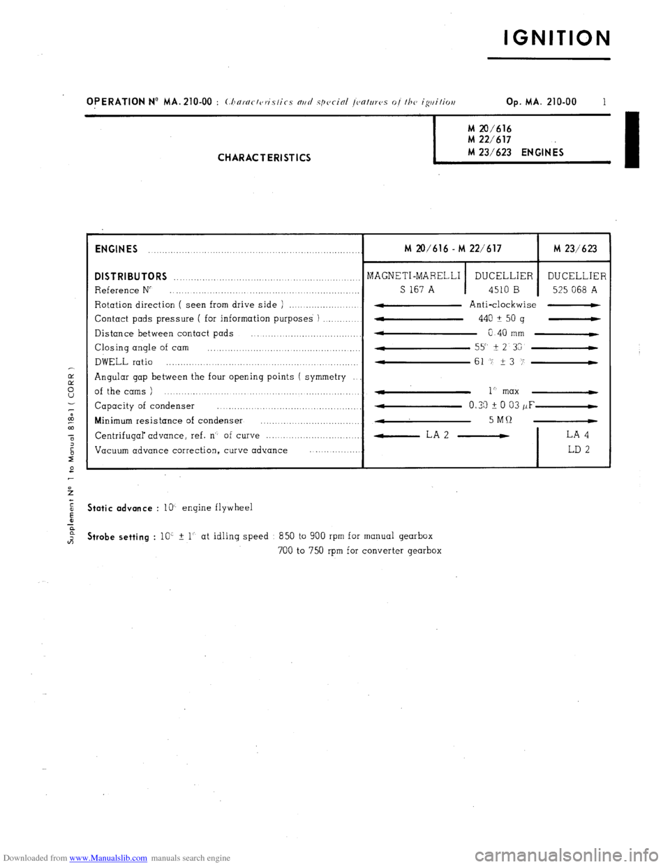
OPERATION N’ MA. 210-00 : (:horr/r/c,ri.s/ics nrtrl spccinl /C,O/UTCJS of /he igtti/ioe Op. MA. 210-00 1 M 20/616
M 22/617 M 23/623 ENGINES
I CHARACTERISTICS
ENGINES
........ ........... ................................................. M 20/616 - M 22/617 M 23/623
DISTRIBUTORS ........................................... MAGNETI-MARELLI _._ ..............
DUCELLIER DUCELLIER
Reference N” ........................... .., ............................. _._ S 167 A 4510 B 525 068 A
Rotation direction ( seen from drive side ) ....................... 4 Anti-clockwise -
Contact pads pressure ( for information purposes ) ..............
w 440 A
50 g -
Distance between contact pads
* ................................... 0 40 mm C
Closing angle of cam ................... .................................. 55" It
2 3G
DWELL ratio ............................................... 4
....... .......... 61 -7 23 i’-
Angular gap between the four opening points ( symmetry
of the cams ) ....................................................... - 1” max 4
Capacity of condenser ......... ... ............... ...... ........ 4 0.33 i 0 03 /IF-
Minimum resistance of condenser ...............................
., ...
4 5MQ -
Centrifugal advance, ref. n’- of curve ................................. -LA2 - LA 4
Vacuum advance correction, curve advance ..................
LD 2 Static advance
: lo’- engine flywheel Strobe setting
: 10’ % 1’. at idling speed 850 to 900 rpm for manual gearbox
700 to 750 rpm for converter gearbox
Page 155 of 394
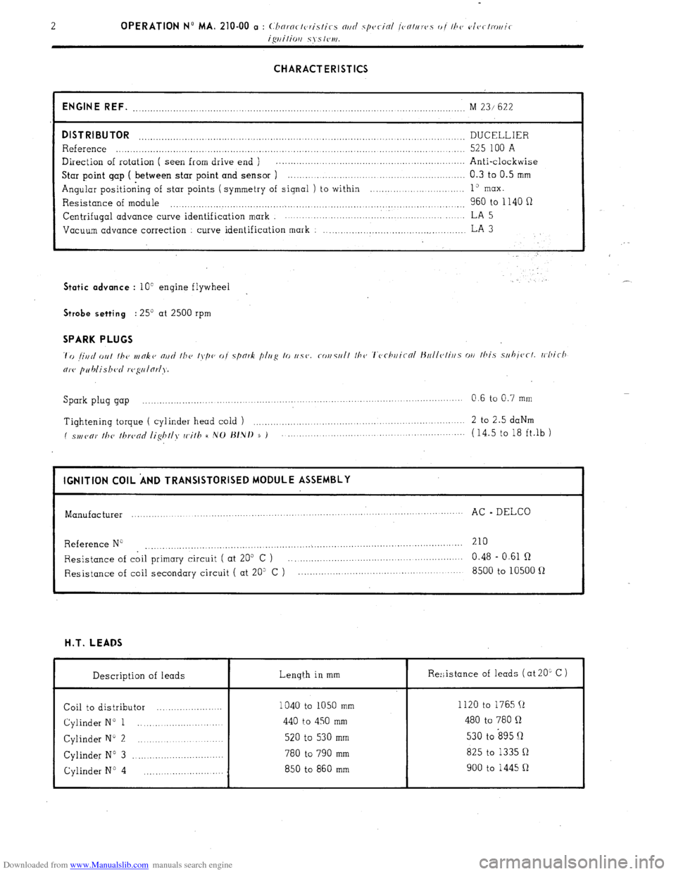
Downloaded from www.Manualslib.com manuals search engine CHARACTERISTICS
ENGINE REF.
........................................................................................... ........................ M 23/ 622
DISTRIBUTOR DUCELLIER ..................................................................................................................
Reference ..................................................................................................................... 525 100 A
Direction of rotation ( seen from drive end ) . .................................................................
Anti-clockwise
Star point gap ( between star point and sensor ) .............................................................. 0.3 to 0.5 mm
Angular positioning of star points ( symmetry of signal ) to within ........... ... ... ....... ..... 1” max.
Resistance of module 960 to 1140 fi .................................................................................................. Centrifugal
advance curve identification mark ................................. . ..................... LA 5
Vacuum advance correction
curve identification mark : ..................................................
LA 3 Static advance
: 10” engine flywheel . .’ Strobe setting
: 25’ at 2500 rpm SPARK PLUGS
Spark plug gap ................. ....
.................... ................... ....... 0.6 to 0.7 mm
......................... .........
Tightening torque ( cylinder head cold ) ....................................................................
2 to 2.5 daNm
( spl,(,c,)’ //T(, /hrc,nc/ /ig/T//>f cc,i//T H ,VO J~/,N/) )) ) ...................................................... (14.5 to 18 ft.lb )
I IGNITION COIL ‘AND TRANSISTORISED MODULE ASSEMBLY
I
Manufacturer ...............
................... ........ .............. .............. .......
AC - DELCO
...........................
Reference N” 210
....................................................... ...
....................................................
Resistance of coil primary circuit ( at 205 C ) ............................................................ 0.48 - 0.61 R
Resistance of coil secondary circuit ( at 20” C ) ......................................................... 8500 to 10500 fl H.T. LEADS
Description of leads Length in mm
Coil to distributor ....................... 1040 to 1050 mm
Cylinder N” 1 ............................ 440 to 450 mm
Cylinder N” 2 ............................. 520 to 530 mm
Cylinder N” 3 ................................ 780 to 790 mm
Cylinder No 4 850 to 860 mm
............................ Re:;istance of leads ( at 20L C )
I
1120 to 1765 (1
480 to 780 Q
530 to s95 Q
825 to 1335 Q
900 to 1445 R
Page 171 of 394
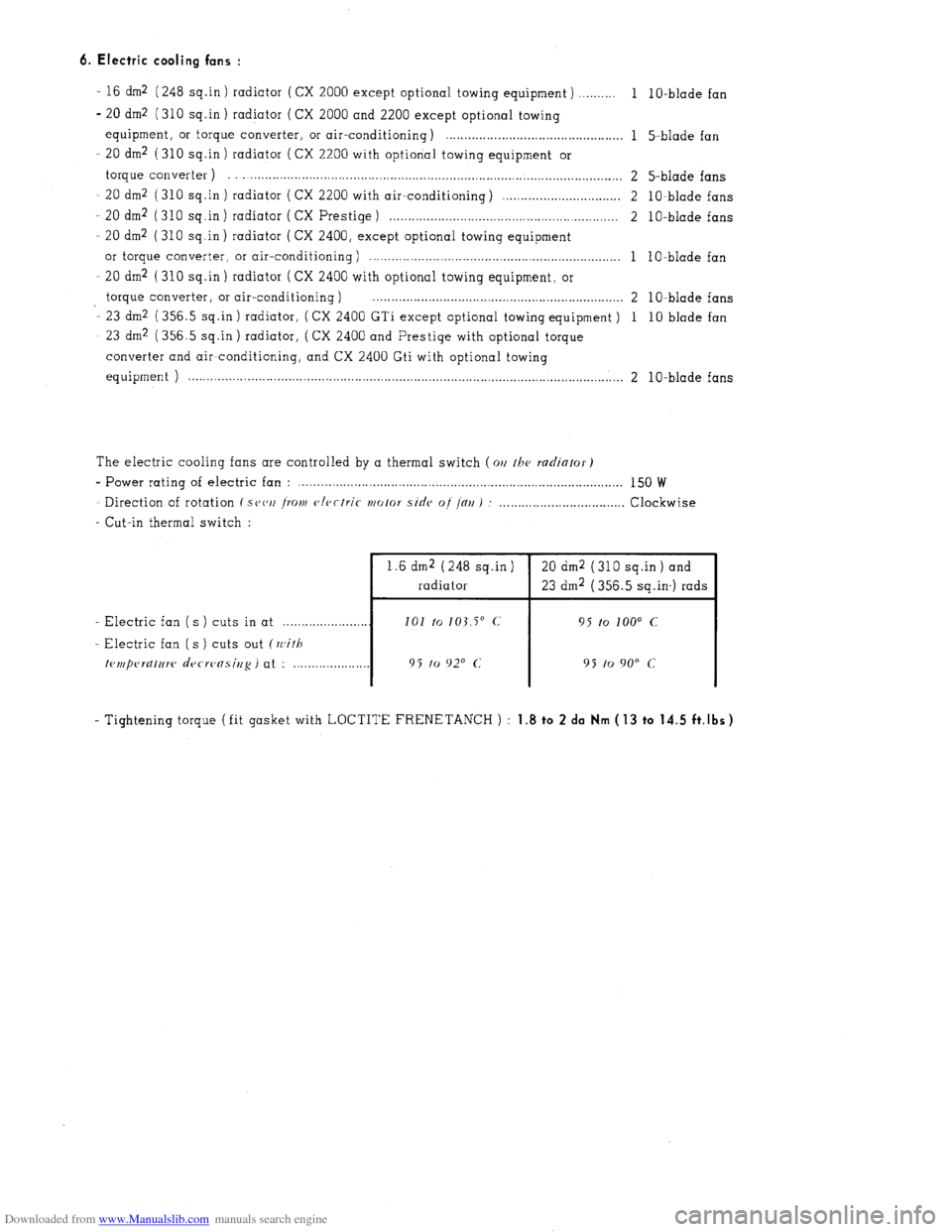
Downloaded from www.Manualslib.com manuals search engine 6. Electric cooling fans :
- 16 dm2 (248 sq.in ) radiator ( CX 2000 except optional towing equipment ) ,......... 1
- 20 dm2 (310 sq.in ) radiator (CX 2000 and 2200 except optional towing
equipment, or torque converter, or air-conditioning) . . . . . . . . . . . . . . . . . . . . . . . . . . . . . . . . . . . . . . . . . . . . . . . . 1
- 20 dm2 (310 sq.in ) radiator ( CX 2200 with optional towing equipment or
torque converter ) . . . . . . . . . . . . . . . . . . . . . . . . . . . . . . . . . . . . . . . . . . . . . . . . . . . . . . . . . . . . . . . . . . . . . . . . . . . . . . . . . . . . . . . . . . . . . . . . . . . . . 2
20 dm2 (310 sq.in ) radiator ( CX 2200 with air-conditioning) ,............................... 2
- 20 dm2 (310 sq.in) radiator ( CX Prestige) . . . . . . . . . . . . . . . . . . . . . . . . . . . . . . . . . . . . . . . . . . . . . . . . . . . . . . . . . . . . . . 2
- 20 dm2 (310 sq.in) radiator (CX 2400, except optional towing equipment
or torque converter, or air-conditioning ) . . . . . . . . . . . . . . . . . . . . . . . . . . . . . . . . . . . . . . . . . . . . . . . . . . . . . . . . . . . . . . . . . . . . 1
20 dm2 ( 310 sq .in ) radiator ( CX 2400 with optional towing equipment, or
torque converter, or air-conditioning ) . . . . . . . . . . . . . . . . . . . . . . . . . . . . . . . . . . . . . . . . . . . . . . . . . . . . . . . . . . . . . . . . . . . . 2
- 23 dm2 (356.5 sq.in ) radiator, ( CX 2400 GTi except optional towing equipment ) 1
- 23 dm2 (356.5 sq.in) radiator, (CX 2400 and Prestige with optional torque
converter and air~conditioning, and CX 2400 Gti with optional towing
equipment ) . . . . . . . . . . . . . . . . . . . . . . . . . . . . . . . . . . . . . . . . . . . . . . . . . . . . . . . . . . . . . . . . . . . . . . . . . . . . . . . . . . . . . . . . . . . . . . . . . . . . . . . . . . . . . . . . . . . . . . 2 1 O-blade fan
5-blade fan
5-blade fans
lo-blade fans
1 O-blade fans
1 O-blade fan
1 O-blade fans
10 blade fan
lo-blade fans
The electric cooling fans are controlled by a thermal switch (011 /he
radiator)
e Power rating of electric fan : . . . . . . . . . . . . . . . . . . . . . . . . . . . . . . . . . . . . . . . . . . . . . . . . . . . . . . . . . . . . . . . . . . . . . . . . . . . . . . . . . . . . . . . . 150 W
Direction of rotation ( S(J(‘IJ ~YOIII
c>lcctric ~/o/or side of /alI ) : . . . . . Clockwise
- Cut-in thermal switch :
1.6 dm2 (248 sq.in ) 20 dm2 ( 310 sq.in ) and
radiator 23 dm2 (356.5 sq.in,) rads
- Electric fan ( s ) cuts in at . . 101 to
103.5” c, 95 to loo0 c
-. Electric fan ( s ) cuts out (with
trmperatnw decreasing )
at : ._._._._._........... 9 5 to 920 c 95 to 9o” c
- Tightening torque (fit gasket with LOCTITE FRENETANCH ) : 1.8 to 2 da Nm ( 13 to 14.5 ft.lbs)
Page 184 of 394
Downloaded from www.Manualslib.com manuals search engine OPERA1
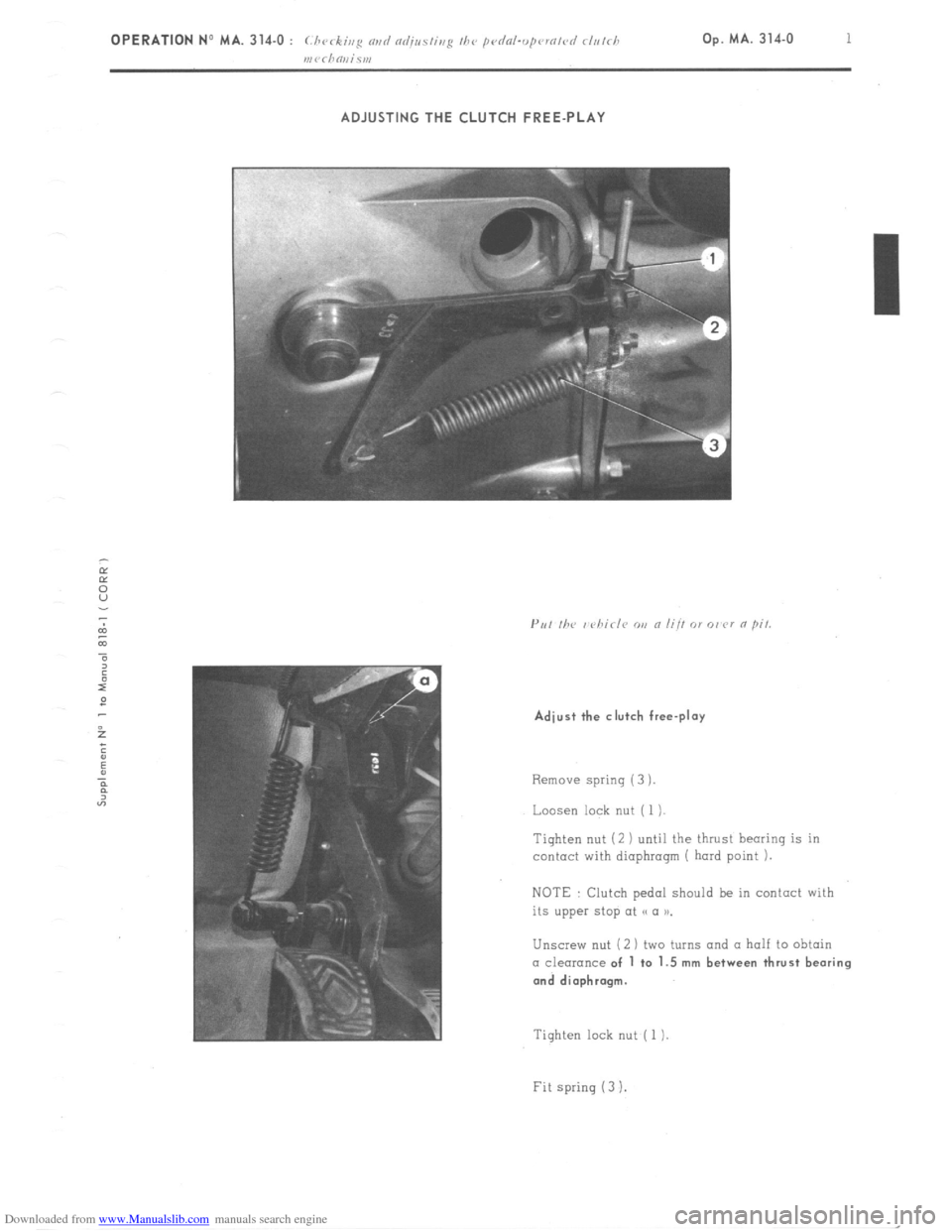
ADJUSTING THE CLUTCH FREE-PLAY
Adjust the clutch free-play
Remove spring (3 ).
Loosen lock nut ( 1 ).
Tighten nut (2 ) until the thrust hearing is in
contact with diaphragm ( hard point 1.
NOTE : Clutch pedal should be in contact with
its upper stop at << (I n.
Unscrew nut (2 1 two turns and a half to obtain CI clearance of 1 to 1.5 mm between thrust bearing
and diaphragm.
Tighten lock nut ( 1 )
Fit spring (3 I.
Page 189 of 394
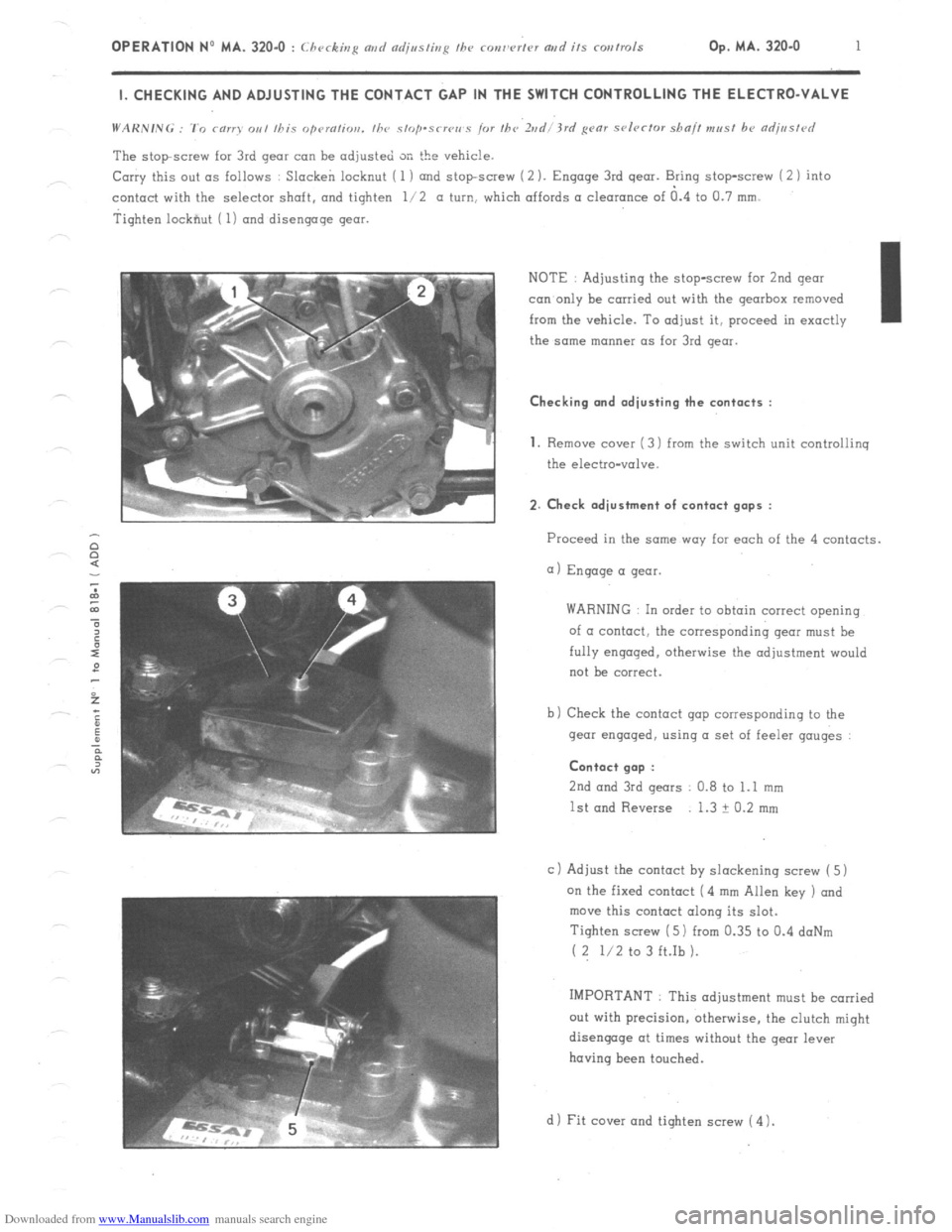
Downloaded from www.Manualslib.com manuals search engine OPERATION No MA. 320-O : Checking md czdjssting fhe ronw’rtcv artd its corrtrols Op. MA. 320.0 1 I. CHECKING AND ADJUSTING THE CONTACT GAP IN THE SWITCH CONTROLLING THE ELECTRO-VALVE
The stopscrew for 3rd gear can be adjusted SK the vehicle.
Carry this out as follows : Slacken locknut ( 1 ) and stopscrew (2 ). Engage 3rd gear. Bring stop-screw i 2 1 into
contact with the selector shaft. and tighten l/2 a turn, which affords a clearance of a.4 to Cl.7 mm.
Tighten lockfiut ( 1) and disengage gear.
NOTE : Adjusting the stop-screw for 2nd gear
con only be carried out with the gearbox removed
from the vehicle. To adjust it, proceed in exactly I
the same manner as for 3rd gear. Checking and adjusting the contacts :
1.
Remove cover ( 3) from the switch unit controliinq
the electro-valve. 2. Check adjustment of contact gaps :
Proceed in the same way far each of the 4 contacts.
a) Engage a gear.
WARNING In order to obtain correct opening
of a contact, the corresponding gear must be
fully engaged. otherwise the adjustment would
not be correct.
b) Check the contact gap corresponding to the
gear engaged, using a set of feeler gauges : Contact gap :
2nd
and 3rd gears 0.8 to 1.1 mm
1st and Reverse 1.3 ? 0.2 mm
c 1 Adjust the contact by slackening screw ( 5)
on the fixed contact (4 mm Allen key ) and
move this contact along its slot.
Tighten screw ( 5) from 0.35 to 0.4 doNm
( 2 l/2 to 3 ft.Ib ).
IMPORTANT : This adjustment must be carried
out with precision, otherwise, the clutch might
disengage at times without the gear lever
having been touched.
d 1 Fit cover and tighten screw ( 4 1.
Page 191 of 394
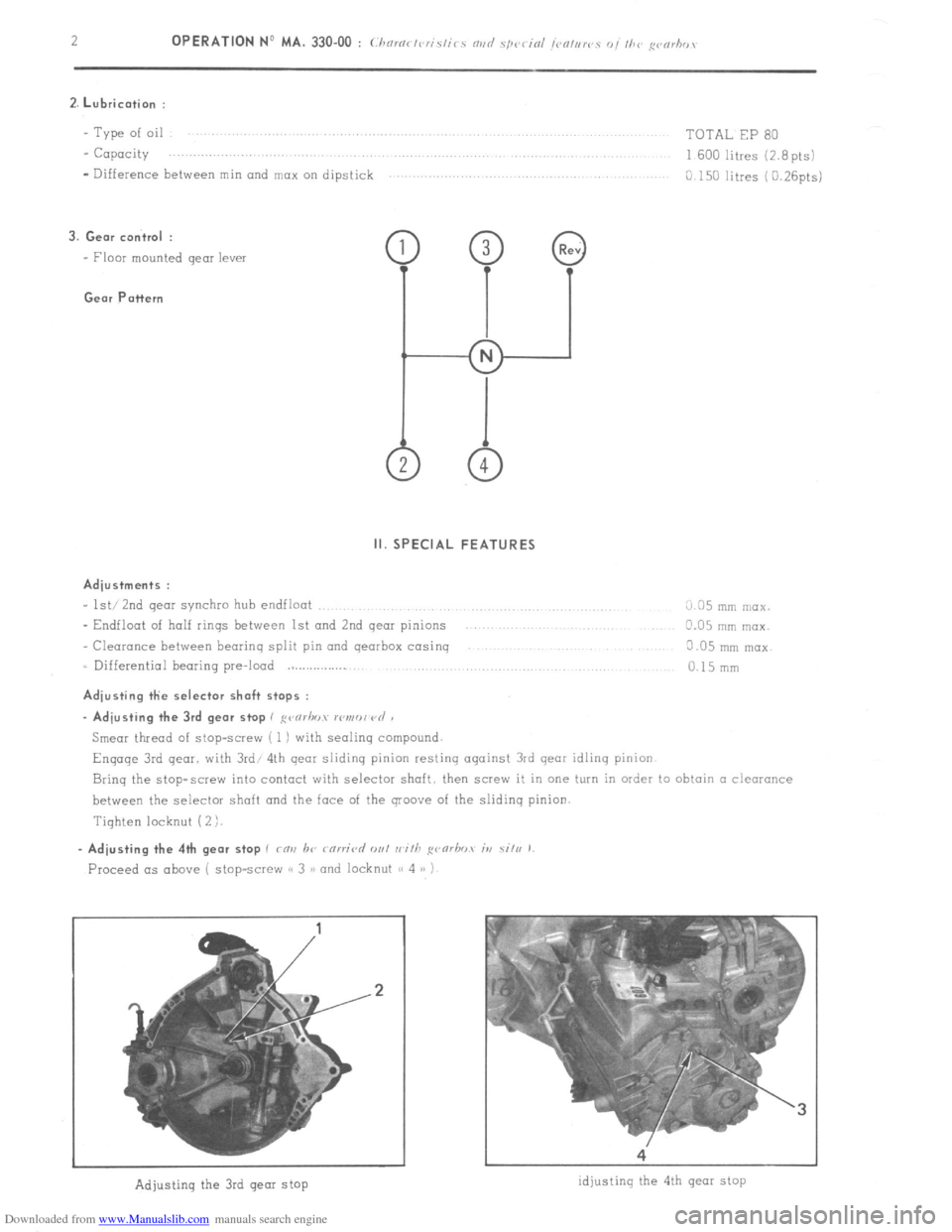
Downloaded from www.Manualslib.com manuals search engine 2. Lubrication :
- Type of oil
- Capacity
- Difference between min and mox on dipstick TOTAL EP 80
1600 litres (2.8pts)
C.150 litres (0.26pts)
3. Gem control :
- Floor mounted gear lever Gear Pattern
Il. SPECIAL FEATURES
Adjustments :
- lst/ 2nd gear synchro hub endfloot
_ Endfloot of half rinqs between 1st and 2nd qear pinions
- Clearance between beorinq split pin and qearbox cosinq
= Differential bearing pre-loud Adjusting the selector shaft stops : L/35 mln rnclx.
0.05 mm max.
3.05 mnl mox
c.15 mm
- Adjusting the 3rd gear stop I ,
Engage 3rd qear. with 3rd/ 4th qear slidinq pinion restinq aqainst 3rd qear idlinq pinion
Brinq the stop-screw into contact with selector shaft then screw it in one turn in order to obtain CI clearonce
between the selector shaft and the face of the groove of the slidinq pinion.
Tiqhten locknut ( 2 ).
Proceed as above ( stop-screw a< 3 > and locknut ,< 4 /> )
.2
Adjusting the 3rd gear stop idjustinq the 4th gear stop