lock Citroen CX 1981 1.G Owner's Guide
[x] Cancel search | Manufacturer: CITROEN, Model Year: 1981, Model line: CX, Model: Citroen CX 1981 1.GPages: 394
Page 263 of 394
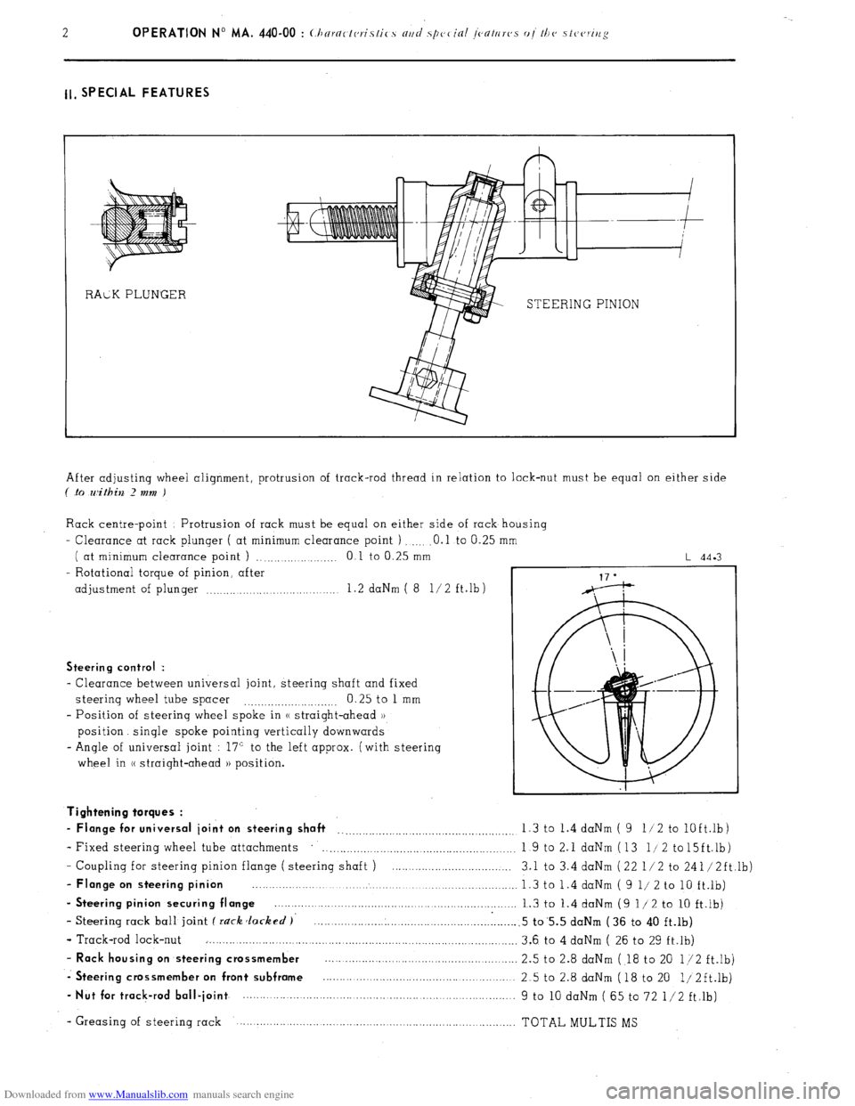
Downloaded from www.Manualslib.com manuals search engine ll, SPECIAL FEATURES
STEERING PINION
After adjusting wheel alignment, protrusion of track-rod thread in relation to lock-nut must be equal on either side
( .to within 2 mm )
Rack centre-point Protrusion of rack must be equal on either side of rack housing
- Clearance at rack plunger ( at minimum clearance point ) .O.l to 0.25
( at minimum clearance point ) ., .,...._...... .._._ 0 1 to 0.25 mm
- Rotational torque of pinion, after
adjustment of plunger .._..... .._.... 1.2 daNm ( 8 l/2 ft.lb)
L 44.3
Steering control :
- Clearance between universal joint, steering shaft and fixed
steering wheel tube spacer 0.25 to 1 mm
.._....__._..._.... ._..__..
- Position of steering wheel spoke in (( straight-ahead ))
position. single spoke pointing vertically downwards
- Angle of universal joint : 17” to the left approx. (with steering
wheel in (( straight-ahead )) position.
- Coupling for steering pinion flange ( steering shaft ) ....................................
- Flange on steering pinion ................................................................................
- Steering pinion securing flange ........................................................................
- Steering rack ball joint f rack Jacked )’ .............................................................
- Track-rod lock-nut ..............................................................................................
- Rack housing on steering crossmember ..........................................................
-. Steering crossmember on front subframe ..........................................................
- Nut for track-rod ball-joint ................. ................................... ..... ...................... Tightening torques :
- Flange for universal joint on steering shaft __..._.__.._._.........,.........................,. 1.3 to 1.4 daNm ( 9 11 2 to
lOft.lb)
- Fixed steering wheel tube attachments
. . . . . . . . . . . . . . . . . . . . . 1 9 to 2.1 daNm (13 l/2 to15ft.lb)
3.1 to 3.4 daNm (22 l/2 to 241/2ft,lb)
1.3 to 1.4 daNm ( 9 l/ 2 to 10 ft.lb)
1.3 to 1.4 daNm (9 l/2 to 10 ft.lb)
.5 to’5.5 daNm (36 to 40 ft.lb)
3.6 to 4 daNm ( 26 to 29 ft.lb)
2.5 to 2.8 daNm ( 18 to 20 l/2 ft.lb)
2.5 to 2.8 daNm (18 to 20 1/2ft.lb)
9 to 10 daNm ( 65 to 72 l/2 ft.lb)
- Greasing of steering rack TOTAL MULTIS MS
Page 264 of 394
Downloaded from www.Manualslib.com manuals search engine II. POWER STEERING WITH POWERED RETURN
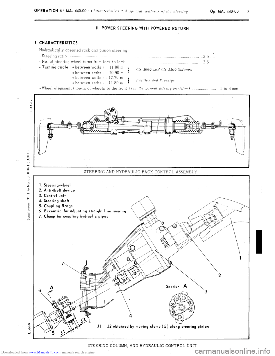
I. CHARACTERISTICS
Hydraulically operated rack and pinion steering Steering
ratio . . . . . . . . . . . . . . . . . . . . . . . . . . . . . . . . . . . . . . . . . . . . . . . . . . . . . . . . . . . . . . . . . . . . . . . . . . . . . . . . . . . . . . . . . . . . . . . . . . . . . . . . . . . . . . . . . . . . . . . . .. 13 5 i
- No of steering wheel turns from lock to lock
. . . . . . . .._._.__................................................ 25
- Turning circle (( between walls ))
11 80m
(.S x00 OIlCi ( s .2x0 solooll.~
(( between kerbs )) 10 90 m t
/( between walls )) 12 70 m
I( between kerbs 1) 11 80 m t I’\/N/l’ N/id I’n~\lix”
- Wheel alignment ( toe-in of wheels to the front i (i/l //I( //r~rjj/rll c/r;/ ii/:: p, cilirJ/i 1 1 to 4 mm
STEERING AND HYDRAULIC RACK CONTROL ASSEMBLY
1. Steering-wheel
2. Anti-theft device
3. Control unit
4. Steering shoft
5. Coupling flonge
6. Eccentric for odjusting stroight line running
7. Clomp for coupling hydraulic pipes
Jl J2 obtoined by moving clomp (5) olo
STEERING COLUMN, AND HYDRAULIC CONTROL UNIT
Page 266 of 394
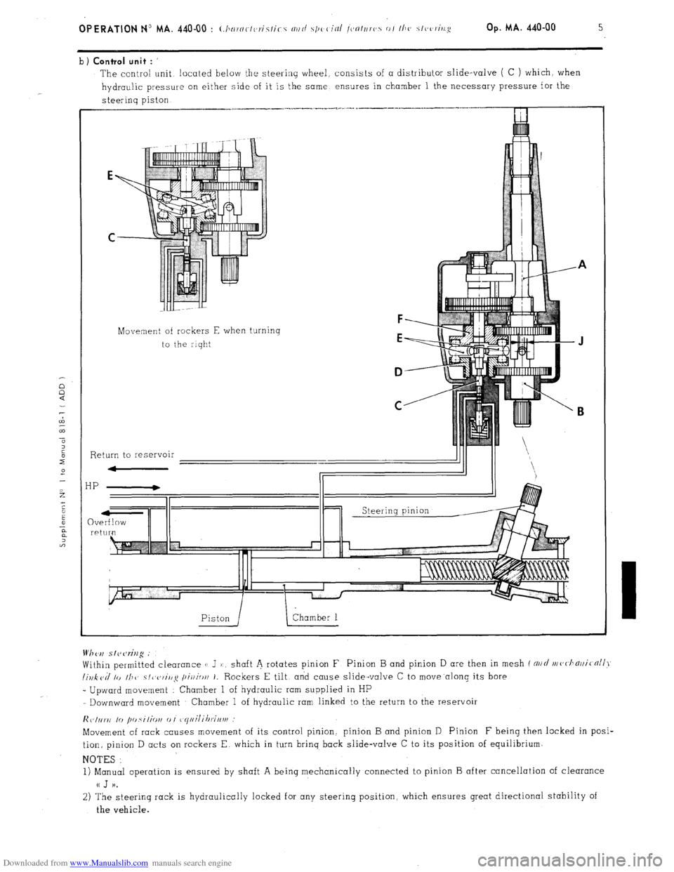
Downloaded from www.Manualslib.com manuals search engine b) Control unit : ’
The contra! unit located below the steering wheel, consists of a distributor slide-valve ( C ) which. when
hydraulic pressure on either side of it is the same ensures in chamber 1 the necessary pressure for the
steerinq piston
Movement of rockers E when turning
to the riqht
F
E
D
C
Return to reservoir
HP
QV re Wh <‘,I s I? cw%g .’
Within permitted clearance (1 J ):, shaft A rotates pinion F Pinion B and pinion D are then in mesh f NII~/ nl(,<.l1~)ji(nll>~
lillk cd lo II1 1’ ~/~~c,~i/lg /~ir/io/l 1. Rockers E tilt, and cause slide-valve C to move.along its bore
_ Upward movement : Chamber 1 of hydraulic ram supplied in HP
- Downward movement Chamber 1 of hydraulic ram linked to the return to the reservoir
lic,Inr~i lo fm.silio~i 0 I ~~yiiilihrif~vf
Movement of rack causes movement of its control pinion. pinion B and pinion D Pinion F being then locked in posi-
tion, pinion D acts on rockers E. which in turn brinq back slide-valve C to its position of equilibrium.
NOTES :
1) Manual operation is ensured by shaft A being mechanically connected to pinion B after cancellation of clearance
a J )).
2) The steering rack is hydraulically locked for any steering position, which ensures great directional stability of
the vehicle.
Page 272 of 394
Downloaded from www.Manualslib.com manuals search engine Op. MA. 440.00 11
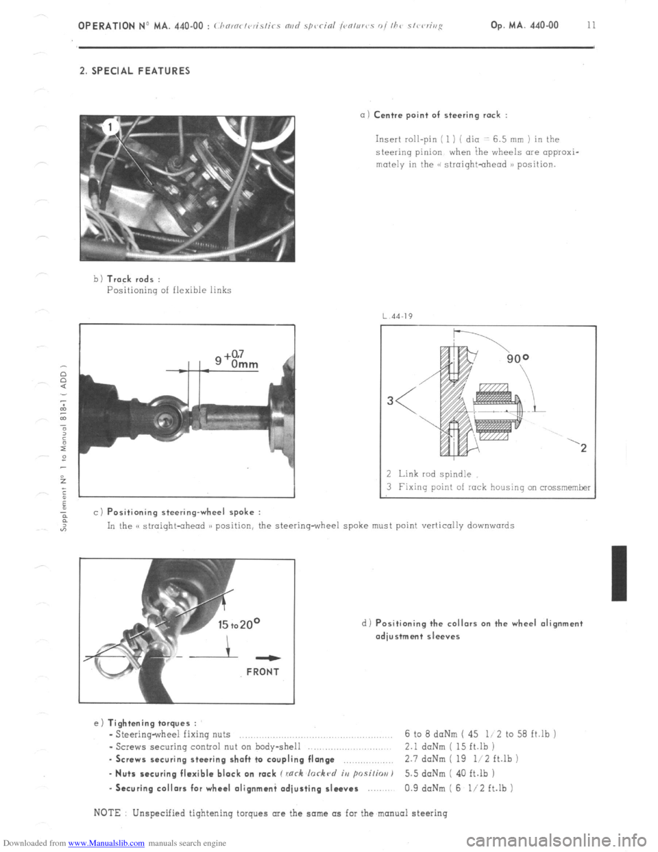
2. SPECIAL FEATURES
a) Centre point of steering rack :
Insert roll-pin ( 1 ) ( dio -: 6.5 mm ) in the
steering pinion when ihe wheels are appraxi-
mutely in the GG siroightohead )B position.
b 1 Track rods :
Positioning of flexible links
4J
a c) Positioning steering-wheel spoke :
2 Link rod spindle
3 Fixing point of rock housing on crossmemker
In the C( straight-ahead )) position, the steering-wheel spoke must point vertically
downwards
d) Positioning the collars on the wheel alignment
adjustment sleeves ---
FRONT
e) Tightening torques :
- Steering-wheel fixing nuts ..,.,........,......,.. .., 6 to 8 daNm ( 45 li 2 to 58 ft.lb j
- Screws securing control nut on body-shell 2.1 daNm ( 15 ft.lb )
. Screws securing steering shaft to coupling flange ,.,,.,,,,,.,.,.,,, 2.7 doNm ( 19 li2 ft.lb )
- Nuts securing flexible block on rack C rnrh lorkc~d iu psi/h) 5.5 doNm ( 40 ft.lb )
-Securing collars for wheel olignmani adjusting sleeves 0.9 daNm ( 6 l/2 ft.lb )
NOTE Unspecified tightening torques are the same as for the manual steering
Page 285 of 394
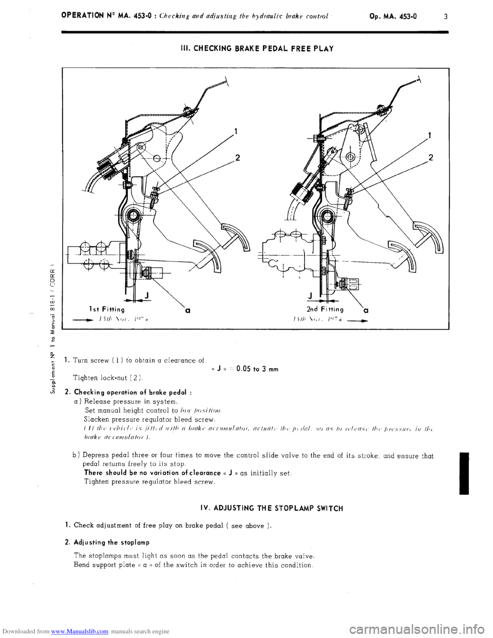
Downloaded from www.Manualslib.com manuals search engine OPERATION No MA. 453=0 : Ch J k’ ( c zng and adjjusfing thr hydraulk brake rontrol Op. MA. 453-O 3
III. CHECKING BRAKE PEDAL FREE PLAY
1 st Fitting 2nd Fitting
1 5 111 (I I /‘)7-t __t i%
+ 1. Turn screw ( 1 ) to obtain a clearance of
s
E
(( J )) ~~ 0.05 to 3 mm
-ii Tighten lock-nut ( 2 ).
2 2. Ch k’ ec Ing operation of brake pedal :
a) Release pressure in system.
Set manual height control to /or! /~~.s\‘itio~/
Slacken pressure regulator bleed screw.
( I/ Ill<, I <~/liClC~ is /ill1 rl i, ill, N I~tYlk~~ n~-rllrlll,Inlo,~. nc/un/1 II?<, /I< r/al.
hnke nr c111uu/n/0,. ).
b) Depress pedal three or four times to move the control slide valve to the end of its stroke, and ensure that
pedal returns freely to its stop.
There should be no variation of clearance o J )) as initially set.
Tighten pressure regulator bleed screw.
IV. ADJUSTING THE STOPLAMP SWITCH
1.
Check adjustment of free play on brake pedal ( see above ).
2. Adiusting the stoplamp
The stoplamps must light as soon as the pedal contacts the brake valve.
Bend support plate u a )) of the switch in order to achieve this condition.
Page 286 of 394
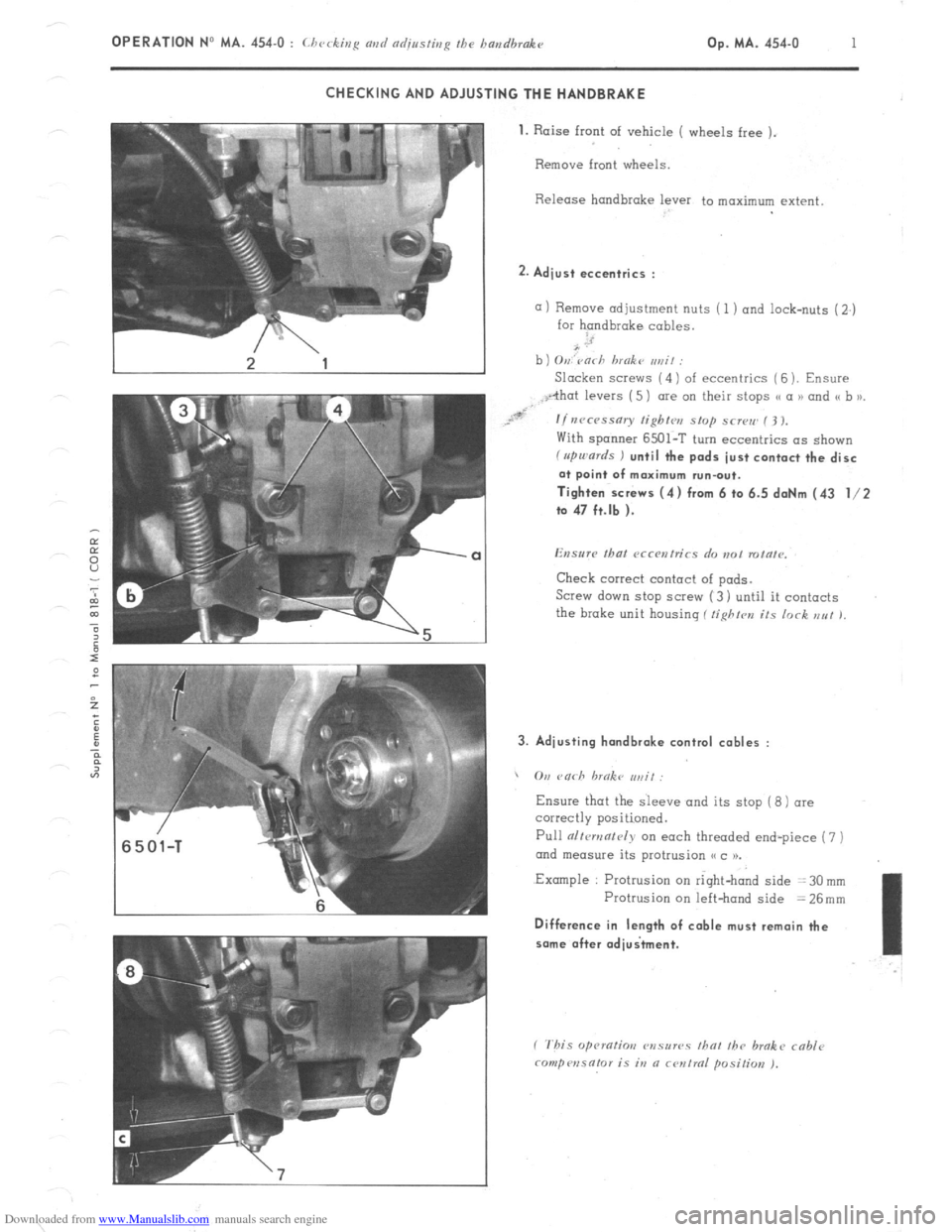
Downloaded from www.Manualslib.com manuals search engine OPERATION No MA. 454-O : Lhcckiu~ avd adjnsfbrR fhe bandbrake op. MA. 454-u I CHECKING AND ADJUSTING THE HANDBRAKE
1.
Raise front of vehicle ( wheels free ).
Remove front wheels.
Release handbrake lever to maximum extent 2. Adjust eccentrics :
a) Remove adjustment nuts ( 1 ) and lock-nuts (2.)
for handbrake cables.
b ) O,,,‘varh hmokt~ ,,rzit :
Slacken SCI~WS (4) of eccentrics ( 6 ). Ensure
With spanner 6501-T turn eccentrics as shown f rrpu,ards ) until the pads just contact the disc
at point of maximum run-out.
Tighten screws (4) from 6 to 6.5 daNm (43 l/2
to 47 ft.lb ).
Check correct contact of pads.
Screw down stop SCI~W (3) until it contacts
the brake unit housing ( tighfrn its lock EN! 1, 3. Adjusting hondbrake control cables :
, On rnrh hrnkc ,,,, if:
Ensure
Pull alfcmnf~~iy on each threaded end-piece (7 )
ond measure its protrusion (< c 1).
.Example : Protrusion on right-hand side = 30 mm
Protrusion on left-hand side = 26mm Difference in length of cable must remain the
some after adiuitment.
Page 287 of 394
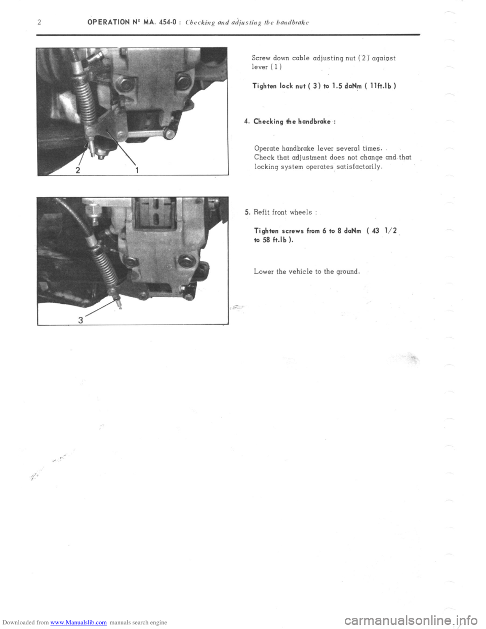
Downloaded from www.Manualslib.com manuals search engine OPERATION No MA. 454-O : Ch ec tzg and a&sting the handbrakc k’
Screw down cable adjusting nut (2) against
lever ( 1) Tighten lock nut ( 3) to 1.5 doNm ( llft.lb)
4. Checking tie handbrake :
Operate handbrake lever several times.
Check that adjustment does not change and that
locking system operates satisfactorily.
5. Refit front wheels : Tighten screws from 6 to 8 daNm ( 43 l/2,
ta 58 ft.lb ).
Lower the vehicle to the ground.
Page 289 of 394
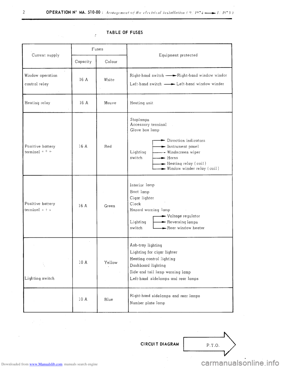
Downloaded from www.Manualslib.com manuals search engine TABLE OF FUSES
Current supply
findow operation
ontrol relay Fuses
Equipment protected
Capacity Colour
Right-hand switch -Right-hand window winder
16 A White
Left-hand switch - Left-hand window winder
Ieating relay 16 A Mauve Heating unit
Stoplamps
Accessory terminal
Glove box lamp
‘ositive battery
erminal (( + )). 16
A Red Direction indicators
E Instrument panel
Lighting -- Windscreen wiper
switch Horns
Heating relay ( coil )
Window winder relay ( coil )
‘ositive battery
erminal (( t 1) 16 A Green Interior lamp
Boot lamp
Cigar lighter
Clock
Hazard warning lamp
Lighting
switch
E
Voltage’ regulator
Reversing lamps
Rear window heater
Ash-tray lighting
10 A Yellow Lighting for cigar lighter
Heating control lighting
Dashboard lighting
,ighting switch Side- and tail lamp warning lamp
Left-hand sidelamps and rear lamps
10 A Blue Right-hand sidelamps and rear lamps
Number plate lamp Cl RCUI T DIAGRAM
r>
Page 292 of 394
Downloaded from www.Manualslib.com manuals search engine OPERATION No MA. 510-00 : \m//l‘!yc~tl/ <‘,/I 0 t Ih<’ <‘It,< Ir.itnl iusrtlllnliritt Op. MA. 510-00 3
f 0 lO7i-l,‘1975 )
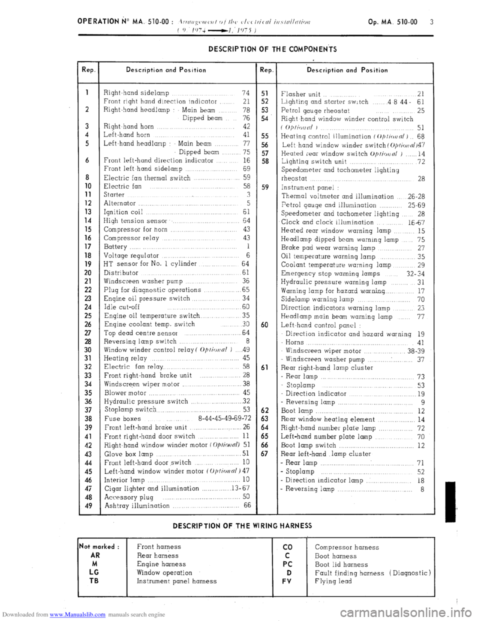
DESCRIPTION OF THE COMPONENTS
!ep. Description and Position Rep. ‘D escription and Position
1
Right hand sidelamp ...... 74 51
Flasher unit .. ....... 21
Front right hand direction indicator ..... 21 52 Lighting and starter switch .... .4 8’44- 61
2 Right-hand headlamp Main beam .. 78 5.3
76 54 Petrol gauge rheostat ........ 25
Dipped beam
Right hand window winder control switch
3 Right~hand horn ............ 42
( O/)liWlNl J ................. 51
4 Left-hand horn ...
41 55 Heating control illumination f ~///io~n/) .. 68
5 Left-hand headlamp : Main beam ....... 77 56
Left hand window winder switch ( O/JI~OII~/~~~
Dipped beam ...... 75 57
Heated rear window switch Op/io~nl j ...... 14
6 Front left-hand direction indicator ... 16 58
Lightinq switch unit ............. ........... 72
Front left hand sidelamp ................. 69
Speedometer and tachometer lighting
8 Electric fan thermal switch .................. 59
rheostat ....... ...... .................... 28 10
Electric fan .......
58 59 Instrument panel : 11
Starter ...... ... .............. .......... 3
Thermal voltmeter and illumination .. 26-28 12
Alternator ............................ ........ 5 13 Petrol gauge and illumination ............ 25-69
Ignition coil ... ......... .............. 61 14
Speedometer and tachometer lighting 28
High tension sensor ....................... 64
Clock and clock illumination ....... 1667 15
Compressor for horn ............ ..... ...... 43
Heated rear window warning lamp ....... 15 16
Compressor relay ................... ..... 43
Headlamp dipped beam warning lamp ... 75 17
Battery ............. .... .. 1
Brake pad wear warning lamp .......... 27 18
Voltage regulator ......................... 6
Oil temperature warning lamp ............ 35
19
HT sensor for No. 1 cylinder ........... 64
Coolant temperature warning lamp ....... 29 20
Distributor ..................... ...........
61 Emergency stop warning lamps 32” 34
21
Windscreen washer pump ............. 36
Hydraulic pressure warning lamp ...... 31 22
Plug for diagnostic operations ............. .65
Warning lamp for hazard warning.. ...... 17 23
Engine oil pressure switch .............. .. 34
Sidelamp warning lamp ................... 70 24
Idle cut-off ....................... .60
Direction indicators warning lamp ........... 23 25
Engine oil temperature switch ........... 35
Headlamp main beam warning lamp ... 77 26
Enqine coolant temp. switch ... 30 60 Left-hand control panel : 27
Top dead centre sensor ........................ 64 Direction indicator and hazard warning 19 28
Reversing lamp switch ........................ 8
- Horns .................................... 41 30
Window winder control relay( Optior~nl ) .. ..4 9
Windscreen wiper motor ............... 38-39 31
Heating relay ............ ..................... 45
- Windscreen washer pump .......... . .......... 37 32
Electric fan relay ................................ 58 61
Rear right-hand lamp cluster 33
Front right-hand brake unit ................. 28
- Rear lamp ............................................... 73 34
Windscre,en wiper motor ........................ 38
- Stoplamp ............. .....
............ 53
35
Blower motor ............ .............................. 45
Direction indicator ................................... 19 36
Hydraulic pressure switch ...................... . 32
- Reversing lamp ..................................... 9 37
Stoplamp switch.. ......................................... 53 62
Boot lamp ................................................. 12 38
Fuse boxes ..... 8-44-45-49-69-72 63 Rear window heating element ................... 14 39
Front left-hand brake unit .......................... 26 64
Right-hand number plate lamp ................. 72 41
Front right-hand door switch ................... 11 65
Left-hand number plate lamp ................... 70 42
Right-hand window winder motor f Optiollal) 51 66
Boot lamp switch ........................................ 12 43 Glove box
lamp ...................................... 51 67 Rear left-hand .lamp cluster 44
Front left-hand door switch ........ .......... 10 - Rear lamp ................................................ 71 45
Left-hand window winder motor (Oplio~fll) 47 s Stoplamp ........................................... 52 46
Interior lamp ................................................. 10
- Direction indicator lamp ..................... 18 47
Cigar lighter and illumination ............... .13-67
- Reversing lamp .................................... 8 48
Accessory plug ..... ... .......................... .... 50
49
Ashtray illumination ,., ... ................ 66 DESCRIPTION OF THE WIRING HARNESS
lot marked :
Front harness co Compressor harness AR
Rear harness C Boot harness
M Engine harness PC
Boot lid harness LG
Window operation D Fault finding harness ( Diagnostic) TB
Instrument panel harness FV Flying lead
Page 293 of 394
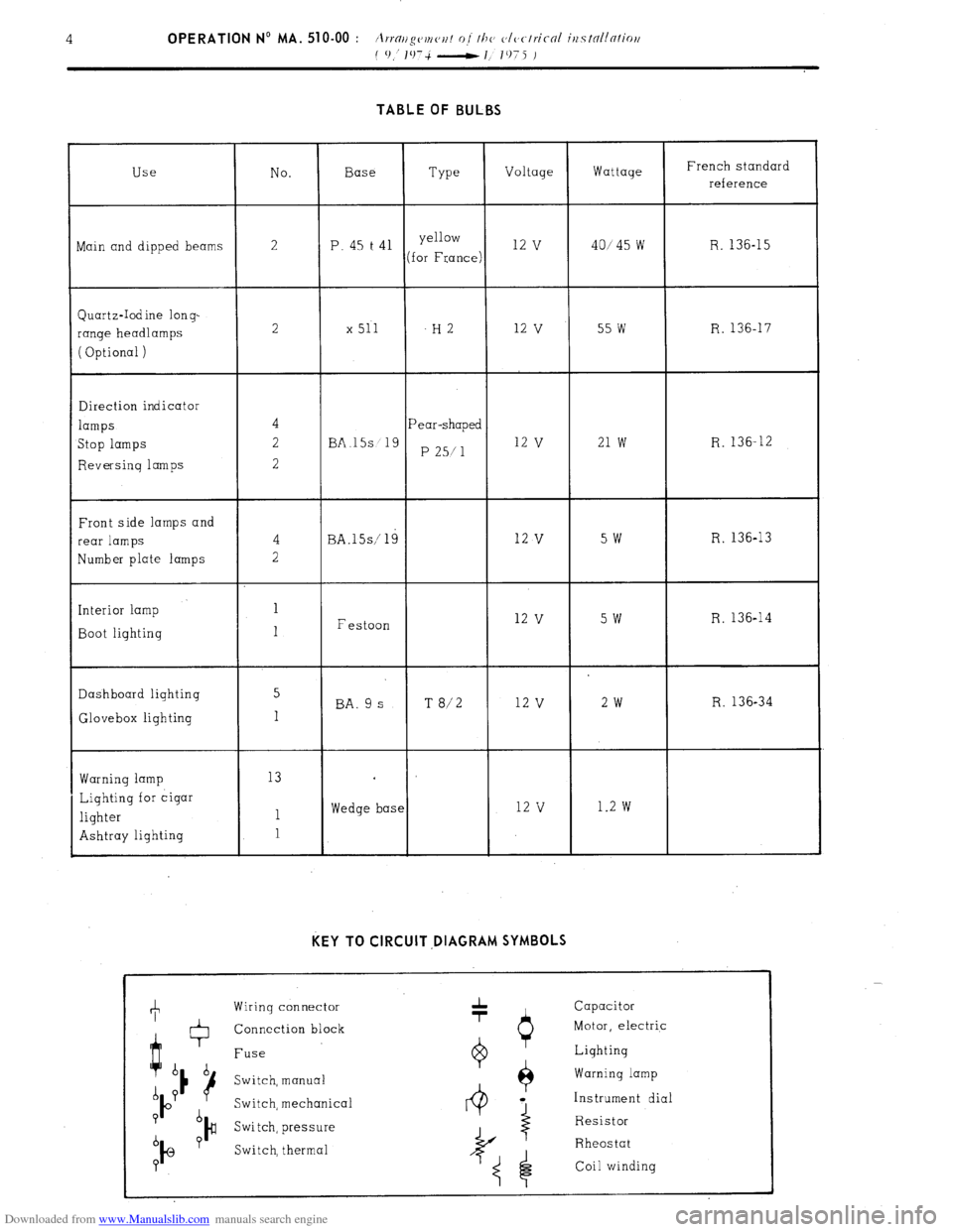
Downloaded from www.Manualslib.com manuals search engine TABLE OF BULBS
Use No. Base
Type Voltage Wattage French standard
reference
ain and dipped beams 2 P. 45 t 41 yellow 12 v 40145 w R. 136-15
(for France)
Quartz-Iodine long-
range headlamps
( Optional ) 2 x 511 -H2 12
v 55 w R. 136-17
Direction indicator
lamps
Stop lamps
Reversing lamps Pear-shaped
BA.15s 19
P 25/l 12 v 21 w R. 136-12
Front side lamps and
rear lamps
Number plate lamps
Interior lamp
Boot lighting BA.lSs/ 19
Festoon 12 v 5w R. 136-13 12
v 5w R. 136-14
Dashboard lighting 5
BA. 9 s T 8/2 12 v 2w R. 136-34
Glovebox lighting 1
Warning lamp
Lighting for cigar
lighter
Ashtray lighting 13
1
1 Wedge base 12 v 1.2 w KEY TO CIRCUIT ,DIAGRAM SYMBOLS
Wiring connector
Connection block
Fuse
Switch, manual
Switch, mechanica
Switch, pressure
Switch, thermal 1 Capacitor
Motor, electric
0 Lighting
$ Warning lamp
4 a Instrument dial
Resistor
I
Rheostat
Coil winding