lock Citroen CX 1981 1.G Repair Manual
[x] Cancel search | Manufacturer: CITROEN, Model Year: 1981, Model line: CX, Model: Citroen CX 1981 1.GPages: 394
Page 375 of 394
Downloaded from www.Manualslib.com manuals search engine 6
OPERATION No MA. 640-O : ( hvrsi~/p nsd ndj/w/isyc /I><, nirr~,s~l;/io,,i,,,~ syc,<,,,,
B. VEHICLES FITTED WITH A SANI(Y0 COMPRESSOR
NOTE Filling operations on CI vehicle fitted with a
and differ from the (< ASPERA-FRIGO 1) compressor only in as much as there are no screws for opening and closing
the valves.
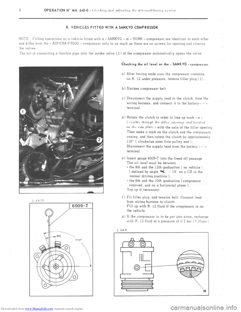
The act of connecting a flexible pipe onto the intake valve (2) of the compressor automatically opens the valve. Checking the oil level on the cc SANKYO ~ncompressor
(11 After having made’swe, the compressor contains
no R. 12 under pressure, remove filler plug ( 1).
b) Slacken compressor belt
cj Disconnect the supply lead to the clutch, from the
wiring harness. and connect it to the battery<, + >)
terminal.
d) Rotate the clutch in order to line up mark ,< a ))
( visihlc~ tllrou~h Ihv /i/ler
opvui,,p. nad lorn/~~d
w I/TV rnw flnle ) with the axis of the filler opening.
Then make a mark on the clutch and the compressor
co-sing. and then rotate the clutch by opproximotely
110’ ( clockwise seen from pulley end ).
Disccninect the supply lead from the battery <( + )a
terminal.
e) Insert gouge 6009-T into the freed off passage
The oil level must be between
- the 8th and the 12th graduation ( on vehicle )
( defined by angle aC = 19. on a CX in the
normal driving position ).
- the 6th and the 10th graduation (compressor
removed. and on a horizontal plane ).
Top up if necessary.
f 1 Fit filler plug, and tension belt. Connect iead
from wiring hcrness to clutch.
Fill up with R. 12 fluid if the compressor is on
the vehicle.
g) If the compressor is to be put into store. rechange
with R. 12 fluid at o pressure of 0.5 bar (7.25psi)
L 64.9
Page 384 of 394
Downloaded from www.Manualslib.com manuals search engine OPERATION No MA. 841-O : Adjusting fh~ doors Op. MA. 841-O 1 I. ADJUSTING A FRONT DOOR
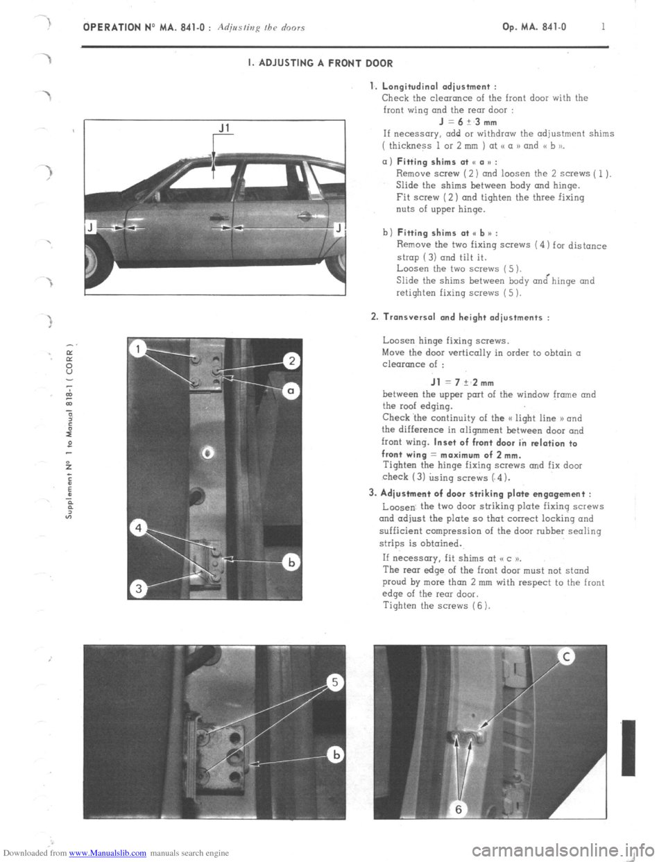
1. Longitudinal adiustment :
Check
the clearance of the front door with the
front wing and the rear door : J=6+_3mm
If necessary. add or withdraw the adjustment shims
( thickness 1 or 2 mm ) at <( a 1) and << b to_ a) Fitting shims at SC a u :
Remove screw (2) and loosen the 2 screws ( 1).
Slide the shims between hody and hinge.
Fit screw (2) and tighten the three fixing
nuts of upper hinge.
b) Fitting shims at <, b n :
Remove the two fixing screws (4) for distance
strop (3) and tilt it.
Loosen the two screws (5 ).
Slide the shims between body &hinge and
retighten fixing screws (5 ). 2. Transversal and height adjustments :
Loosen hinge fixing screws.
Move the door vertically in order to obtain a
clearance of : Jl = 7 +‘2mm
between the upper port of the window frame and
the roof edging.
Check ‘the continuity of the a light line 1) and
the difference in alignment between door and
front wing. Inset of front door in relation to
front wing = maximum of 2 mm.
Tighten the hinge fixing SCWNS and fix door
check (3) using screws (“4). 3. Adjustment of door striking plate engagement :
Loosen. the two door striking plate fixing screws
and adjust the plate so that correct locking and
sufficient compression of the door rubber sealing
strips is obtained.
If necessary, fit shims at (cc )P.
The rear edge of the front door must not stand
proud by more than 2 mm with respect to the front
edge of the rear door.
Tighten the screws (6 ).
Page 385 of 394
Downloaded from www.Manualslib.com manuals search engine 2 OPERATION NO MA. 841-O : Adjmfing /he o’r,ors
II. ADJUSTING A REAR DOOR
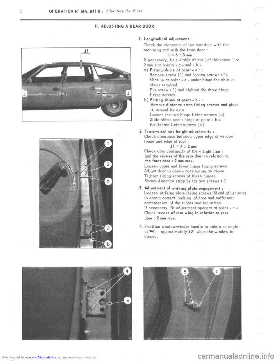
1. Longitudinal adjustment :
Check the clearonce of the rear door with the
rear wing and with the front door :
J =6+~3mm
If necessary, fit Suitable shims ( of thickness 1 or
2 mm ) at points (( a N and (( b )).
a) Fitting shims at point II a * :
Remove screw ( 1) ond loosen screws (2).
Slide in at point I< a D under hinge the shim or
shims required.
Fix scr&v (2 ).and tighten the three hinge
fixing screws.
b)
Fitting shims at point e b u :
Remove distance strop fixing screws and pivot
it, around its axis.
Loosen the two hinge fixing screws (4).
Slide shims under hinge at point <, b >j.
Re-tighten fixing screws (4 1.
2. Transversal and height adjustments :
Check clearance between upper edge of window
frmne and
edqe of roof :
Jl =7+~2mm
Check also continuity of the G light line x
and the recess
of the rear door in relation ta
the front door : 2 mm max.
Loosen upper and lower hinge fixing screws.
Adjust door to obtain positioning (IS above.
Tighten fixing screws of these hinges.
Secure distance strap by its two screws (3)
3. Adjustment of striking plate engagement :
Loosen striking plate fixing screws (3) and adjust so as
to obtain correct locking of door and sufficient
compression of the rubber sealing strips.
If necessary, fit adjustment spacers at point o c u.
Check recess
of rear wing in relation ta rear
dwr : 2 mm max.
4: Position window-winder handle to obtain an angle.
of W = approximately 30’ when the window is
closed.
Page 386 of 394
Downloaded from www.Manualslib.com manuals search engine OPERATION No MA. 844-O : Ad;,/<~lics /be hoot /ic/ Op. MA. 844-O 1
ADJUSTING THE BOOT LID
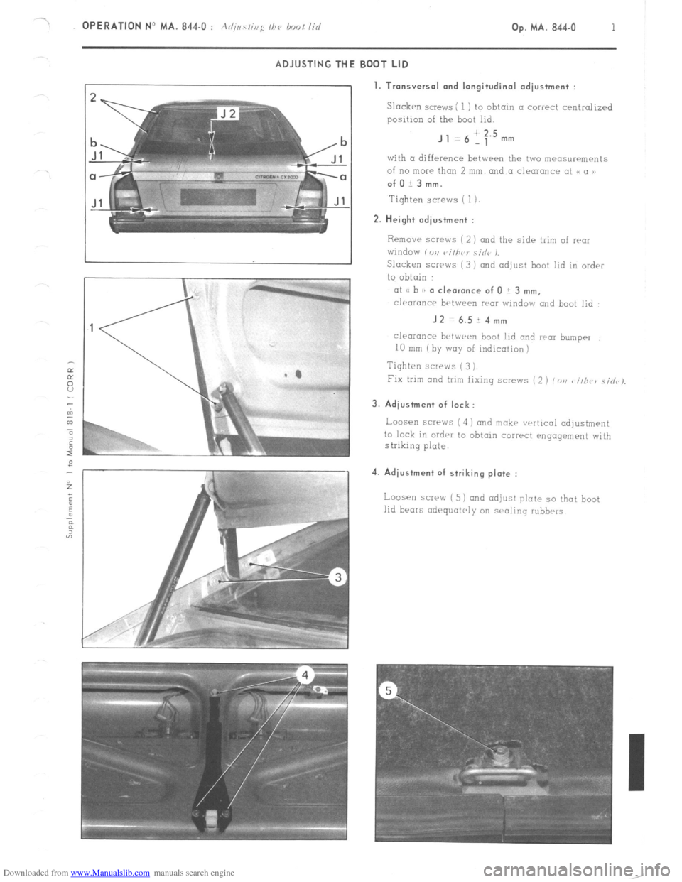
1. Tronsversol and longitudinal odiustment :
Slacken SCEWS ; 1 ) to obtain (I correct cenirolized
position of the boot lid.
J , 6 ! :‘” mm
with CL difference betwrrn the two meosurrments
of no more than 2 mm. and a clearance ot 18 a 1, ofOi3mm.
Tighten SCIWS ( 1). 2. Height odiustment :
Remove screws ( 2 ) and the sidr trim of rwr
window i vu vi/h~‘r ciriv ,.
Slacken screws ( 3 1 and adjust boot lid in order
to obtain
at I, b a/ a cle.r.nce of 0 ! 3 mm,
clraranc~ brtween war
window rmd boot lid : JZ-6.514mm
clearancr brtwrrn boot lid and rwr bumper
10 rmn (by way of indication)
Tighten screws ( 3 ).
Fix trim and trim fixing screws ( 2 ) /DU c iih~ ) \i&).
3. Adjustment of lock:
Loosen screws ( 4 i and mokr vertical odjustmrnt
to lock in ordrr to obtain correct engagement with
striking plate. 4. Adiustment of striking plate :
Loos-n screw ( 5) and adjust plate so that boot
lid bears odrquatrly on sealing rubbe‘s
Page 387 of 394
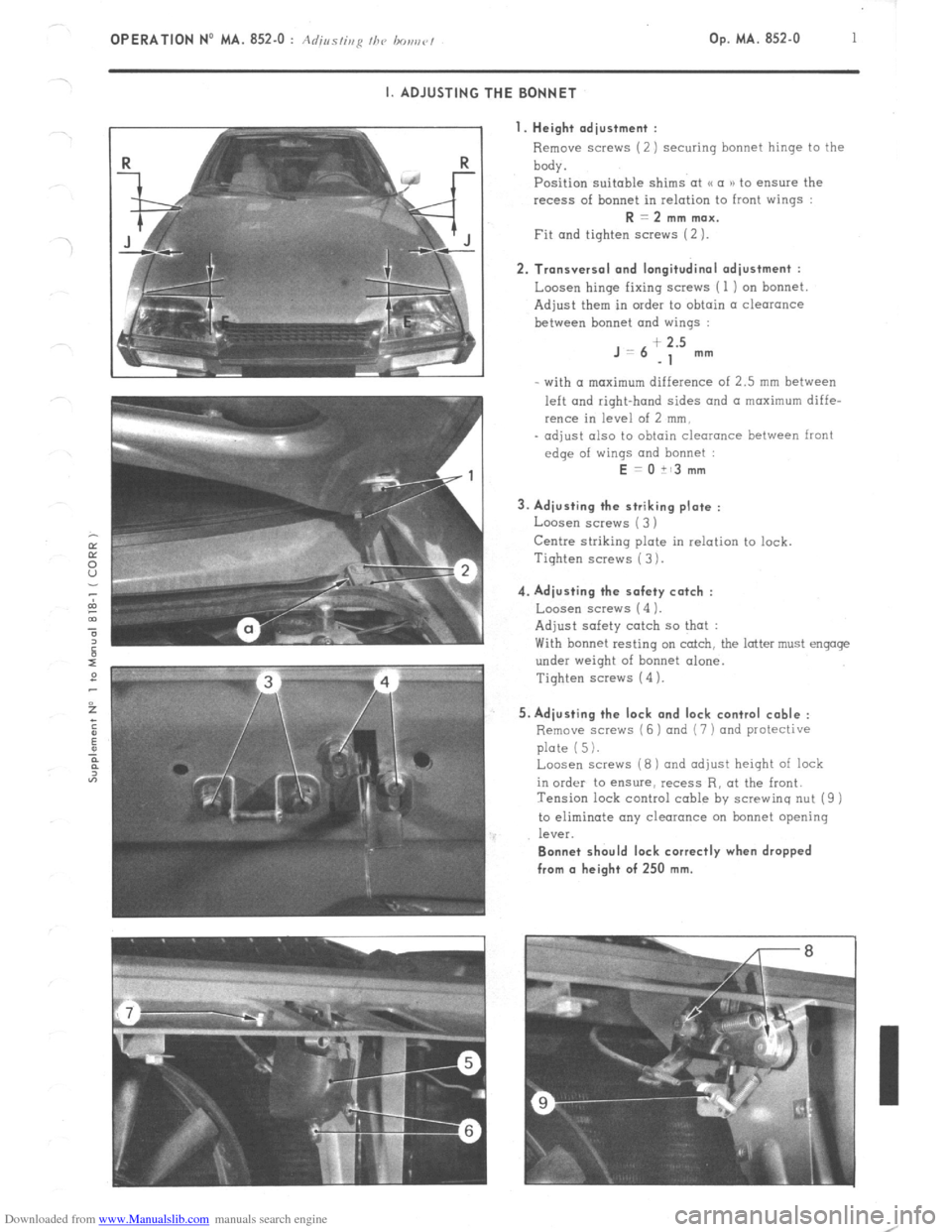
Downloaded from www.Manualslib.com manuals search engine OPERATION No MA. 852-O : Adius/ir,y I/><, bo,,r,r/ Op. MA. 852-O 1
~.
I. ADJUSTING THE BONNET
I. Height adjustment :
Remove screws (2) securing bonnet hinge to the
body.
Position suitable shims at u a )) to ensure the
recess of bonnet in relation to front wings : R = 2 mm max.
Fit and tighten screws (2 ). 2. Transversal and longitudinal adjustment :
Loosen hinge fixing screws ( 1 ) on bonnet
Adjust them in order to obtain a clearance
between bonnet and wings : J=6
+ 2.5
-1 mm
- with (I maximum difference of 2.5 mm between
left and right-hand sides and a maximum diffe-
rence in level of 2 mm,
- adjust also to obtain clearance between front
edge of wings and bonnet : E = 0 it3 mm
3. Adjusting the striking plate :
Loosen screws ( 3 )
Centre striking plate in relation to lock.
Tiqhten screws ( 3 ). 4. Adjusting the safety catch :
Loosen screw5 (4 1.
Adjust safety catch so that :
With bonnet resting on catch, the latter must engage
under weight of bonnet alone.
Tighten screws (4 ). 5. Adjusting the lock and lock control cable :
Remove scravs (6 ) and (7 ) and protective
plate (5).
Loosen screws (8) and adjust height of lock
in order to ensure, recess R, at the front.
Tension lock control cable by screwing nut (9 )
to eliminate any clearance on bonnet opening
leV%. Bonnet should lock correctly when dropped
from (I height of 250 mm.
Page 388 of 394
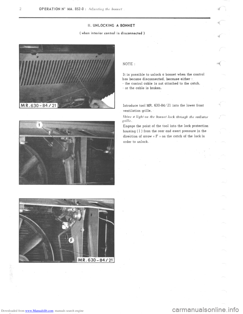
Downloaded from www.Manualslib.com manuals search engine 2
OPERATION No MA. 852.0 : Acfirrr~isg /hr, bos,rv/ I II. UNLOCKING A BONNET
(when interior control is disconnected )
‘I
NOTE :
-! It is possible to unlock (I bonnet when the control
has become discpnnected, because either :
- the control cable is not attached to the catch,
or the cable is broken.
Introduce tool MR. 630-84/21 into the lower front
ventilation grille.
Shine
a lighf on tbc bonnrl lock though the radia/or
grille.. Engage the point of the tbol into the lock protection
housing (1 ) from the rear and exert pressure in the
dire&on of arrow CC F n on the catch of the lock in
order to unlock