engine Citroen CX 1981 1.G Workshop Manual
[x] Cancel search | Manufacturer: CITROEN, Model Year: 1981, Model line: CX, Model: Citroen CX 1981 1.GPages: 394
Page 291 of 394

Downloaded from www.Manualslib.com manuals search engine
Page 292 of 394
Downloaded from www.Manualslib.com manuals search engine OPERATION No MA. 510-00 : \m//l‘!yc~tl/ <‘,/I 0 t Ih<’ <‘It,< Ir.itnl iusrtlllnliritt Op. MA. 510-00 3
f 0 lO7i-l,‘1975 )
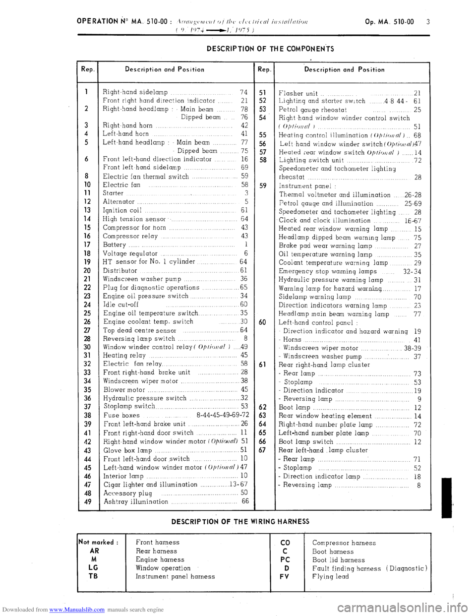
DESCRIPTION OF THE COMPONENTS
!ep. Description and Position Rep. ‘D escription and Position
1
Right hand sidelamp ...... 74 51
Flasher unit .. ....... 21
Front right hand direction indicator ..... 21 52 Lighting and starter switch .... .4 8’44- 61
2 Right-hand headlamp Main beam .. 78 5.3
76 54 Petrol gauge rheostat ........ 25
Dipped beam
Right hand window winder control switch
3 Right~hand horn ............ 42
( O/)liWlNl J ................. 51
4 Left-hand horn ...
41 55 Heating control illumination f ~///io~n/) .. 68
5 Left-hand headlamp : Main beam ....... 77 56
Left hand window winder switch ( O/JI~OII~/~~~
Dipped beam ...... 75 57
Heated rear window switch Op/io~nl j ...... 14
6 Front left-hand direction indicator ... 16 58
Lightinq switch unit ............. ........... 72
Front left hand sidelamp ................. 69
Speedometer and tachometer lighting
8 Electric fan thermal switch .................. 59
rheostat ....... ...... .................... 28 10
Electric fan .......
58 59 Instrument panel : 11
Starter ...... ... .............. .......... 3
Thermal voltmeter and illumination .. 26-28 12
Alternator ............................ ........ 5 13 Petrol gauge and illumination ............ 25-69
Ignition coil ... ......... .............. 61 14
Speedometer and tachometer lighting 28
High tension sensor ....................... 64
Clock and clock illumination ....... 1667 15
Compressor for horn ............ ..... ...... 43
Heated rear window warning lamp ....... 15 16
Compressor relay ................... ..... 43
Headlamp dipped beam warning lamp ... 75 17
Battery ............. .... .. 1
Brake pad wear warning lamp .......... 27 18
Voltage regulator ......................... 6
Oil temperature warning lamp ............ 35
19
HT sensor for No. 1 cylinder ........... 64
Coolant temperature warning lamp ....... 29 20
Distributor ..................... ...........
61 Emergency stop warning lamps 32” 34
21
Windscreen washer pump ............. 36
Hydraulic pressure warning lamp ...... 31 22
Plug for diagnostic operations ............. .65
Warning lamp for hazard warning.. ...... 17 23
Engine oil pressure switch .............. .. 34
Sidelamp warning lamp ................... 70 24
Idle cut-off ....................... .60
Direction indicators warning lamp ........... 23 25
Engine oil temperature switch ........... 35
Headlamp main beam warning lamp ... 77 26
Enqine coolant temp. switch ... 30 60 Left-hand control panel : 27
Top dead centre sensor ........................ 64 Direction indicator and hazard warning 19 28
Reversing lamp switch ........................ 8
- Horns .................................... 41 30
Window winder control relay( Optior~nl ) .. ..4 9
Windscreen wiper motor ............... 38-39 31
Heating relay ............ ..................... 45
- Windscreen washer pump .......... . .......... 37 32
Electric fan relay ................................ 58 61
Rear right-hand lamp cluster 33
Front right-hand brake unit ................. 28
- Rear lamp ............................................... 73 34
Windscre,en wiper motor ........................ 38
- Stoplamp ............. .....
............ 53
35
Blower motor ............ .............................. 45
Direction indicator ................................... 19 36
Hydraulic pressure switch ...................... . 32
- Reversing lamp ..................................... 9 37
Stoplamp switch.. ......................................... 53 62
Boot lamp ................................................. 12 38
Fuse boxes ..... 8-44-45-49-69-72 63 Rear window heating element ................... 14 39
Front left-hand brake unit .......................... 26 64
Right-hand number plate lamp ................. 72 41
Front right-hand door switch ................... 11 65
Left-hand number plate lamp ................... 70 42
Right-hand window winder motor f Optiollal) 51 66
Boot lamp switch ........................................ 12 43 Glove box
lamp ...................................... 51 67 Rear left-hand .lamp cluster 44
Front left-hand door switch ........ .......... 10 - Rear lamp ................................................ 71 45
Left-hand window winder motor (Oplio~fll) 47 s Stoplamp ........................................... 52 46
Interior lamp ................................................. 10
- Direction indicator lamp ..................... 18 47
Cigar lighter and illumination ............... .13-67
- Reversing lamp .................................... 8 48
Accessory plug ..... ... .......................... .... 50
49
Ashtray illumination ,., ... ................ 66 DESCRIPTION OF THE WIRING HARNESS
lot marked :
Front harness co Compressor harness AR
Rear harness C Boot harness
M Engine harness PC
Boot lid harness LG
Window operation D Fault finding harness ( Diagnostic) TB
Instrument panel harness FV Flying lead
Page 293 of 394
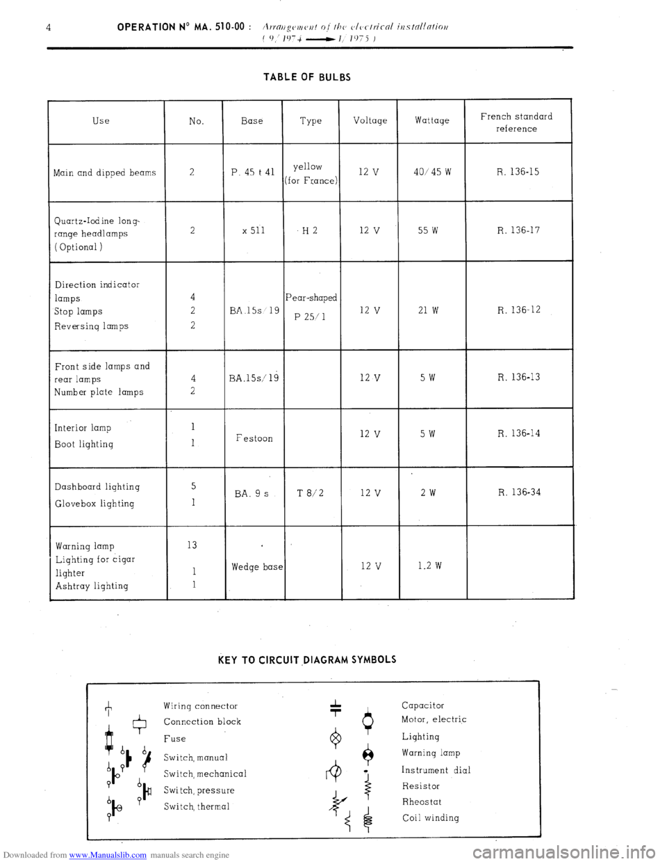
Downloaded from www.Manualslib.com manuals search engine TABLE OF BULBS
Use No. Base
Type Voltage Wattage French standard
reference
ain and dipped beams 2 P. 45 t 41 yellow 12 v 40145 w R. 136-15
(for France)
Quartz-Iodine long-
range headlamps
( Optional ) 2 x 511 -H2 12
v 55 w R. 136-17
Direction indicator
lamps
Stop lamps
Reversing lamps Pear-shaped
BA.15s 19
P 25/l 12 v 21 w R. 136-12
Front side lamps and
rear lamps
Number plate lamps
Interior lamp
Boot lighting BA.lSs/ 19
Festoon 12 v 5w R. 136-13 12
v 5w R. 136-14
Dashboard lighting 5
BA. 9 s T 8/2 12 v 2w R. 136-34
Glovebox lighting 1
Warning lamp
Lighting for cigar
lighter
Ashtray lighting 13
1
1 Wedge base 12 v 1.2 w KEY TO CIRCUIT ,DIAGRAM SYMBOLS
Wiring connector
Connection block
Fuse
Switch, manual
Switch, mechanica
Switch, pressure
Switch, thermal 1 Capacitor
Motor, electric
0 Lighting
$ Warning lamp
4 a Instrument dial
Resistor
I
Rheostat
Coil winding
Page 294 of 394

Downloaded from www.Manualslib.com manuals search engine
Page 295 of 394

Downloaded from www.Manualslib.com manuals search engine
Page 296 of 394
Downloaded from www.Manualslib.com manuals search engine , OPERATION No MA. 510-00 a : Arrallgc~rnc~r~t of lhe c,lc,rlric-al i~fslnllnlio~~ Op. MA. 510-00 a 1
( I 1975-
7 1075 ) ARRANGEMENT OF THE ELECTRICAL INSTALLATION
(
l/1075 - 7; 1975 I
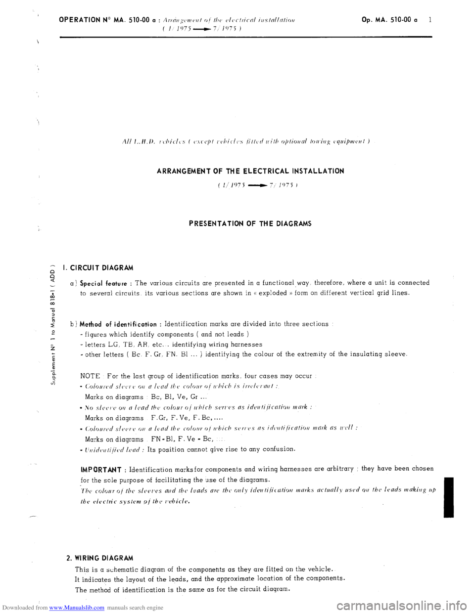
PRESENTATION OF THE DIAGRAMS
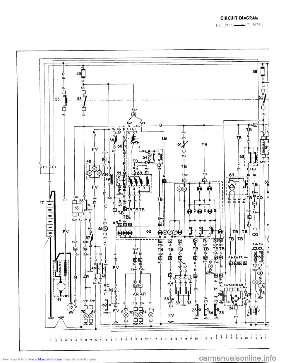
CIRCUIT DIAGRAM
a) Special feature : The various circuits are presented in a functional way. therefore, where a unit is connected
to several circuits, its various sections are shown in u exploded )) form on different vertical grid lines.
b) Method of identification
: Identification marks are divided into three sections
- figures which identify components ( and not leads )
-letters LG. TB. AR. etc. . identifying wiring harnesses
-other letters ( Bc. F. Gr. FN. Bl . . . ) identifying the colour of the extremity of the insulating sleeve.
NOTE For the last group of identification marks, four cases may occur
- (,‘0lortrc~d slcc’r,cJ 011 cl Ic,clrl 16~~ CVlVJlr clj ri,hic-I7 is irrc~lc~l~nrll :
Marks on diagrams Bc, Bl, Ve. Gr . . .
- No s1c~~j1.v 011 a Icad the colour oj rr,hich scrr’es as
idrrt tijicnfiotl mark :
Marks on diagrams F.Gr, F. Ve, F. Bc, . . . .
s
(.~~l~~llrC~~/ s[ppr,cj o,, o /cod the rolot~r oj ~r~bich SOF,~C’S ns idcvttijic-ntiotl mark as wc~ll :
Marks on diagrams FN - Bl, F. Ve - Bc,
I
l’rlidcrllijic~rl Icarl : Its position cannot give rise to any confusion. IMPORTANT
: Identification marksfor components and wiring harnesses are arbitrary : they have been chosen
for the sole purpose of facilitating the use of the diagrams. 2. WIRING DIAGRAM
This is a schematic diagram of the components as they are fitted on the vehicle.
It indicates the layout of the leads, and the approximate location of the components.
The method of identification is the same as for the circuit diagram.
Page 297 of 394
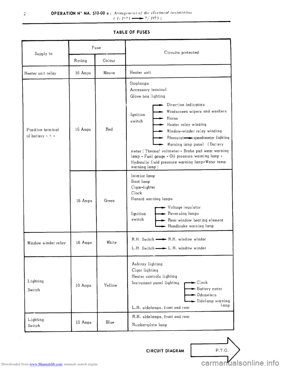
Downloaded from www.Manualslib.com manuals search engine TABLE OF FUSES
Supply to
eater unit relay Fuse
Circuits protected
Rating Colour
16 Amps Mauve Heater unit
S toplamps
Accessory terminal
Glove box lightinq
Positive terminal
of battery u + )) 16 Amps Red
E Direction indicators
Ignition Windscreen wipers and washers
switch Horns
Heater relay windinq
Window-winder relay winding
Rheostat -speedometer lighting
Warning lamp panel ( Battery
meter ( Thermal voltmeter-- Brake pad wear warning
lamp - Fuel gauge - Oil pressure warning lamp -
Hydraulic fluid pressure warning lamp-Water temp.
warning lamp )
16 Amps Green Interior lamp
Boot lamp
Cigar-lighter
Clock
Hazard warning lamps
E Voltage regulator
Iqnition Reversing lamps
switch
Rear window heating element
Handbrake warning lamp
Window winder relay 16 Amps White R.H. Switch 0 R.H. window winder
L.H. Switch- L.H. window winder
Lighting
Switch 10 Amps Yellow Ashtray lighting
Cigar lighting
Heater controls lighting
Instrument panel lighting Clock
E Battery meter
Odometers
Sidelamp warning
L.H. sidelamps, front and rear 1 amp
Lighting
Switch 10 Amps Blue R.H. sidelamps, front and rear
Number-plate lamp CIRCUIT DIAGRAM
>
P.T.O.
Page 298 of 394
Downloaded from www.Manualslib.com manuals search engine
Page 299 of 394

Downloaded from www.Manualslib.com manuals search engine
Page 300 of 394
Downloaded from www.Manualslib.com manuals search engine OPERATION N” MA. 510-00 a : Arrnr~g(,v~ ('I, I 0 / Ih CJ c~lvclric-cil irtslnllc7liori Op. MA. 510-00 a 3
(I.‘1975 -7 1975 J
-
den{
lark
i
6
8
9
0
1
2
3
4
5
6
7
8
9
!l
!2
!3
!4
!5
!6
!7
!8
$0
)l
12
33
34
35
36
37
38
39
41
42
43
44
45
46
47
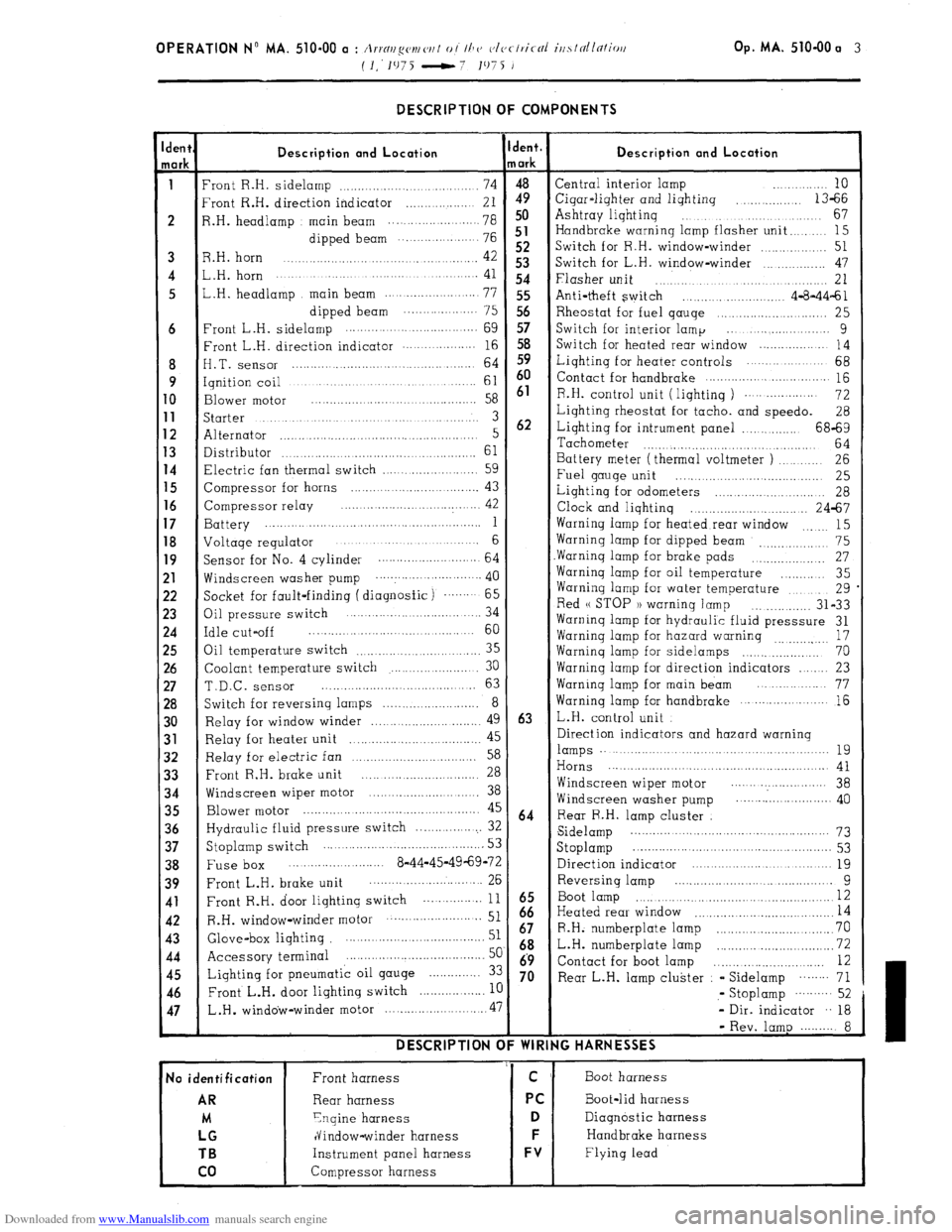
- DESCRIPTION OF COMPONENTS
Description and Location
‘ront R.H. sidelamp ................................... 74
‘rant R.H. direction indicator .................. 21
1.H. headlamp main beam ................. ..... 78
dipped beam ... .................. 76
3.H. horn 42 .............................................
,.H. horn ....................... ............. ............. 41
,.H. headlamp main beam .......................
77
dipped beam .................... 75
‘rant L.H. sidelamp .........
........................
69
:ront L.H. direction indicator .................. 16
I.T. sensor ............................................ 64
qnition coil ..............................................
61
3lower
motor .........................................
58
;tarter ...................................................... 3
Alternator ..................................................... 5
Xstributor 61 ...................................................
7lectric fan thermal switch .........................
59
Zompressor for horns ................................. 43
Compressor relay ..... .................
.............. 42
3attery ........... ...............................................
1
Joltaqe regulator ....................... ............. 6
jacket for fault-finding ( diagnosfic) ....... 65
3il pressure switch .... ....................... ... 34
:dle cut-off ........................................... 60
3il temperature switch
35 .............................
Coolant temperature switch ....................... 30
T.D.C. sensor ......................................... 63
Switch for reversing lamps .......................... 8
Relay for window winder ............................. 49
Relay for heater unit 45
................... ..............
Relay for electric fan 58 ..................................
Front R.H. brake unit 28 ...............................
Windscreen wiper motor .............................. 38
Blower motor ................................................ 45
Hydraulic fluid pressure switch ................... 32
Stoplamp switch ........................................... 53
Fuse box ..... .................... 8-44-45-49-69-72
Front L.H. brake unit ........................... ... 26
Front R.H. door lighting switch ... ............
11
R.H. window-winder motor .......................... 51
Glove-box lighting ....................................... 51
Accessory terminal ......................................
5c
Lighting for pneumatic oil gauge .............. 3:
Front L.H. door lighting switch
.................. I[ L.H .
window-winder motor ........................... .47 DESCRIPTION C
No identification
AR
M
LG
TB
co
Front harness
Rear harness
Ynqine harness
dindow-winder harness
Instrument panel harness
Compressor harness jent.
/ark
4”9 50
51
52
53
54
55
56
57
58
59
60
61
62
63
64
iz
67
68
69
70 Description and Location Central interior lamp ............ 10
Cigar-liqhter and lighting
.............. 13-66
Ashtray liqhtinq ...................................
67
Handbrake warning lamp flasher unit
........ 15
Switch for R.H. window-winder
.............. 51
Switch for L.H. window-winder ................ 47
Flasher unit .............................................. 21
Anti-theft switch ......................... 4-8-44-61
Rheostat for fuel qauqe ............................ 25
Switch for interior lamp ... ....................
9
Switch for heated rear window ...................
14
Liqhting for heater controls ..................... 68
Contact for handbrake
............................... 115
R.H. control unit ( liqhtinq )
................... 72
Lighting rheostat for tacho. and speedo.
28
Lighting for intrument panel ................ 68-69
Tachometer
............................................ 64
Battery meter (thermal voltmeter )
.......... 26
Fuel gauge unit
..... ....... ....... ................ 25
Lighting for odometers
....... ......... .......... 28
Clock and lighting ................................ 24-67
Warning lamp for heated rear window
15 .......
Warning lamp for dipped beam 75
_, .................
Warninq lamp for brake pads ................... 27
Warninq lamp for oil temperature
............ 35
Warning lamp for water temperature
.......... 29
Red u STOP 1) warninq lamp
............... 31-33
Warninq lamp for hydraulic fluid presssure 31
Warninq lamp for hazard warning
17
...............
Warninq lamp for sidelamps .................... 70
Warning lamp for direction indicators ...... 23
Warninq lamp for main beam ................. 77
Warning lamp for handbrake
..................... 16
L.H. control unit
Direction indicators and hazard warning lamps .........................................................
19
Horns .......................................................... 41
Windscreen wiper motor ....... .................. 38
Windscreen washer pump .......................... 40
Rear R.H. lamp cluster
Sidelamp ...................................................
73
Stoplamp ....................... .............................. 53
Direction indicator ......................................
19
Reversing lamp ....................... .............
9
Boot lamp ................................................... I2
Heated rear window 14 .....................................
R.H. numberplate lamp ...............................
70
L.H. numberplate lamp ...........
.................... 72
Contact for boot lamp .............................
12
Rear L.H. lamp cluster - Sidelamp
........ 71
,- Stoplamp
.......... 52
- Dir. indicator .. 18
- Rev. lamp ......... 8
IG HARNESSES
Boot harness
Boot-lid harness
Diagnostic harness
Handbrake harness
Flying lead