engine Citroen CX 1981 1.G Workshop Manual
[x] Cancel search | Manufacturer: CITROEN, Model Year: 1981, Model line: CX, Model: Citroen CX 1981 1.GPages: 394
Page 271 of 394
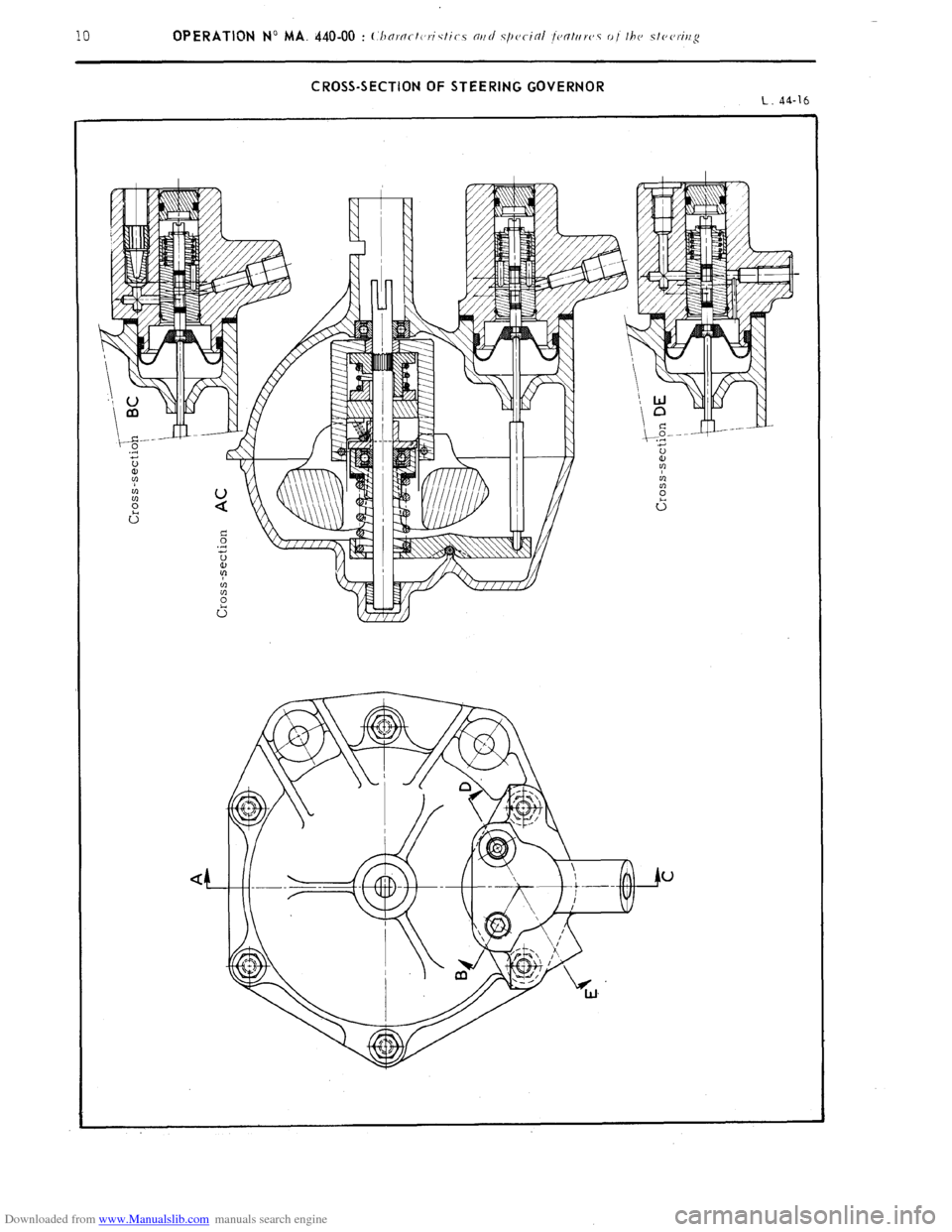
Downloaded from www.Manualslib.com manuals search engine 10 OPERATION No MA. 440-00 : (:hnrnct(,rictic.,s nttd .s/)cjcitil jcntr/rc,.s 01 the stc,c,rirtg CROSS-SECTION OF STEERING GOVERNOR
L.
44-16
Page 272 of 394
Downloaded from www.Manualslib.com manuals search engine Op. MA. 440.00 11
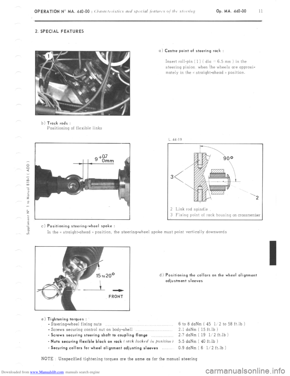
2. SPECIAL FEATURES
a) Centre point of steering rack :
Insert roll-pin ( 1 ) ( dio -: 6.5 mm ) in the
steering pinion when ihe wheels are appraxi-
mutely in the GG siroightohead )B position.
b 1 Track rods :
Positioning of flexible links
4J
a c) Positioning steering-wheel spoke :
2 Link rod spindle
3 Fixing point of rock housing on crossmemker
In the C( straight-ahead )) position, the steering-wheel spoke must point vertically
downwards
d) Positioning the collars on the wheel alignment
adjustment sleeves ---
FRONT
e) Tightening torques :
- Steering-wheel fixing nuts ..,.,........,......,.. .., 6 to 8 daNm ( 45 li 2 to 58 ft.lb j
- Screws securing control nut on body-shell 2.1 daNm ( 15 ft.lb )
. Screws securing steering shaft to coupling flange ,.,,.,,,,,.,.,.,,, 2.7 doNm ( 19 li2 ft.lb )
- Nuts securing flexible block on rack C rnrh lorkc~d iu psi/h) 5.5 doNm ( 40 ft.lb )
-Securing collars for wheel olignmani adjusting sleeves 0.9 daNm ( 6 l/2 ft.lb )
NOTE Unspecified tightening torques are the same as for the manual steering
Page 273 of 394
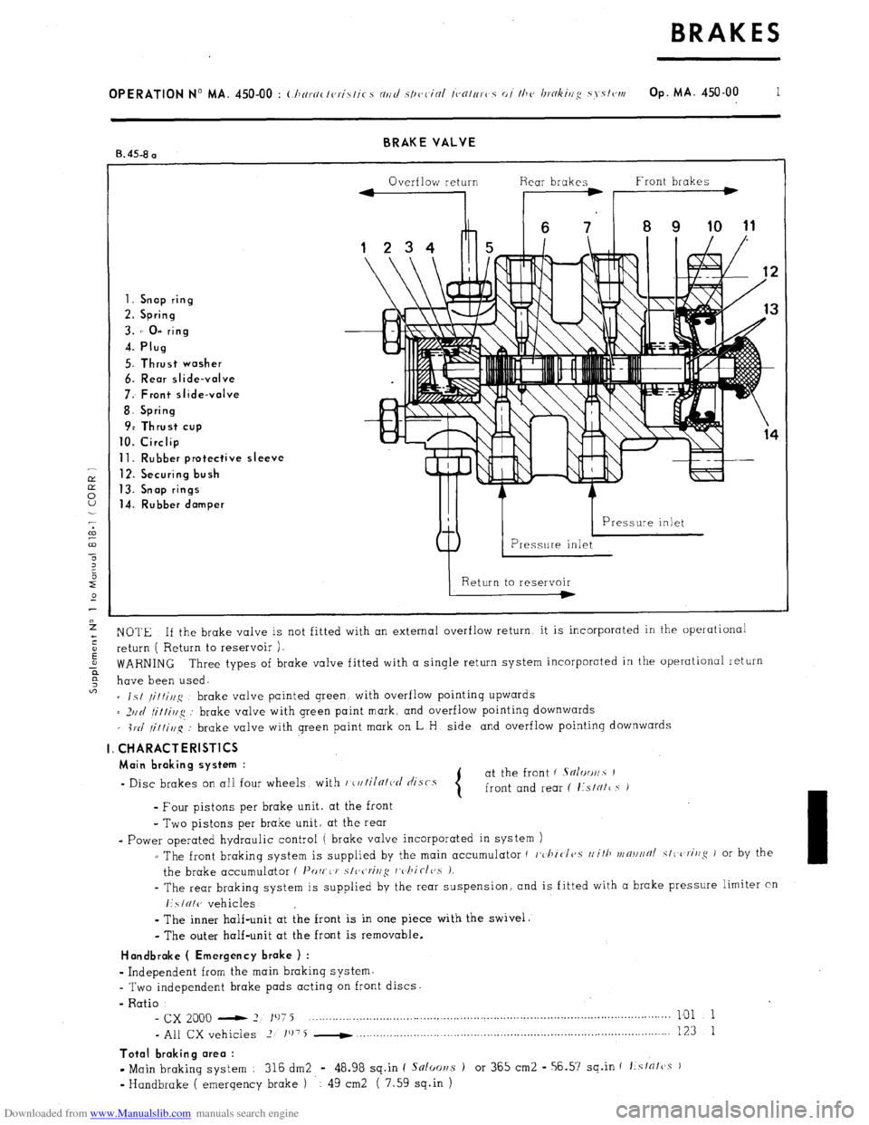
Downloaded from www.Manualslib.com manuals search engine BRAKE VALVE
B. 45-8 a
Overflow return Rear brakes Front brakes
1. Snap ring
2. Spring
3. 1’ 0” ring
4. Plug
5. Thrust washer
6. Rear slide-valve
7: Front slide-valve
8. Spring
9: Thrust cup
10. Circlip
11. Rubber protective sleeve
12. Securing bush
13. Snap rings
14. Rubber damper
NOTE If the brake valve is not fitted with an external overflow return, it is incorporated in the operational
return ( Return to reservoir ).
WARNING Three types of brake valve fitted with a single return system incorporated in the operational return
have been used.
= is/
/it/i//g brake valve painted green with overflow pointing upwards
= _)IIII
fi/tirlg : brake valve with green paint mark, and overflow pointing downwards
_ i1.d
/it/i,l~q’: brake valve with green paint mark on L H side and overflow pointing downwards
I. CHARACTERlSTlCS
Main braking system :
- Disc brakes on all four wheels with r~u/iln/ct/ tlisrs at the front ( Sn/oo//~ I
front and rear ( I:sIN/~ s i
- Four pistons per brake unit. at the front
- Two pistons per brake unit, at the rear
- Power operated hydraulic control ( brake valve incorporated in system )
z The front braking system is supplied by the main accumulator ( c,~l~icI~~.s
rli/ll vrn~l//~/ SIC criug J or by the
the brake accumulator ( I’orr,< J’
s/ccrivg rc,/~iclc,s 1.
- The rear braking system is supplied by the rear suspension. and is fitted with a brake pressure limiter cn
I:SIUI(J vehicles
-
The inner half-unit at the front is in one piece with the swivel.
- The outer half-unit at the front is removable.
Handbroke ( Emergency brake ) :
w
Independent from the main braking system.
- Two independent brake pads acting on front discs.
- Ratio
- cx 2000 - 2 197 j ___._....._..._..._.........,............................................................................... 101 1
- All CX vehicles 2 1’j75 -
. . . . . . 123 1
Total braking area :
- Main braking system : 316 dm2 - 48.98 sq.in ( Snloor~s ) or 365 cm2 - 56.57 sq.in f f:sfrffcss )
v
Handbrake ( emergency brake ) 49 cm2 ( 7.59 sq.in )
Page 274 of 394

Downloaded from www.Manualslib.com manuals search engine FRONT BRAKE UNlT
L. 45-3
3.5 daNm 2.3ta Z5daNm
w-l 25 112 fi.lb 16 1 ’ /2 / to left lb
Page 275 of 394

Downloaded from www.Manualslib.com manuals search engine REAR BRAKE UNIT f .\N/w~//.v )
1.2 to 4.7 doNm
130 l/2 to
34 ft.lb ) face
J
md threod
greased
Page 276 of 394

Downloaded from www.Manualslib.com manuals search engine REAR BRAKE UNIT f /i.\/o/
Page 277 of 394
Downloaded from www.Manualslib.com manuals search engine OPERATION No MA. 450-00 : Ch nrnclcrislics ortd sp~~c-i~l (c~c~trlrc>s 01 the hokiug S SI~IN Op. MA. 450.00 5
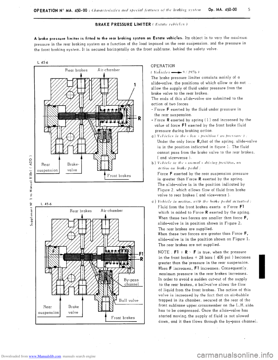
A brake pressure limiter is fitted to the rear braking system on Estate vehicles.
Its object is to vary the maximum
pressure in the rear braking system as a function of the load imposed on the rear suspension and the pressure in
the front braking system. It is secured horizontally on the front subframe, behind the safety valve.
L 45-6
Rear brakes Air-chamber
A
Front brakes
Rear brakes Air-chamber
A A --
7 Front brakes OPERATION
* I
f Vchtclcs - ‘I/]‘,?(, i
The brake pressure limiter consists mainly of a
slide-valve, the positions of which allow or do not
allow the supply of fluid under pressure from the
brake valve to the rear brakes.
The ends of this slide-valve are submitted to the
action of two forces
- Force F
exerted by the fluid under pressure in
the rear suspension.
= Force R
exerted by spring ( 1 ) and increased by the
value of force Fl
exerted by the front brake fluid
pressure during braking action.
a) \‘~~I~i~-/~~s irt Ilte t( lorl r /tr,.silioti f t/o /trc~.s.surc’ )
Under the only force R,that of the spring. slide-valve
is in the position indicated in figure 1. The fluid
cannot pass from the brake valve to the rear brakes,
( and vice-versa ).
Force
F exerted by the rear suspension pressure
is greater than Force R
exerted by the sprinq.
The slide-valve is in the position indicated by
Figure 2. which allows flow of fluid from brake
valve to rear brakes ( and vice-versa ).
c ) Vvhiclc il2 ntotior/. rr,ith 111~’ broke pednl ncl~~fit~~c/ :
Fluid from the front brakes exerts a Force Fl
which is added to Force R exerted by the spring.
When these two forces are smaller than force F,
slide-valve is in position shown in Figure 2.
The rear brakes are supplied.
When these two forces are greater than Force
F,
slide-valve is in the position shown on Figure 1.
The rear brakes are not supplied.
NOTE Fl
+ R -b F is true, when the pressure
in the front brakes + 28 bars ( 406 psi ) becomes
greater than the’pressure in the rear suspension.
When F
increases, Fl increases. Consequently,
maximum pressure in the rear brakes increases.
In order to avoid a sudden cut-out of the supply
to the rear brakes, a ball-valve slows the flow
of liquid from the front brakes. The action of this
valve is increased by the fact that an air-bubble
trapped in its chamber, secured at the rear of the
front subframe upper.crossmember on the L.H. side,
has to be compressed. Once the slide-valve has
started moving, the supply of fluid is not slowed
down, and it then flows through the by-pass channel.
Page 278 of 394
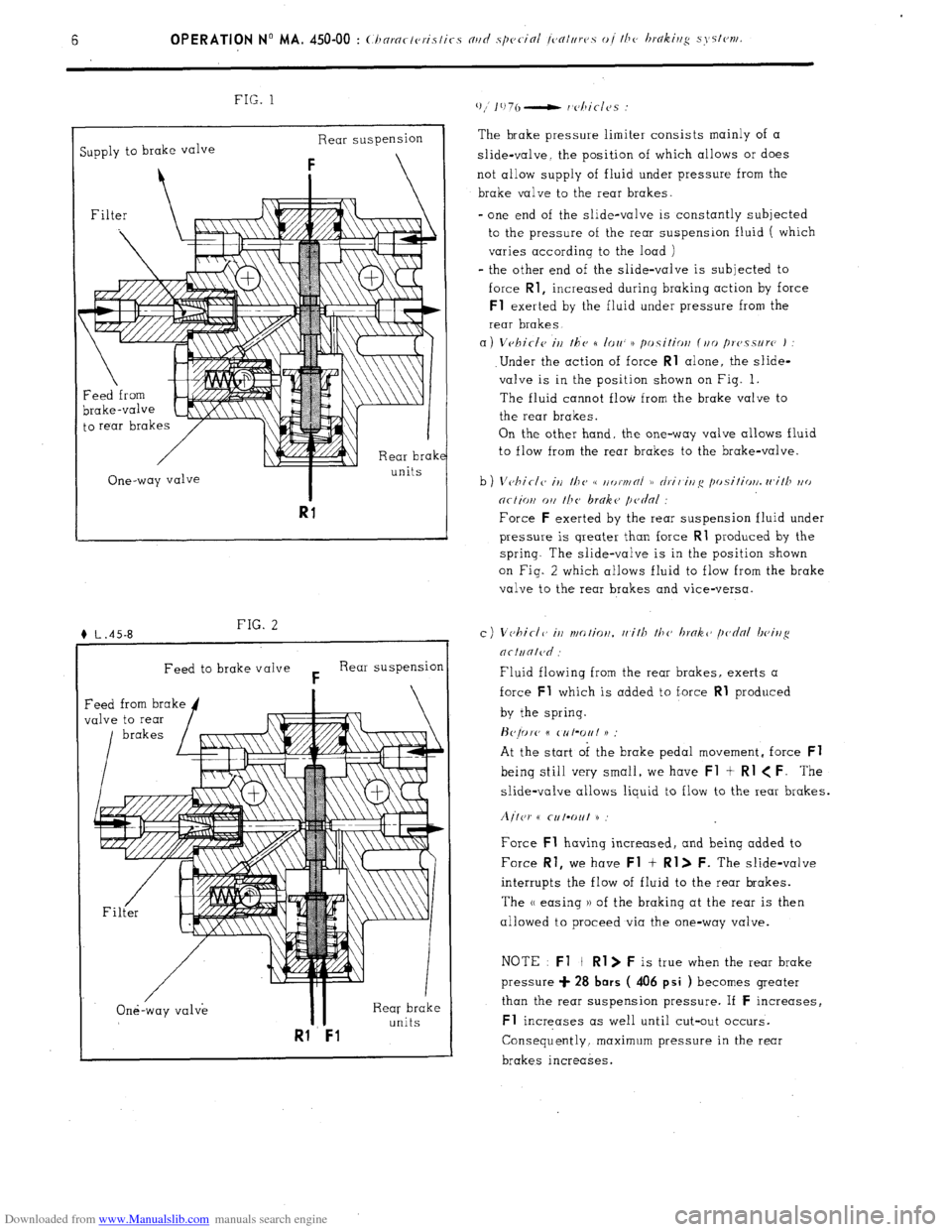
Downloaded from www.Manualslib.com manuals search engine FIG. 1
Supply to brake valve Rear suspension
i
Filter
\--Iii
I
Rear brak
. .
One-way valve
I units
Rl
Feed to brake valve F Rear suspension /
One-way valve II Rear brake
Rl Fl
units The brake pressure limiter consists mainly of a
slide-valve, the position of which allows or does
not allow supply of fluid under pressure from the
brake valve to the rear brakes.
-
one end of the slide-valve is constantly subjected
to the pressure of the rear suspension fluid ( which
varies according to the load )
- the other end of the slide-valve is subjected to
force Rl,
increased during braking action by force Fl
exerted by the fluid under pressure from the
rear brakes
a)
Vvhirlc, irl the n IOU N positiolt (,,o /)rc,.ssurc, )
.Under the action of force Rl alone, the slide-
valve is in the position shown on Fig. 1.
The fluid cannot flow from the brake valve to
the rear brakes.
On the other hand, the one-way valve allows fluid
to flow from the rear brakes to the brake-valve.
Force F
exerted by the rear suspension fluid under
pressure is qreater than force Rl
produced by the
spring. The slide-valve is in the position shown
on Fig. 2 which allows fluid to flow from the brake
valve to the rear brakes and vice-versa.
Fluid flowing from the rear brakes, exerts a
force Fl
which is added to force Rl produced
by the spring.
H~prc 6
CNt’Out 11
At the start of the brake pedal movement, force Fl
being still very small, we have Fl t Rl < F. The
slide-valve allows liquid to flow to the rear brakes.
Aitcr t( CIIIW~~ H
Force Fl
having increased, and being added to
Force Rl,
we have Fl + Rl> F. The slide-valve
interrupts the flow of fluid to the rear brakes.
The (( easing )) of the braking at the rear is then
allowed to proceed via the one-way valve.
NOTE : Fl
+ Rl> F is true when the rear brake
pressure + 28 bars
( 406 psi ) becomes greater
than the rear suspension pressure. If F
increases, Fl
Increases as well until cut-out occurs.
Consequently, maximum pressure in the rear
brakes increases.
Page 279 of 394
Downloaded from www.Manualslib.com manuals search engine OPERATION N” MA. 450-00
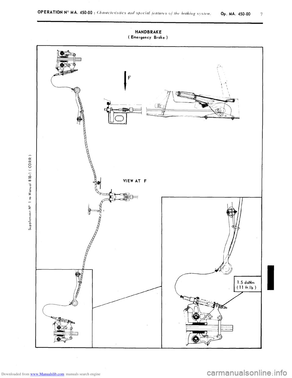
HANDBRAKE
( Emergency Brake )
Page 280 of 394
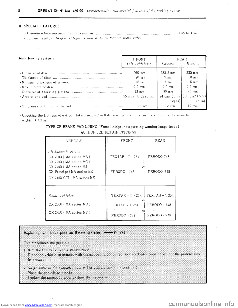
Downloaded from www.Manualslib.com manuals search engine II. SPECIAL FEATURES
- Clearance between pedal and brake-valve
” ..: 0.05 to 3 mm
_ Stoplamp switch ,: Inal/) VII/S/ lislli c/c .soo,~ 05 [I(‘~~II /~//c-/~c,s IJTO~(~ /,fl// (J Main braking system :
- Diameter of disc .......................................................................... 260 mm
- Thickness of disc .........................................................................
20 mm
s Minimum thickness after wear .................................................... 18 mm
_ Max run-out of disc ...................................................................
0 2 mm
- Diameter of operatinq pistons ....................................................
42 mm
- Area of one pad ............................................................................
55 cm2 (8 52sq.in)
- Thickness of lining on the pad .,,_.,..,_.__.._.._,....,.......................... 115mm
233 5 mm 235 mm
9 mm 18 mm
7 mm 16 mm
0.2 mm 0 2 mm
30 mm 40 mm
24 cm2 (3.72 (36cm2 (5.5
sq.in) sq.in
12 mm
12 mm
- Checking the flatness of a disc take a reading in 8 different points the results should be the same to
within : 0.02 mm
TYPE OF BRAKE PAD LINING (Front linings incorporating warning-lamps leads
j
AUTHORISED REPAIR FITTINGS
VEHICLE
All Snlow L’c~l,ir-ll 5
CX 2000
( MA series MB )
CX 2200 ( MA series MC )
CX 2400 ( MA series MJ )
CX Prestiqe (MA series MK )
CX 2400 GTI ( MA series ME )
CX 2000 ( MA series MD )
CX 2400 ( MA series MF )
8
1
FRONT REAR
TEXTAR- T .= 254 FERODO 748
or
FERODO e 748
I FERODO 748
TEXTAR - T - 254 1 TEXTAR -T2-54
or
TEXTAR - T 254
I FERODO - 748
or
FERODO - 748
I FERODO r 748