engine Citroen CX 1981 1.G Workshop Manual
[x] Cancel search | Manufacturer: CITROEN, Model Year: 1981, Model line: CX, Model: Citroen CX 1981 1.GPages: 394
Page 301 of 394
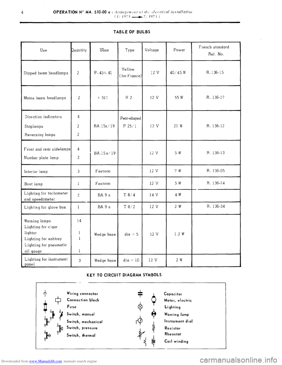
Downloaded from www.Manualslib.com manuals search engine TABLE OF BULBS
Use Juantity ‘B&e
Type Voltage Power French standard
Ref. No.
Yellow
Dipped beam headlamps 2 P. 45t. 41 R.
( for France) 12 v 40/45 w 136-15
Mains beam headlamps 2 x 511 H2 12 v 55 w R. 136-17
Direction indicators 4
Pear-shaped
Stoplamps 2 BA.l5s/ 19 P 25/l 12 v 21 w R. 136-12
Reversing lamps 2
Front and rear sidelamps 4
BA.l5s/ 19 12 v 5w R. 136-13
Number plate lamp 2
Interior lamp 3 Festoon 12 v 7w R. 136-05
Boot lamp 1 Festoon 12 v 5w R. 136-14
Lighting for tachometer 2 BA 9 s T
8/4 14 v 4w
and speedometer
Lighting for glove box 1 BA 9 s T 8/2 12 v 2w R. 136-34
Warning lamps 14
Lighting for cigar
lighter 1
Wedge base dia == 5 12 v 1..2 w
Lighting for ashtray 1
Lighting for pneumatic
oil gauge I
Lighting for instrument
3
panel Wedge base dia = 10 12 v 2w
KEY TO CIRCUIT DIAGRAM SYMBOLS
I Wiring connector
Q + Capacitor
0 Connection black Motor, electric
Fuse
b b Lighting
d ? 16 Switch, manual Warning lamp
IO Switch, mechanical Instrument dial
? d
Switch, pressure Resistor
b ?
I@ )#
Switch, thermal Rheostat
P
Coil winding
Page 302 of 394

Downloaded from www.Manualslib.com manuals search engine
Page 303 of 394

Downloaded from www.Manualslib.com manuals search engine
Page 304 of 394
Downloaded from www.Manualslib.com manuals search engine OPERATION No MA. 510-00 b : A. ~rai~gc~mc~r~l oi t/7(’ c~lc~ctrical itfstallation
i I,07jf 9, 1975 J Op. MA. 510-00 b 1
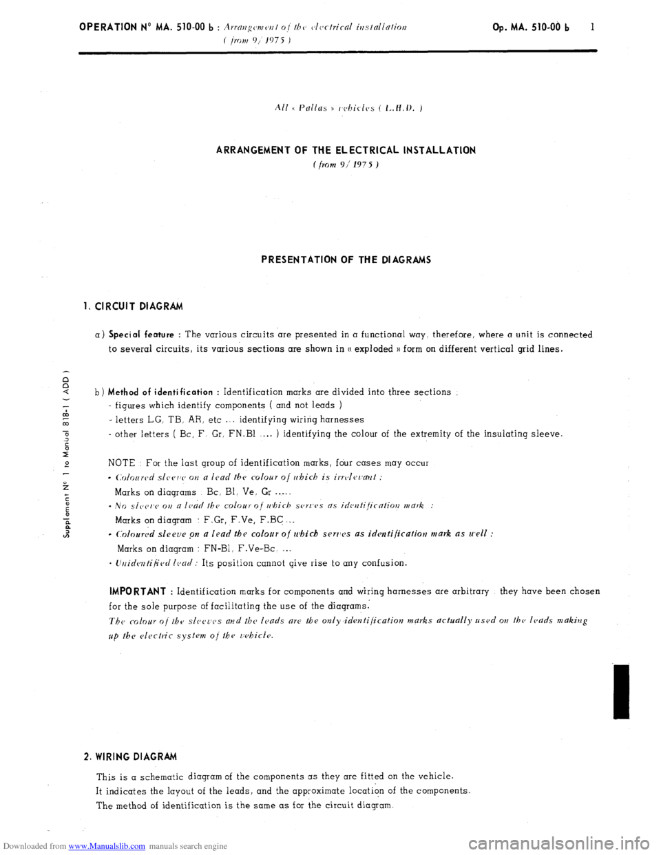
ARRANGEMENT OF THE ELECTRICAL INSTALLATION
f from 9i 197 5 ) PRESENTATION OF THE DIAGRAMS
1, CIRCUIT DIAGRAM
a) Special feature : The various circuits are presented in a functional way, therefore, where a unit is connected
to several circuits, its various sections are shown in CC exploded )) form on different vertical grid lines. i
b) Method of identification : Identification marks are divided into three sections
‘; - figures which identify components ( and not leads )
co
co - letters LG. TB. AR. etc .“. identifying wiring harnesses
0
.3 - other letters ( Bc: F Gr, FN.Bl .-.. ) identifying the colour of the extremity of the insulating sleeve.
c
r”
e NOTE For the last group of identification marks, four cases may occur
2
l C0lo~red slcrrv on a lead the colour oj r&i& is irrvler~a~~t :
Marks on diagrams Bc, Bl. Ve. Gr . . . .
c
i - NO slc~er,c 011 a ledd the colour of rr~hich .ser~‘es as ideutijicatiotl mark. :
2 Marks on diagram : F.Gr, F.Ve, F.BG . . .
l2 c
Coloured sleeve pn a lead the colour o/ which serr1c.s as identification mark as well :
Marks on diagram : FN-Bl. F.Ve-Bc. . . .
- Urlidcntijied lead : Its position cannot give rise to any confusion. IMPORTANT
: Identification marks for components and wiring harnesses are arbitrary they have been chosen
for the sole purpose of facilitating the use of the diagrams.
The colour of the sl~~e~-cs arld the leads are the only.identijication marks actually used ow the leads making
up the electric system oj the r;ehic!e. 2. WIRING DIAGRAM
This is a schematic diagram of the components as they are fitted on the vehicle.
It indicates the layout of the leads, and the approximate location of the components.
The method of identification is the same as for the circuit diagram.
Page 305 of 394
Downloaded from www.Manualslib.com manuals search engine 2 OPERATION No MA. 510-00 b : Arratzgement of the electrical installation
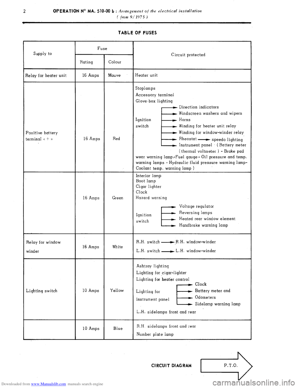
( jhrl 9/1975 ) TABLE OF FUSES
Supply to
lelay for heater unit
‘ositive battery
erminal (( + 1) Fuse
Circuit protected
Rating Colour
16 Amps Mauve Heater unit
Stoplamps
Accessory terminal
Glove-box lighting
E Direction indicators
Windscreen washers and wipers
Ignition Horns
switch Winding for heater unit relay
Winding for window-winder relay
16 Amps Red Rheostat
- speed0 lighting
Instrument panel : ( Battery meter
( thermal voltmeter ) - Brake pad
wear warning lamp.-Fuel gauge- Oil pressure and temp.
warning lamps - Hydraulic fluid pressure warning lamp-
Coolant temp. warning lamp )
Interior lamp
Boot lamp
Cigar lighter
Clock
16 Amps Green Hazard warning
E Voltage regulator
Ignition Reversing lamps
switch Heated rear window element
Handbrake warning lamp
Relay for window
winder 16 Amps White R.H. switch u,R.H. window-winder
L.H. switch - L.H. window-winder
Lighting switch Ashtray lighting
Lighting for cigar-lighter
Lighting for heat’er control
Clock
10 Amps Yellow
Lighting for Battery meter and
instrument panel
E. Odometers
Sidelamp warning lamp
L.H. sidelamps front and rear
10 Amps Blue R,H. sidelamps front and rear
Number plate lamp Cl RCU I T DI AG RAM
Page 306 of 394

Downloaded from www.Manualslib.com manuals search engine
Page 307 of 394

Downloaded from www.Manualslib.com manuals search engine
Page 308 of 394
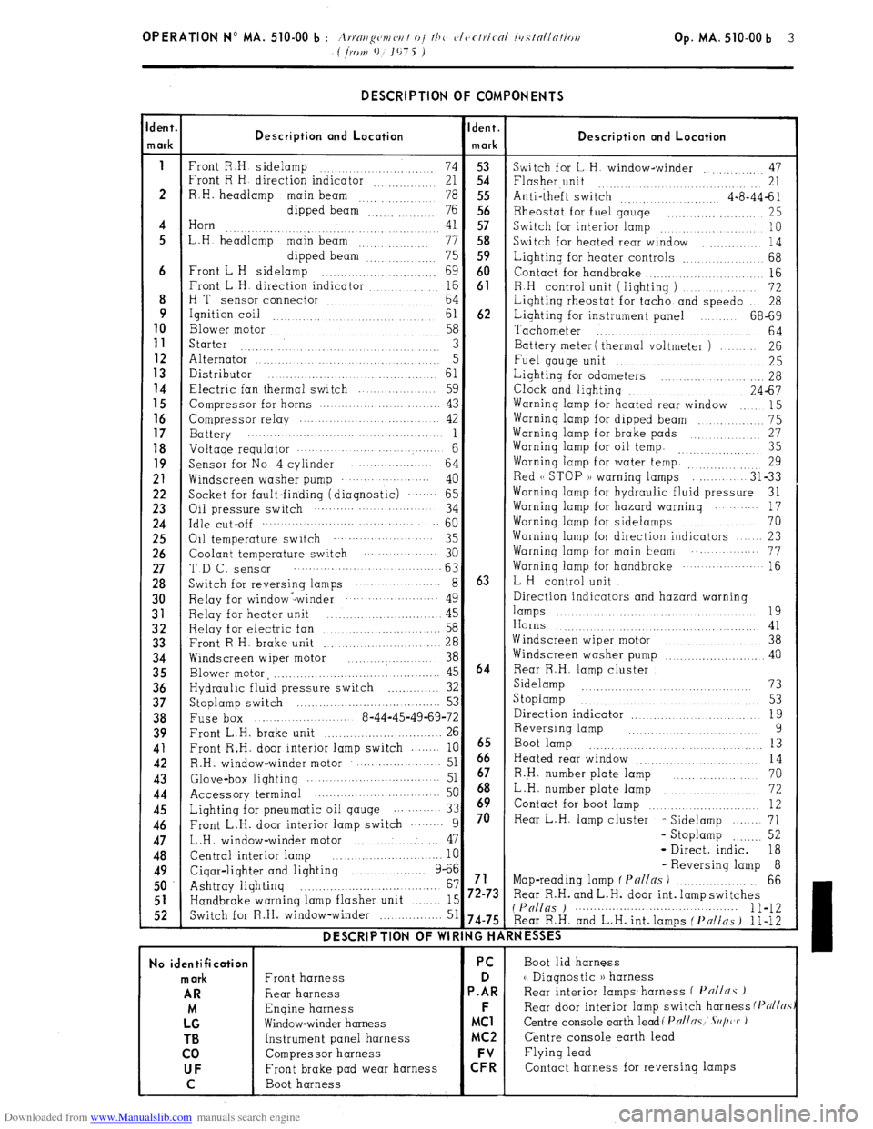
Downloaded from www.Manualslib.com manuals search engine DESCRIPTION OF COMPONENTS
dent.
Ident.
Description ond Location
n ark Description and Location
mark
1
Front R.H sidelamp
74 53
Switch for L.H. window-winder .,, 47
Front R H direction indicator
21 54 Flasher unit
.... 21
2 R.H. headlamp
main beam
78 55 Anti-theft switch
4-a-44-61
dipped beam
76 56 Rheostat for fuel gauqe
,.. 25
4 Horn
41 57
. Switch for interior lamp .,. 10
5 L.H headlamp main beam
.., .., ,.. 77 58
Switch for heated rear window
14
dipped beam”: 75 59 Lighting for heater controls _.. 68
6 Front L H sidelamp
.,. 69 60
Contact for handbrake .._....
16
Front L.H. direction indicator ,.... ._. _._.. 16 61
8 R.H control unit (lighting )
72
H T
sensor connector ,. 64
Lighting rheostat for tacho and speed0
28
9
Ignition coil ,.,
61 62 Lighting for instrument panel 68-69
10
Blower motor 58
Tachometer
.,.
64 11
Starter 3 Battery meter ( thermal voltmeter ) 26 12 Alternator ..I
5
Fuel gauqe unit 25 13
Distributor
61 14 Lighting for odometers _. 28 Electric fan thermal switch 59
Clock and lighting .._.. .,. 24-67
15
Compressor for horns 43 Warning lamp for heated rear window
15 16 Compressor relay 42 Warning lamp for dipped beam
_.. 75 17
Battery 1 Warninq lamp for brake pads 27 18 Voltage regulator . . . . . . . . . . 6 Warning lamp for oil temp. ,,_.. 35
19
Sensor for No 4 cylinder
64 Warning lamp for water temp. ..._.,,, ,,,,. 29 21
Windscreen washer pump ... .. ......
40 Red (( STOP )) warning lamps
31-33 22
Socket for fault-finding (diagnostic) .‘.‘.... 65 Warninq lamp for hydraulic fluid pressure
31 23
Oil pressure switch 34 Warning lamp for hazard warning
17 24 Idle cut-off .._........ 60
Warning lamp for sidelamps
70 25
Oil temperature switch 35 Warning lamp for direction indicators 23 26
Coolant temperature switch 30 Warninq lamp for main beam .‘..... 77 27 ‘I’D f-, SenSOr 63
Warning lamp for handbrake ... .‘........-.. 16 28
Switch for reversinq lamps ... ... ....... 8 63 L H control unit 30
Relay for window -winder ... ... .‘........ 49 Direction indicators and hazard warning 31
Relay for heater unit 45 lamps .,. .,...._ .,. .._ 19
.,. .._.......... 32
Relay for electric fan 58 Horns 41 33
Front R H. brake unit
.._.. 28 Windscreen wiper motor
..,.... 38 34
Windscreen wiper motor
_.............. 38 Windscreen washer pump
.._...... 40 35
Blower motor, ,._..._._....._._..._........ 45 64 Rear R.H. lamp cluster 36
Hydraulic fluid pressure switch _..._......... 32 Sidelamp .._...... 73
37
Stoplamp switch 53 S toplamp
_. _. _. _. _. _. _. 53
.._..............
38
Fuse box 8-44-45-49-69-72 Direction indicator
19
_.. _._.. 39
Front L.H. brake unit
. .._.._............... 26 Reversing lamp 9 41
Front R.H. door interior lamp switch 10
6665 Boot lamp .._. ._. 13
42
R.H. window-winder motor ..- 51 Heated rear window
14 43
Glove&or lightinq .._............ 51 67 R.H. number plate lamp 70
44
Accessory terminal 50 68 _..,......... L.H. number plate lamp
72 45
Lighting for pneumatic oil qauge 33 h9 Contact for boot lamp .._.. .._. .._........ 12 46
Front L.H. door interior lamp switch 9 70 Rear L.H. lamp cluster
- Sidelamp
71 47
L.H. window-winder motor ..: 47 - Stoplamp .._._... 52
48
Central interior lamp
10 - Direct. indic. 18 49
Cigar-lighter and lighting 9-66 - Reversing lamp 8
.._....
50 Ashtray lighting 67 71 Map-reading lamp f Pnl/ns ) .._..._....._.
66
_._......._...................... 51
Handbrake warning lamp flasher unit .._._.._ 15 72-73 Rear R.H. and L.H. door int. lamp switches 52
Switch for R.H. window-winder _..._.. 51 (P(/llgs ) 1 l-12 74-75 Rear R.H. and L.H. int. lamps ( f’nlins ) 1 l-12 DESCRIPTION OF WIRING HARNESSES
No identification PC
Boot lid harness mark
Front harness D <( Diagnostic )) harness AR
Rear harness P.AR Rear interior lamps.harness f I’n//nc )
M Engine harness F
Rear door interior lamp switch harness (Pflj/~.s LG
Window-winder harness MC1 Centre console earth lead( Pall~.~,’ S~/jczr ) TB
Instrument panel harness MC2 Centre console earth lead
co Compressor harness Flying lead UF
Front brake pad wear harness C: Contact harness for reversing lamps
C Boot harness
Page 309 of 394
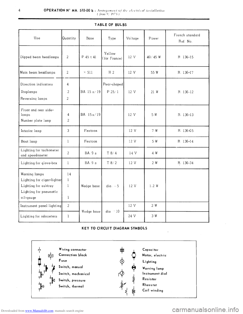
Downloaded from www.Manualslib.com manuals search engine 4 OPERATION No MA. 510-00 b : it ..n < ,I ,/“c’mc’,, I oi Ill<’ ~‘IVfl,.iC NI iilClNllNtiorl
( ~KJI~I l), 107 5 j
TABLE OF BULBS
French standard
Ref No.
R 136-15 Type Voltage Power luantity Use
Dipped beam headlamps
2
Base
P.45 t 41 Yellow
for France) 12 v
40/ 45 w
x 511 H2 12 v 55 w R. 136-17 2
--
4
2
2 Main beam headlamps
Direction indicators
Stoplamps
Reversinq lamps
Front and rear side-
lamps
Number plate lamp ‘ear-shape<
P 25/ 1 3A 1
S/ 9
12 v 21 w R 136-12
3A 15s/ 9
12 v
5w R. 136-13
R. 136-05
I Interior lamp Festoon 12 v 7w
Festoon
12 v 5W R 136-14 Boot lamp
4v 4w BA.9 s
BA 9 s T 8/4
T 8/2 1 12 v 2w R. 136-34
Warning lamps
Lighting for cigar-light
Lighting for ashtray
Lighting for pneumatic
oil-gauge
Instrument panel lighti
Liqhting for odometers
I I dia. -5 12 v 1.2 w
Wedge base
Wedge base dia 10
2 12 v 2w
1 24 V 3w
KEY TO CIRCUIT DIAGRAM SYMBOLS +
Wiring connector
Capacitor
4 0 6V Connection block
Motor, electric
Fuse
6 b Lighting
u Switch, manual
A Y Warning lamp
b Switch, mechanical Instrument dial
? d
)# Switch, pressure Resistor
b Y
IQ Switch, thermal Rheostat
0 Coil winding
Page 310 of 394

Downloaded from www.Manualslib.com manuals search engine