wheel Citroen CX 1981 1.G Repair Manual
[x] Cancel search | Manufacturer: CITROEN, Model Year: 1981, Model line: CX, Model: Citroen CX 1981 1.GPages: 394
Page 286 of 394
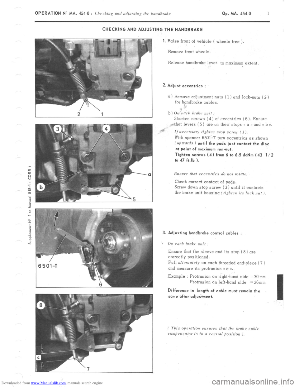
Downloaded from www.Manualslib.com manuals search engine OPERATION No MA. 454-O : Lhcckiu~ avd adjnsfbrR fhe bandbrake op. MA. 454-u I CHECKING AND ADJUSTING THE HANDBRAKE
1.
Raise front of vehicle ( wheels free ).
Remove front wheels.
Release handbrake lever to maximum extent 2. Adjust eccentrics :
a) Remove adjustment nuts ( 1 ) and lock-nuts (2.)
for handbrake cables.
b ) O,,,‘varh hmokt~ ,,rzit :
Slacken SCI~WS (4) of eccentrics ( 6 ). Ensure
With spanner 6501-T turn eccentrics as shown f rrpu,ards ) until the pads just contact the disc
at point of maximum run-out.
Tighten screws (4) from 6 to 6.5 daNm (43 l/2
to 47 ft.lb ).
Check correct contact of pads.
Screw down stop SCI~W (3) until it contacts
the brake unit housing ( tighfrn its lock EN! 1, 3. Adjusting hondbrake control cables :
, On rnrh hrnkc ,,,, if:
Ensure
Pull alfcmnf~~iy on each threaded end-piece (7 )
ond measure its protrusion (< c 1).
.Example : Protrusion on right-hand side = 30 mm
Protrusion on left-hand side = 26mm Difference in length of cable must remain the
some after adiuitment.
Page 287 of 394
Downloaded from www.Manualslib.com manuals search engine OPERATION No MA. 454-O : Ch ec tzg and a&sting the handbrakc k’
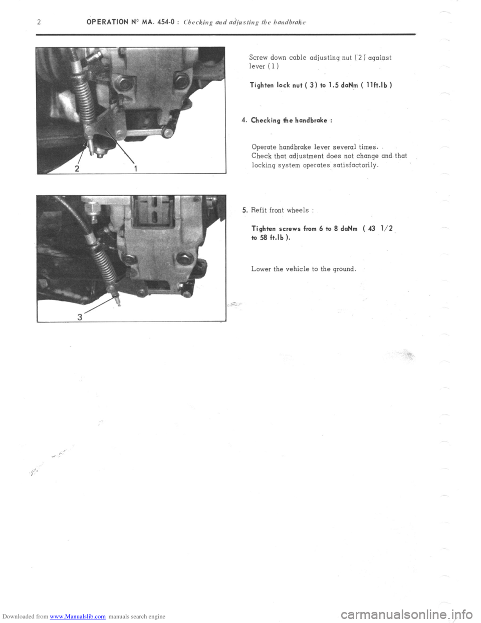
Screw down cable adjusting nut (2) against
lever ( 1) Tighten lock nut ( 3) to 1.5 doNm ( llft.lb)
4. Checking tie handbrake :
Operate handbrake lever several times.
Check that adjustment does not change and that
locking system operates satisfactorily.
5. Refit front wheels : Tighten screws from 6 to 8 daNm ( 43 l/2,
ta 58 ft.lb ).
Lower the vehicle to the ground.
Page 329 of 394
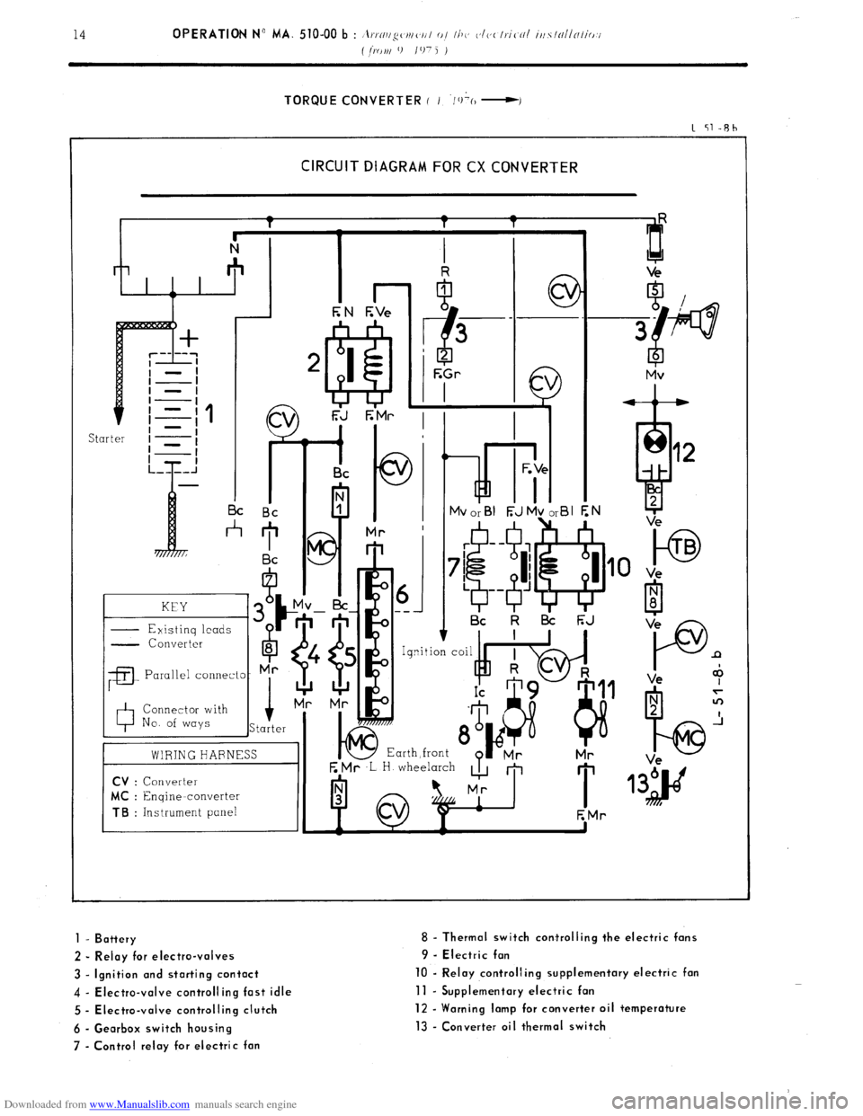
Downloaded from www.Manualslib.com manuals search engine TORQUE CONVERTER ( I ‘/+(I -I
1 51-Rh
CIRCUIT DIAGRAM FOR CX CONVERTER
kd i- I I I c
I I Bc Bc
*
KEY
- Existinq leads G
- Converter
6
8
;a
Parallel connecto- Mr
0 Connector with
No. of ways i
Starter
01 ---
I Bc k l3i F;J
E Mr ,L H wheelarch
A m
I 1
EMr
to TB
Ve
P n
Ve +
1 - Battery
2 - Relay for electro-valves
3 - Ignition and starting contact
4 - Electra-valve controlling fast idle
5 - Electra-valve controlling clutch
6 - Gearbox switch housing
7 - Control relay for electric fan 8 - Thermal switch corrtrolling the electric fans
9 - Electric fan
10 - Relay controlling supplementary electric fan
11 - Supplementary electric fan
12 - Warning lamp for converter oil temperature
13 - Converter oil thermal switch
Page 333 of 394
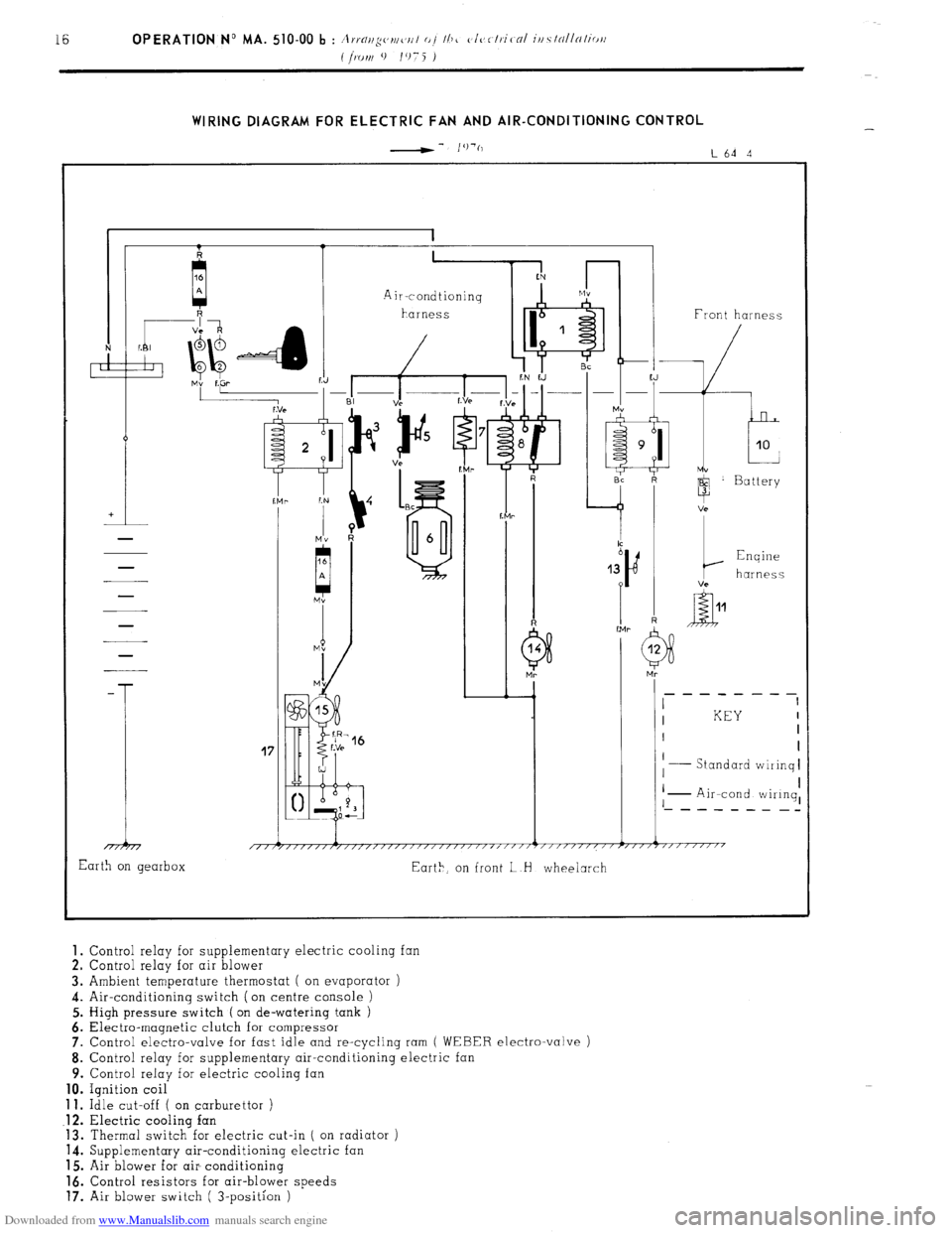
Downloaded from www.Manualslib.com manuals search engine WIRING DIAGRAM FOR ELECTRIC FAN AND AIR-CONDITIONING CONTROL
-- I’)‘(,
L64 4
41 1 1 Front harness
-
T
17
I KEY I
I I
I
Standard wiiinq I
I I
I I
I - Air-cond wiIinq, ‘- - - - - - - _-
1 i 1 1 1
/,/r/////,/,,,,/,//////~////~‘/‘~””’~”””””~””7”“““’
Earth on gearbox
Eart>, on front L H wheelarch 1.
Control relay for supplementary electric cooling fan
2. Control relay for air blower
3. Ambient temperature thermostat ( on evaporator )
4. Air-conditioning switch (on centre console )
5. High pressure switch ( on de-watering tank )
6. Electra-magnetic clutch for compressor
7. Control electro-valve for fast idle and re-cycling ram
( WEBER electro-valve )
8. Control relay for supplementary air-conditioning electric
9. Control relay for electric cooling fan 10.
Ignition coil 11.
Idle cut-off ( on carburettor ) .12.
Electric cooling fan
13. Thermal switch for electric cut-in ( on radiator )
14. Supplementary air-conditioning electric fan
15. Air blower for air- conditioning 16.
Control resistors for air-blower speeds 17.
Air blower switch ( 3-position )
Page 351 of 394
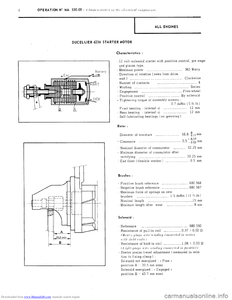
Downloaded from www.Manualslib.com manuals search engine DIJCELLIER 6236 STARTER MOTOR
Ch aracteristics :
Battery
+ E xc,-.L
I ALL ENGINES
12 volt solenoid starter with positive control, pre-enga-
ged pinion type.
- Maximum power ,.,..................................... 965 Watts
Direction of rotation (seen from drive
end ) ,.,_,.,.,. ..,.,...,.,. ,.,.,.,...._ . . . . .._...... .,.,. Clockwise
Number of contacts ._.,.,.,.,.,.,_........ ..,.,.,............. 4
- Winding ._.,.,......... ,.,.,.,_......,.,.....,.,...............~... Series
- Engagement ,~.,.,...,... ,.,............... . Free-wheel
- Positive control ,.,.,. . . . . . . . . . . ..,.,.,... By solenoid
- Tightening torque of assembly screws :
0.7 daNm ( 5 ft,lb)
Front bearing : internal d . . . 12 mm
- Rear bearing : internal <,!J 12
mm
Self -lubricating bearings ( no greasing ). Rotor :
Diameter of armature ,_,.,.,. .,. _..._.... 56.8
8.11 mm
‘- Clearance ... . . . . . . . . . . . .
t 0.17 0.5 e005mm
- Nominal diameter of commutator ._._...,.,.,. 32.25 mm
- Minimum diameter of commutator after
rectifying . . . . . . . . . . . . . . . . . . . . . 30.25 mm
End float (flexible washer) ,.........,.,.,..._.....,. 0.5 mm Brushes :
Positive brush reference ._._.,.,... ,..... . . . . . 680 568
Negative brush reference ..,.,.,.,.,.,.,............... 680 567
Maximum force of springs on new
brushes . . . . . . . . . . . . . . . . . . . . . . . . . . . . . 1.5 daNm (11 ft.lb)
Nominal length . . . . ._.............,...............~. 15 mm
Minimum length after wear ., . . . . . . . . 8
mm Solenoid :
- Reference ._. ,.,..............~........................ .,.. 680 592
Resistance of pull-in coil ,_...,.,.........,. 0.37 i 0.02 Q
(lfc~or~j-gctup (L irc~‘rc iltdittg co~~rtcftc~d it/ series
11 ill7 /ic,ld coils I
Resistance of hold-in coil ,_...,...,.......... 1 .08 ? 0.03 Q
( I.igh!-~oll~c~ /l~iF(, I, ittditlg cottrtc~cl<~d
it/ parnllr~l )
- Starter pinion travel adjustment (measured in rela-
tion to fixing clamp) :
Solenoid not energized : (( Free H
position A 30.5 mm maxi
Solenoid energized : u Engaged u
position B 7 43.7 mm maxi
Page 352 of 394
Downloaded from www.Manualslib.com manuals search engine 1 ALL ENGINES
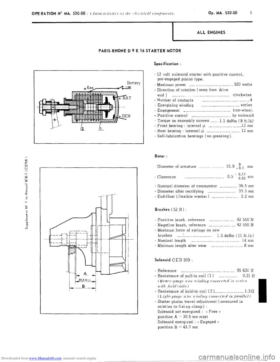
PARIS-RHONE D 9 E 16 STARTER MOTOR
Battery Specification :
- 12 volt solenoid starter with positive control,
pre-engaged pinion type.
- Maximum power ,..... ,................................. 920 watts
- Direction of rotation ( seen from drive
end ) ., . . . ._..,.,...,.,..................... clockwise
- Number of contacts __..... . . . . . . . . . . . . . . . . . . . . . . . . . . . 4
- Energizing winding . . . . . . . . . . . . . . . . . . . . . . . . . . . . . . . . . . series
- Enqagement ,“...,.,.........,.,.............,......... free-wheel
- Positive control ._.,.,.,.,.,.,.......,.,.,....... . by solenoid
- Torque on assembly screws . . . . . . 1.1 daNm (8 ft.lb)
- Front bearing : internal 4 ,..._.,.....,...,.,.,. _....._. 12 mm
- Rear bearing : internal $I ._...,...,...,.,.,.,. ,.....,. 12 mm
- Self-lubrication bearings ( no greasing ). Rotor :
Diameter of armature . . . . . . . . . . . . . . . 55.9 - ;.I mm
- Clearance _.......................... . . . . . . 0.5 ’
0.17
0.05 mm
- “Jominal diameter of commutator . . . . . . . . . . . . . . . . 36.5 mm
- Diameter after rectifying ,.....,................... 35.5mm
- End-float (flexible washer) ,....._.,... . . . 2.2 mm Brushes (52
R) :
- Positive brush, reference . . . . . . . . . . . . . . 92 550 N
- Negative brush, reference ,...,.,.,.,.,. ,.,.,. . . . 92 550 N
- Maximum force of springs on new
brushes ,... ..I. . ,. ,. . . . ..,......... 1.5 daNm (11 ft.lb)
- Nominal length
,... . . . . . . .., . . . . . . . .,......... 14 mm
- Minimum length after wear . . . . . . . ..,......... 8 mm Solenoid
CED 509 :
- R.eference . . . . . . . . . . . . . . . . . . . . . . . . . . . . . . . . . . . . . . . ,.,. 95 631 U
- Resistance of pull-in coil (1 ) . . . . . 0.21 Q
(Heaz’y-gauge wire IL’i?/dirzg cotlucctcd iu .sc,ricJs
with field coils )
- Resistance of hold-in coil ( 2 ) . . . . . . . . . . . . . . . . . . . . . . . . . . 1.3 Q
( Light-gc7zigc wire’ 11 itlrliug conwctcrl in pdrallrl )
- Starter pinion travel adjustment (measured in
relation to fixi ng clamp ) :
Solenoid not energized : (( Free ))
position A = 30.5 mm maxi
Solenoid energized : (( Engaged 1)
position B = 43.7 mm