wheel Citroen CX 1983 1.G User Guide
[x] Cancel search | Manufacturer: CITROEN, Model Year: 1983, Model line: CX, Model: Citroen CX 1983 1.GPages: 394
Page 60 of 394
Downloaded from www.Manualslib.com manuals search engine OPERATION N” MA. 100-00 : (:hnractc,ri.stics arid specinl j(,atrlres o,/ the> cl,gi?lcJ. Op. MA. 100-00 1
9
4. Barrels and pistons :
a)
Barrels :
cast iron wet-type removable barrels.
b) Pistons :
-- autothermic pistons, in lead-coated alpax,
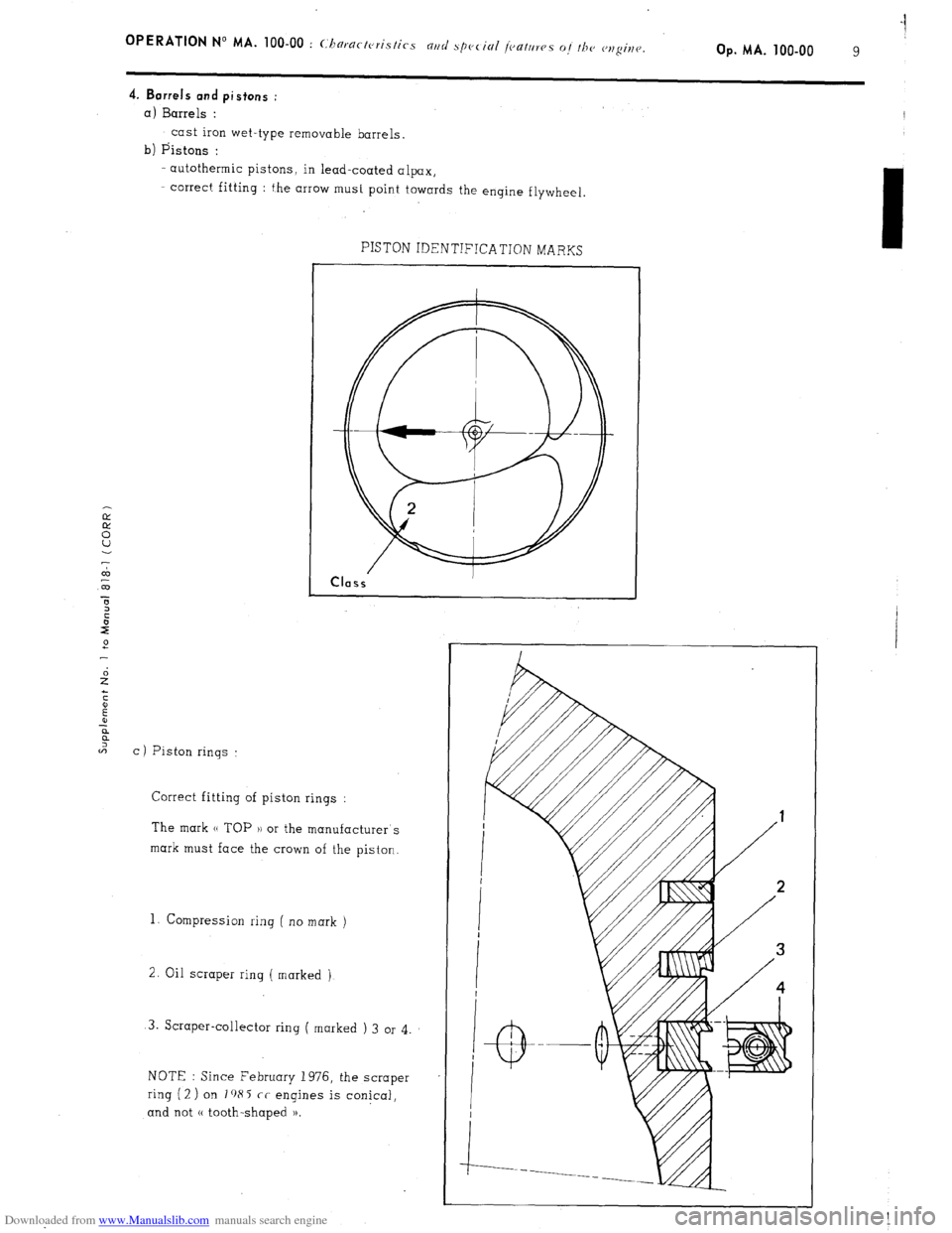
- correct fitting : the arrow must point towards the engine flywheel
7
co
m
C ) Piston rings : PISTON IDENTIFICATION MARKS
Correct fitting of piston rings :
The mark (( TOP 1) or the manufacturer’s
mark must face the crown of the piston.
1. Compression ring ( no mark )
2. Oil scraper ring ( marked )
3. Scraper-collector ring ( marked ) 3 or 4
NOTE : Since February 1976, the scraper
ring (2 ) on I a85 cc engines is conical,
and not (( tooth-shaped )).
Page 66 of 394
Downloaded from www.Manualslib.com manuals search engine OPERATION No MA. 100-00 : Characteristics and special features of the engine. Op. MA. 100.00 15
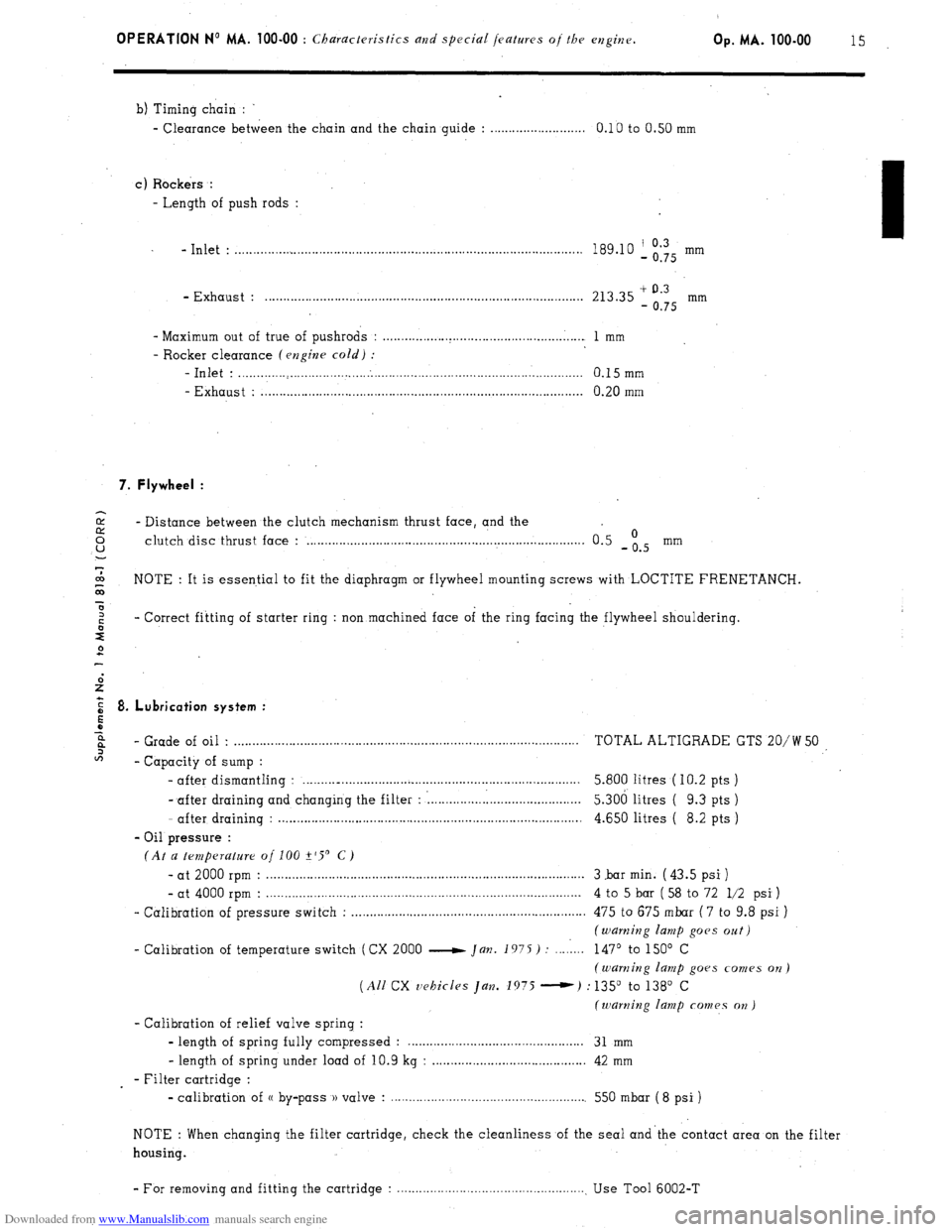
b) Timing chain :
- Clearance between the chain and the chain guide : . . . . . . . . . . . . . . . . . . . . . . . . . . 0.10 to 0.50 mm
c) Rockers :
- Length of push rods :
- Inlet : . . . . . . . . . . . . . . . . . . . . . . . . . . . . . . . . . . . . . . . . . . . . . . . . . . . . . . . . . . . . . . . . . . . . . . . . . . . . . . . . . . . . . . . . . . . . . . 189.10 ‘, Og’Q5 mm
- Exhaust : . . . . . . . . . . . . . . . . . . . . . . . . . . . . . . . . . . . . . . . . . . . . . . . . . . . . . . . . . . . . . . . . . . . . . . . . . . . . . . . . . . . . . . . 213.35 + 0.3
- 0.75 mm
- Maximum out of true of pushrods : . . . . . . . . . . . . . . . . . . . . . . . . . . . . . . . . . . . . . . . . . . . . . . . . . . . . . . . 1 mm
- Rocker clearance (engine cold) :
-Inlet : . . . . . . . . . . . . . . . . . . . . . . . . . . . . . . . . . . . . . . . . . . . . . . . . . . . . . . . . . . . . . . . . . . . . . . . . . . . . . . . . . . . . . . . . . . . . . . 0.15mm
- Exhaust : . . . . . . . . . . . . . . . . . . . . . . . . . . . . . . . . . . . . . . . . . . . . . . . . . . . . . . . . . . . . . . . . . . . . . . . . . . . . . . . . . . . . . . . . 0.20 mm
7. Flywheel :
2 - Distance between the clutch mechanism thrust face, and the 0 u clutch disc thrust face : . . . . . . . . . . . . . . . . . . . . . . . . . . . . . . . . . . . . . . . . . . . . . . . . . . . . . . . . . . . . . . . . . . . . . . . . . . . . 0.5 -is mm
7
co
G NOTE : It is essential to fit the diaphragm or flywheel mounting screws with LOCTITE FRENETANCH.
x
z - Correct fitting of starter ring : non machined face of the ring facing the flywheel shouldering.
s
2
E 8. Lubrication system :
5
z
6%
- Grade of oil . . . . . . . . . . . . . . . . . . . . . . . . . . . . . . . . . . . . . . . . . . . . . . . . . . . . . . . . . . . . . . . . . . . . . . . . . . . . . . . . . . . . . . . . . . . . . . . TOTAL ALTIGRADE GTS 20/W 50
2
- Capacity of sump :
- after dismantling : . . . . . . . .._................................................................. 5.800 litres ( IO.2 pts )
- after draining and changing the filter : : . . . . . . . . . . . . . . . l......................... 5.306 litres ( 9.3 pts )
- after draining : . . . . . . . . . . . . . . . . . . . . . . . . . . . . . . . . . . . . . . . . . . . . . . . . . . . . . . . . . . . . . . . . . . . . . . . . . . . . . . . . . . . 4.650 litres ( 8.2 pts )
- Oil pressure :
(At a temperature of 100 +‘S’ C)
- at 2000 rpm : . . . . . . . . . . . . . . . . . . . . . . . . . . . . . . . . . . . . . . . . . . . . . . . . . . . . . . . . . . . . . . . . . . . . . . . . . . . . . . . . . . . . . . . 3 .bar min. ( 43.5 psi )
- at 4000 rpm : . . . . . . . . . . . . . . . . . . . . . . . . . . . . . . . . . . . . . . . . . . . . . . . . . . . . . . . . . . . . . . . . . . . . . . . . . . . . . . . . . . . . . . 4 to 5 bar ( 58 to 72 l/2 psi )
- Calibration of pressure switch : . . . . . . . . . . . . . . . . . . . . . . . . . . . . . . . . . . . . . . . . . . . . . . . . . . . . . . . . . . . . . . . . 475 to 675 mbar ( 7 to 9.8 psi )
(warning lamp goes oat)
- Calibration of temperature switch (CX 2000 e Jan. 1975) : . . . . 1... 147’ to 150’ C
(warning lamp goes comes on)
(All CX vehicles Jan. 1975 -) : 135” to 138’ C
(warning lamp comes on )
- Calibration of relief valve spring :
- length of spring fully compressed : . . . . . . . . . . . . . . . . . . . . . . . . . . . . . . . . . . . . 31 mm
- length of spring under load of 10.9 kg : . . . . . . . . . . . . . . . . . . . . . . . . . . . . . . . . . . . . . . . . . . 42 mm
- Filter cartridge :
- calibration of (( by-pass )) valve : . . . . . . . . . . . . . . . . . . . . . . . . . . . . . . . . . . . . . . . . . . . . . . . . . . . . . . 550 mbar ( 8 psi )
NOTE : When changing the filter cartridge, check the cleanliness of the seal and’the contact area on the filter
housing.
- For removing and fitting the cartridge : . . . . . . . . . . . . . . . . . . . . . . . . . . . . . . . . . . . . . . . . . . . . . . . . . . . . Use Tool 6002-T
Page 69 of 394
Downloaded from www.Manualslib.com manuals search engine OPERATION No MA. 112-O : ChcJcking and adjusting the valrv mechanism. Op. MA. 112-O
1
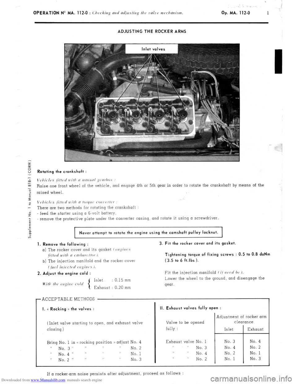
ADJUSTING THE ROCKER ARMS
Ir
E
2 Rotating the crankshaft :
7
m
Vc,birlvs /i//cd wifh n WRIINRI ~varbot :
E Raise one front wheel of the vehicle,
and engage 4th or 5th gear in order to rotate the crankshaft by means of the
3
6 raised wheel.
I
e Vchirlcs /ittcd wilh a lo~qnr covwrlc~ :
- There are two methods for rotating the crankshaft :
Gz feed the
starter using CI G-volt battery,
;
remove the protective plate under the converter casing, and rotate it using a screwdriver.
:
Never attempt to rotate the engine using the camshaft pulley locknut.
1. Remove the following :
a) The rocker cover and its gasket (~,ofii~rr~s
/i//d Will, a rarb,,wt/or I.
b) The injection manifold and the racker-cover
(/,,<,I iU/<~CfPd r,zgir,rs 1.
2. Adiust the engine cold :
Inkt : 0.15 mm
With lb<‘
3. Fit the rocker cover and its gasket.
Tightening torque of fixing screws : 0.5 to 0.8 daNm
(3.5 tc. 6 ft.lbs ).
Fit the injection manifold f i/ nczvd br 1.
Lower the wheel to the ground,
and disengage the
gear.
r ACCEPTABLEMETHODS
I I
I. (< Rocking )> the valves :
(Inlet valve starting to open, and exhaust valve
I
closing) closing)
Bring No. 1 in <, rocking position /) adjust No. 4 Bring No. 1 in <, rocking position /) adjust No. 4
II II
No. 3” ” ” ” No. 3” ” ” ” No. 2 No. 2
0 0
No.4 I’ ” ” ” No.4 I’ ” ” ” No. 1 No. 1
” No.2 ” ” ” ” ” No.2 ” ” ” ” No. 3 No. 3
II. Exhaust valves fully open :
Valve to be opened
fully : Adjustment of rocker arm
CleUKUlCe
Exhaust valve No. 1
,, I, No. 3
,, ,, No. 4
,, ,, No. 2
If a rocker-rim noise persists after adjustment, proceed as follows :
Page 71 of 394
Downloaded from www.Manualslib.com manuals search engine OPERATION No MA. 120.0 : Chrrki,,~ the /iminp. Op. MA. 120-O 1
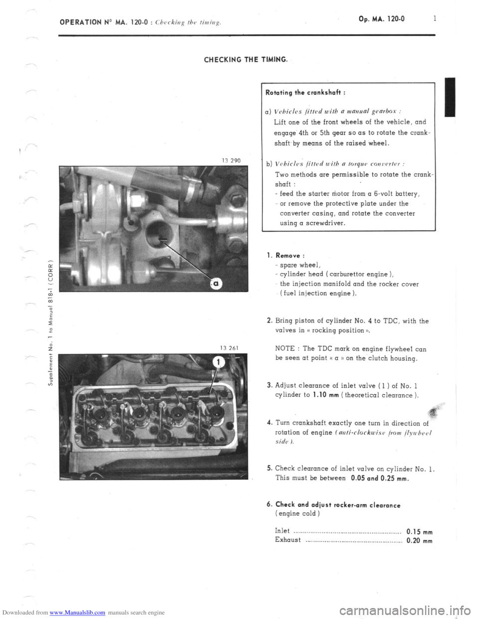
CHECKING THE TIMING.
lototing the crankshah :
) Vebirl~s /i/fed with a mantra~ gearbox :
Lift one of the front wheels of the vehicle, and
engage’ 4th or 5th gear so as to rotate the crank-
shaft,
by means of the raised wheel.
1) Vehicles /itted with n torqee ronrwrter :
Two methods are permissible to rotate the crank
shaft :
- feed the starter “iota from (I &volt battery,
or remove the protective plate under the
converter casing, and rotate the converter
using a screwdriver.
1. Remove :
spore wheel,
cylinder head (carburettor engine 1,
the injection manifold and the rocker cover
(fuel injection engine 1.
2. Bring piston of cylinder No. 4 to TDC. with the
valves in (( rocking position x
NOTE : The TDC mark on engine flywheel co”
be see” at point (( a )) on the clutch housing.
3. Adjust clearance of inlet valve ( 1 ) of No. 1
cylinder to
1.10 mm (theoretical clearance 1.
4. Turn crankshaft exactly one turn in direction of
rotation of engine f m/i-clockwise iro>t! /lyre hpel
side I.
5. Check clearance of inlet valve on cylinder No. 1.
This must be between 0.05
and 0.25 mm.
6. Check and adiust rocker-arm clearance
(engine cold )
Inlet .__....__.............................................,.,, 0.1 5 mm
Exhaust . . . . . . . . . . . . . . . . . . . . . . . . . . . . . . . . . . . . . . . . . . . . . . . . . . . . 0.20 mm
Page 152 of 394
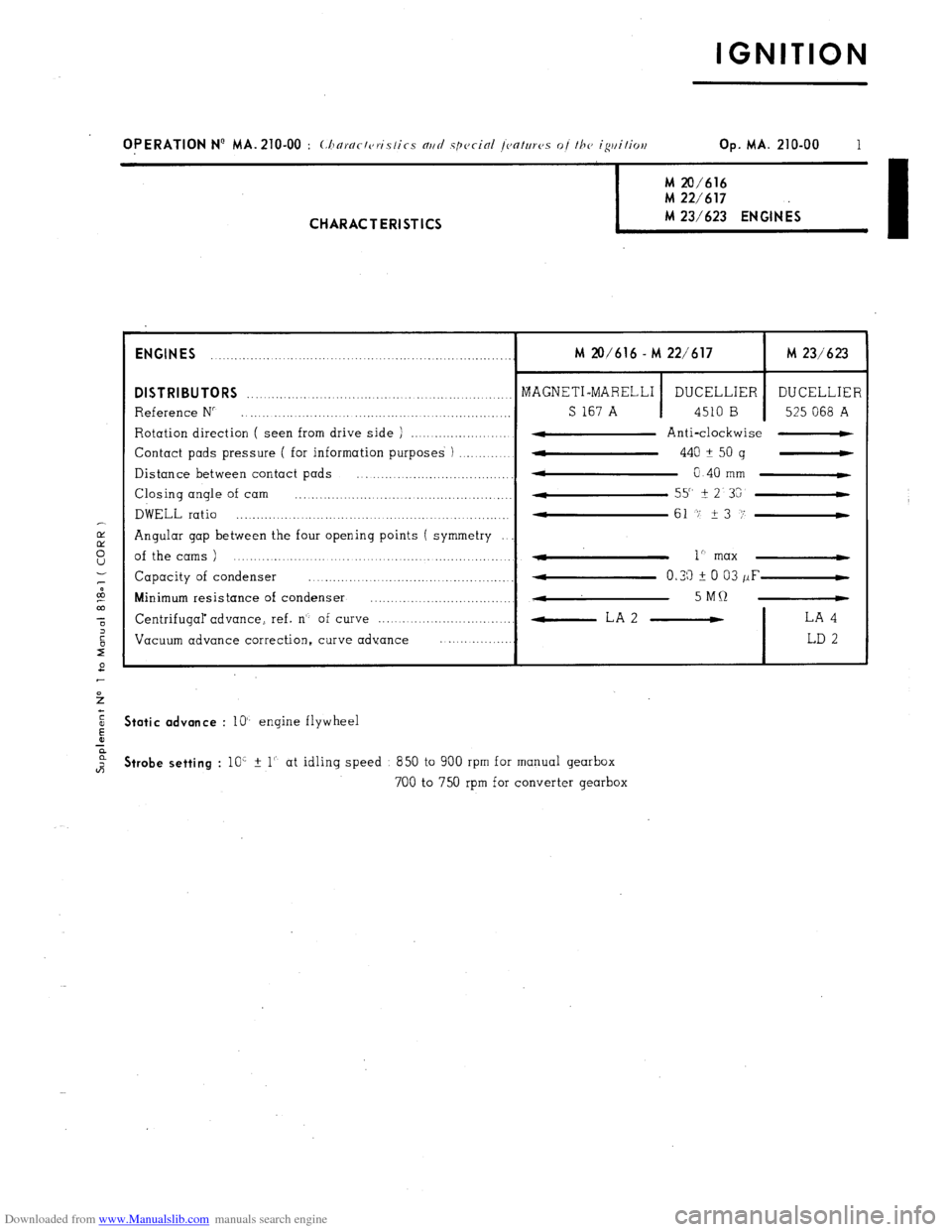
Downloaded from www.Manualslib.com manuals search engine IGNITION
OPERATION N’ MA. 210-00 : (:horr/r/c,ri.s/ics nrtrl spccinl /C,O/UTCJS of /he igtti/ioe Op. MA. 210-00 1 M 20/616
M 22/617 M 23/623 ENGINES
I CHARACTERISTICS
ENGINES
........ ........... ................................................. M 20/616 - M 22/617 M 23/623
DISTRIBUTORS ........................................... MAGNETI-MARELLI _._ ..............
DUCELLIER DUCELLIER
Reference N” ........................... .., ............................. _._ S 167 A 4510 B 525 068 A
Rotation direction ( seen from drive side ) ....................... 4 Anti-clockwise -
Contact pads pressure ( for information purposes ) ..............
w 440 A
50 g -
Distance between contact pads
* ................................... 0 40 mm C
Closing angle of cam ................... .................................. 55" It
2 3G
DWELL ratio ............................................... 4
....... .......... 61 -7 23 i’-
Angular gap between the four opening points ( symmetry
of the cams ) ....................................................... - 1” max 4
Capacity of condenser ......... ... ............... ...... ........ 4 0.33 i 0 03 /IF-
Minimum resistance of condenser ...............................
., ...
4 5MQ -
Centrifugal advance, ref. n’- of curve ................................. -LA2 - LA 4
Vacuum advance correction, curve advance ..................
LD 2 Static advance
: lo’- engine flywheel Strobe setting
: 10’ % 1’. at idling speed 850 to 900 rpm for manual gearbox
700 to 750 rpm for converter gearbox
Page 155 of 394
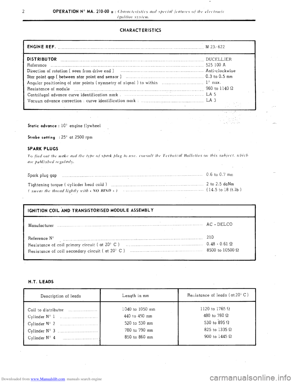
Downloaded from www.Manualslib.com manuals search engine CHARACTERISTICS
ENGINE REF.
........................................................................................... ........................ M 23/ 622
DISTRIBUTOR DUCELLIER ..................................................................................................................
Reference ..................................................................................................................... 525 100 A
Direction of rotation ( seen from drive end ) . .................................................................
Anti-clockwise
Star point gap ( between star point and sensor ) .............................................................. 0.3 to 0.5 mm
Angular positioning of star points ( symmetry of signal ) to within ........... ... ... ....... ..... 1” max.
Resistance of module 960 to 1140 fi .................................................................................................. Centrifugal
advance curve identification mark ................................. . ..................... LA 5
Vacuum advance correction
curve identification mark : ..................................................
LA 3 Static advance
: 10” engine flywheel . .’ Strobe setting
: 25’ at 2500 rpm SPARK PLUGS
Spark plug gap ................. ....
.................... ................... ....... 0.6 to 0.7 mm
......................... .........
Tightening torque ( cylinder head cold ) ....................................................................
2 to 2.5 daNm
( spl,(,c,)’ //T(, /hrc,nc/ /ig/T//>f cc,i//T H ,VO J~/,N/) )) ) ...................................................... (14.5 to 18 ft.lb )
I IGNITION COIL ‘AND TRANSISTORISED MODULE ASSEMBLY
I
Manufacturer ...............
................... ........ .............. .............. .......
AC - DELCO
...........................
Reference N” 210
....................................................... ...
....................................................
Resistance of coil primary circuit ( at 205 C ) ............................................................ 0.48 - 0.61 R
Resistance of coil secondary circuit ( at 20” C ) ......................................................... 8500 to 10500 fl H.T. LEADS
Description of leads Length in mm
Coil to distributor ....................... 1040 to 1050 mm
Cylinder N” 1 ............................ 440 to 450 mm
Cylinder N” 2 ............................. 520 to 530 mm
Cylinder N” 3 ................................ 780 to 790 mm
Cylinder No 4 850 to 860 mm
............................ Re:;istance of leads ( at 20L C )
I
1120 to 1765 (1
480 to 780 Q
530 to s95 Q
825 to 1335 Q
900 to 1445 R
Page 156 of 394
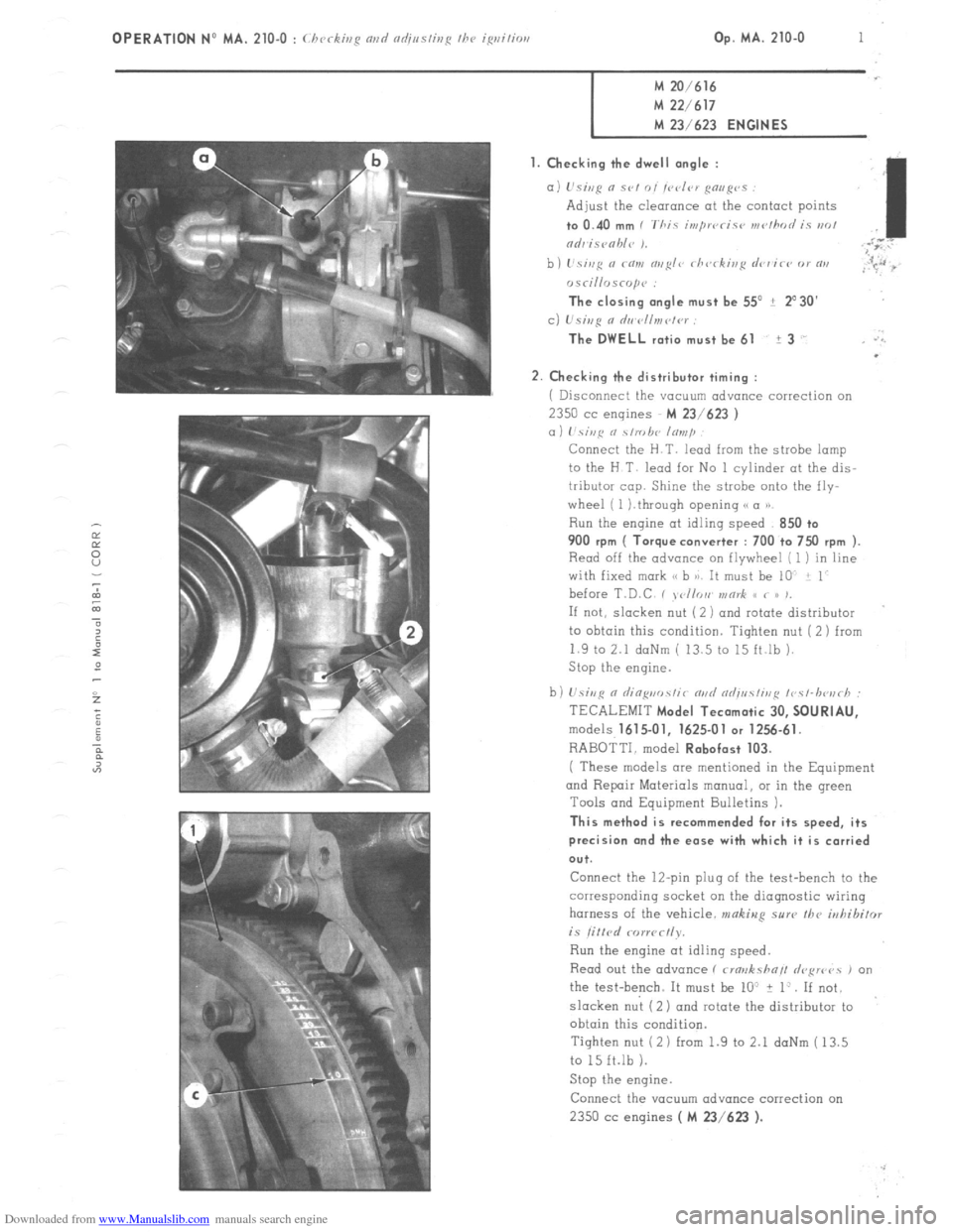
Downloaded from www.Manualslib.com manuals search engine OPERATION NO MA. 210-o : chcJckir,R fl,,d fld;linshp the, iRrlihil Op. MA. 210-O 1
M 20/616 M 22/617
M 23/623
ENGINES
1. Checking the dwell angle :
a) L’siep n SC,, 0, /C‘d‘,V gmg’s
Adjust the clearonce at the contact points to 0.40
mm I ‘Thic in,pwcic~~ wc,/hod iy PK,!
,I
ndr isvohle 1. ;i”
b) I’si,,fi a co,,, o,,~I<~ rh<,rkis~ drr’ir<, or RI,
,r 5.~~ :s
osri//risrop<~ :
The closing angle must be 55’ ? 2’30’
c) L’si,,g 0 d,,~r~ll,,,ct<~r :
The DWELL
ratio must be 61 i 3 .’ .‘.
.
2.
Checking the distributor timing :
i Disconnect the vacuum advance correction on 2350
cc engines M 23/623 )
a) hi,,c o \/robe lo,,,/~
Connect the H.T. lead from the strobe lamp
to the H T lead for No 1 cylinder at the dis-
tributor cop. Shine the strobe onto the fly-
wheel ( 1 ).through opening (( a P)
Run the engine at idling speed 850 +o 900
rpm ( Torque converter : 700 to 7x) rpm ).
Read off the advance on flywheel [ 1 ) in line
with fixed mark (< b 8). It must be 10 i 1
before T.D.C , , <,//or, v,or& S< < /> ,,
If not, slacken nut ( 2 ) and rotate distributor
to ohtoin this condition. Tighten nut (2) from
1.9 to 2.1 daNm ( 13.5 to 15 ft.lb ).
Stop the engine.
b) U.sivR n riin~uo.~~ir m,d od;uc!ir,,~ ~r~c~-lwu~h :
TECALEMIT
Model Tecamatic 30, SOURIAU,
models 1615.01, 1625-01 or 1256.61.
RABOTTI. model Robofast 103.
( These models are mentioned in the Equipment
and Repair Materials manual, OI in the green
Tools and Equipment Bulletins 1.
This method is recommended for its speed, its
precision and the ease with which it is carried
ou+.
Connect the 12-pin plug of the test-bench to the
corresponding socket on the diagnostic wiring
harness of the vehicle. makiug sure the
irrhibifor is litlrd rorwc~ly.
Run the engine at idling speed.
Read out the advance ( rma>rksha// drFwvs , on
the test-bench. It must be lo” + 1:. If not.
slacken nut (2) ond rotate the distributor to
obtain this condition.
Tighten nut (2 1 from 1.9 to 2.1 daNm ( 13.5
to 15 ft.lb 1.
Stop the engine.
Connect the YOCUU~ advance correction on 2350 cc
engines ( M 23/623 ).
Page 159 of 394
Downloaded from www.Manualslib.com manuals search engine 4 OPERATION No MA. 210-O : (hcrkir,p or,
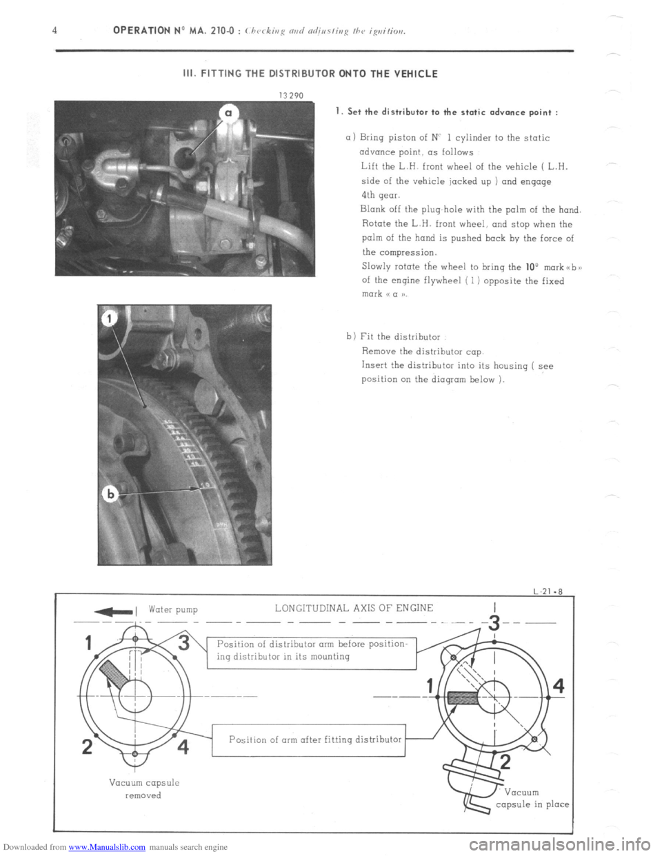
III. FITTING THE DISTRIBUTOR ONTO THE VEHICLE
1. Set the distributor to the static
advance point :
a 1 Bring piston of NC 1 cylinder to the static
advance point, as follows
Lift the L.H. front wheel of the vehicle ( L.H.
side of the vehicle jacked up ) and engage
4th gear.
Blank off the plug-hole with the palm of the hand.
Rotate the L.H. front wheel, and stop when the
palm of the hand is pushed back by the force of
the compression.
Slowly rotate the wheel to bring the 10”
morkabx
of the engine flywheel ( 1) opposite the fixed mark (c a aa.
b) Fit the distributor
Remove the distributor cap.
Insert the distributor into its housing ( see
position on the dioqram below 1.
-, water pump LONGITUDINAL AXIS OF ENGINE
--~-__ -- -- ----~--
Position of distributor arm before position-
ing distributor in its mounting
I
w
Vacuum capsule
removed
capsule in place Position of arm after fitting distributor
Page 161 of 394
Downloaded from www.Manualslib.com manuals search engine OPERATION No MA. 210-O a : C/ ‘CC ,r,,q rind ndj,,s/isp I/W ~~/<~c-/mr,ir ip,itior, 5?‘.5/‘.,11 k’ Op. MA. 210-O a 1
M 23/622 ENGINE
I. CHECKING THE IGNITION OM THE VEHICLE
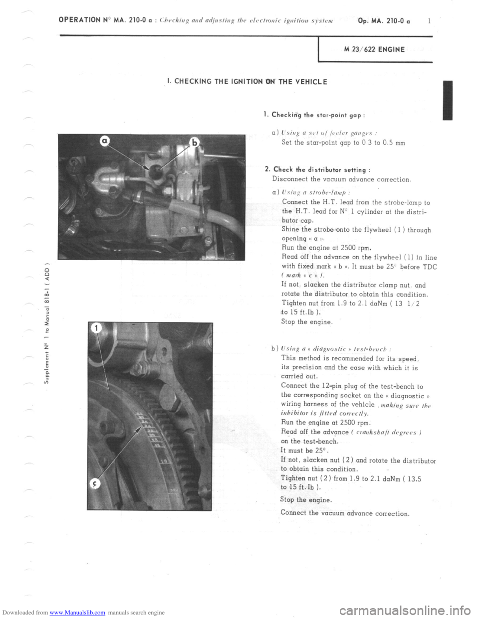
I. Checkin‘g the star-point gap :
a) L’si,,g N se, 0, /vdrr g”,,g”” :
Set the star-point gap to 0 3 to 0.5 mm
2. Check the distributor setting :
Disconnect the vacuum advance correction
a) L’sing 0 s/,uh‘4n,,,,p :
Connect the H.T. lead from the strobe-lamp to
the H.T. lead for N3 1 cylinder at the distri-
butor cap.
Shine the strobeonto the flywheel (1 1 through
opening e a 1).
Run the engine at 2500 rpm.
Read off the advance on the flywheel (1) in line
with fixed mark SC b )a. It must be 25’ before TDC
f mark x c x ).
If not. slacken the distributor clomp nut. and
rotate the distributor to obtain this condition.
Tighten nut from 1.9 to 2.1 doNm ( 13 1.12
to 15 ft.Ib ).
Stop the engine
b) Usisg n u rlia~,,ms/ir x /rs/.h<~,irh :
This method is recommended for its speed.
its precision and the ease with which it is
carried out.
Connect the 12-pin plug of the test-bench to
the corresponding socket on the G< diagnostic n
wiring harness of the vehicle n,aking sur(, ,h,
iuhihilor is /if/cd corr~~ctly.
Run the engine at 2500 rpm.
Read off the advance (
crawkshn// depws 1
on the test-bench.
It must be 25”.
If not, slacken nut (2 1 and rotate the distributor
to obtain this condition.
Tighten nut (2 1 from 1.9 to 2.1 daNm ( 13.5
to 15 ft.Ib ).
Stop the engine.
Connect the vacuum advance correction.
Page 164 of 394
Downloaded from www.Manualslib.com manuals search engine 4 OPERATION No MA. 210-O o : (./wrkh,i: rind nrlj,,s/inp /hc rlvr/,riai< igvi,io,, ~YS/C,,,,.
II;. FITTING THE DISTRIBUTOR ONTO THE VEHICLE
_ water pump
LONGITUDI 1 AL AXlS OF ENGINE
.-.-.-
distributor arm
Position of dist:ibutor arm befol
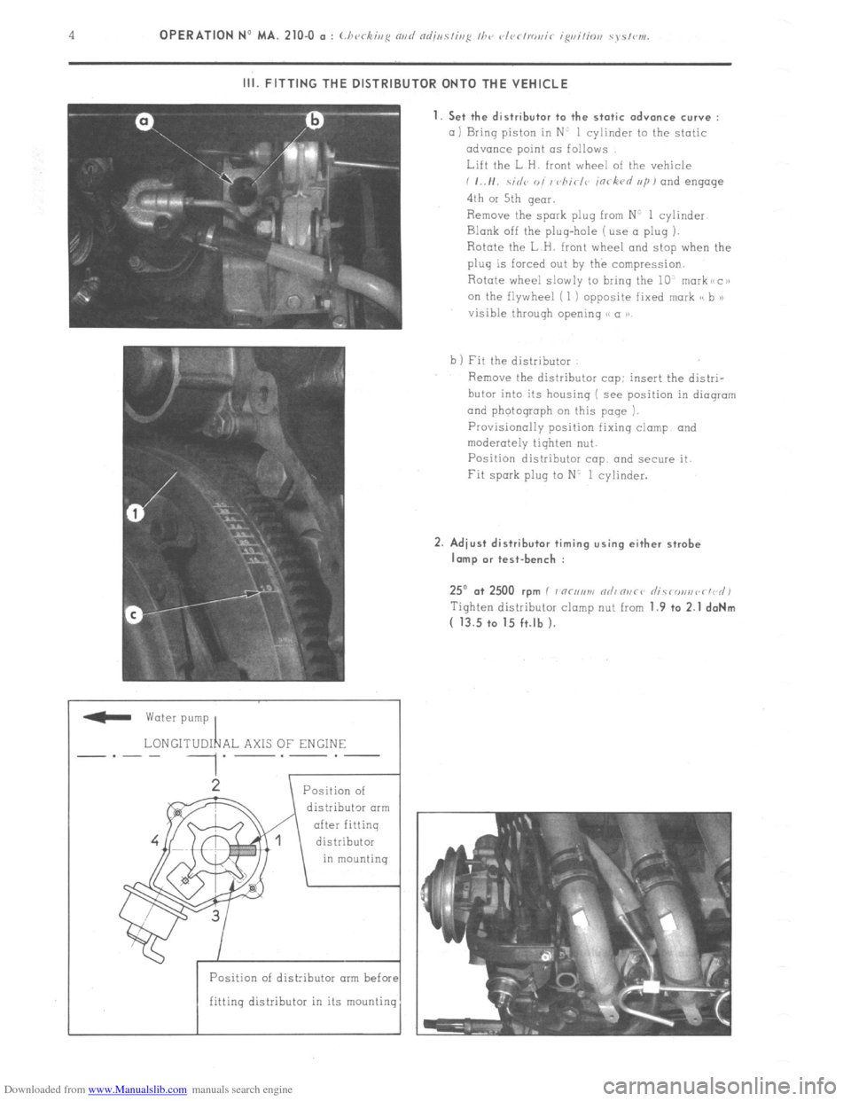
fitting distributor in its mountin 1. Set the distributor to the static advance curve :
a) Bring piston in N’ 1 cylinder to the static
advance point LTS follows
Lift the L H. front wheel of the vehicle
i ,..I,. .\;,I<~ o, / vhirl<~ in< kvd ,,/I, and engage
4th or 5th qeor.
Remove the spark plug from N’ 1 cylinder
Blank off the plug-hole (use a plug ).
Rotate the L H. front wheel and stop when the
plug is forced out by the compression.
Rotate wheel slowly to bring the 10, markiicai
on the flywheel ( 1 ) opposite fixed mark cs b >)
visible throuqh opening S< a ))
b 1 Fit the distributor
Remove the distributor cop: insert the distri-
butor into its housing ( see position in dioqrom
and photograph on this page ).
Provisionally position fixing clamp and
moderately tighten nut.
Position distributor cap and secure it.
Fit spark plug to N’ 1 cylinder. 2. Adiust distributor timing using either strobe
lamp or test-bench :
25” .a+ 2500 rpm I 7 “c,,,m nrli n,,ci’ rlicronsvr~d)
Tiqhten distributor clomp nut from 1.9 +o 2.1 daNm
( 13.5 to 15 ft.lb ).