wheel Citroen CX 1983 1.G Service Manual
[x] Cancel search | Manufacturer: CITROEN, Model Year: 1983, Model line: CX, Model: Citroen CX 1983 1.GPages: 394
Page 262 of 394
Downloaded from www.Manualslib.com manuals search engine STEERING COLUMN ( ‘11’ l’)‘o -1
L.44-21
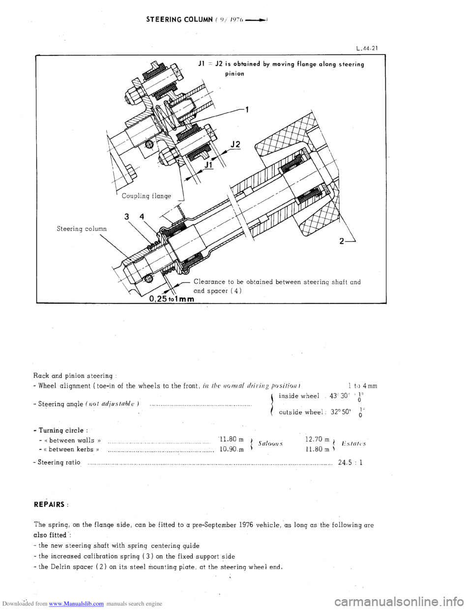
Jl = J2 is obtuined by moving flange along steering
pinion
Steering co1
Clearance to be obtained between steering shaft and
mind spacer (4)
1 a
Rack and pinion steering :
- Wheel alignment ( toe-in of the wheels to the front, i/z, /bc~ rtot~/nl rlrir,ir/g posifiort I 1 tk) 4 mm
inside wheel 43’30’
1”
- Steering angle (Ilot djustahlc~ ) 0
outside wheel : 32’50’ i’
- Turning circle :
- CC between walls )) Il.80 m
I Snloo~2 s 12.70 m
.
(! Estntc’s
- CC between kerbs )I
. . . . . ..__.._........................................,.,.. 10.90.m 11.80 m
- Steering ratio, .-.......................-............................................................................................................ 24.5 : 1
REPAIRS :
The spring, on the flange side, can be fitted to a preSeptember 1976 vehicle,‘as long as the following are
also fitted -:
- the new steering shaft with spring centerinq guide
- the increased calibration spring ( 3 ) on the fixed support side
- the Delrin spacer (2) on its steel mounting plate. at the steering wheel end.
Page 263 of 394
Downloaded from www.Manualslib.com manuals search engine ll, SPECIAL FEATURES
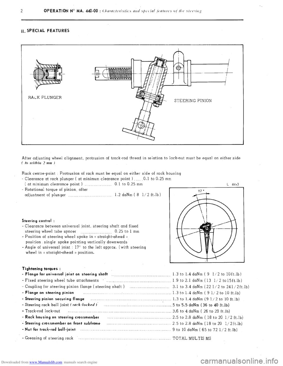
STEERING PINION
After adjusting wheel alignment, protrusion of track-rod thread in relation to lock-nut must be equal on either side
( .to within 2 mm )
Rack centre-point Protrusion of rack must be equal on either side of rack housing
- Clearance at rack plunger ( at minimum clearance point ) .O.l to 0.25
( at minimum clearance point ) ., .,...._...... .._._ 0 1 to 0.25 mm
- Rotational torque of pinion, after
adjustment of plunger .._..... .._.... 1.2 daNm ( 8 l/2 ft.lb)
L 44.3
Steering control :
- Clearance between universal joint, steering shaft and fixed
steering wheel tube spacer 0.25 to 1 mm
.._....__._..._.... ._..__..
- Position of steering wheel spoke in (( straight-ahead ))
position. single spoke pointing vertically downwards
- Angle of universal joint : 17” to the left approx. (with steering
wheel in (( straight-ahead )) position.
- Coupling for steering pinion flange ( steering shaft ) ....................................
- Flange on steering pinion ................................................................................
- Steering pinion securing flange ........................................................................
- Steering rack ball joint f rack Jacked )’ .............................................................
- Track-rod lock-nut ..............................................................................................
- Rack housing on steering crossmember ..........................................................
-. Steering crossmember on front subframe ..........................................................
- Nut for track-rod ball-joint ................. ................................... ..... ...................... Tightening torques :
- Flange for universal joint on steering shaft __..._.__.._._.........,.........................,. 1.3 to 1.4 daNm ( 9 11 2 to
lOft.lb)
- Fixed steering wheel tube attachments
. . . . . . . . . . . . . . . . . . . . . 1 9 to 2.1 daNm (13 l/2 to15ft.lb)
3.1 to 3.4 daNm (22 l/2 to 241/2ft,lb)
1.3 to 1.4 daNm ( 9 l/ 2 to 10 ft.lb)
1.3 to 1.4 daNm (9 l/2 to 10 ft.lb)
.5 to’5.5 daNm (36 to 40 ft.lb)
3.6 to 4 daNm ( 26 to 29 ft.lb)
2.5 to 2.8 daNm ( 18 to 20 l/2 ft.lb)
2.5 to 2.8 daNm (18 to 20 1/2ft.lb)
9 to 10 daNm ( 65 to 72 l/2 ft.lb)
- Greasing of steering rack TOTAL MULTIS MS
Page 264 of 394
Downloaded from www.Manualslib.com manuals search engine II. POWER STEERING WITH POWERED RETURN
I. CHARACTERISTICS
Hydraulically operated rack and pinion steering Steering
ratio . . . . . . . . . . . . . . . . . . . . . . . . . . . . . . . . . . . . . . . . . . . . . . . . . . . . . . . . . . . . . . . . . . . . . . . . . . . . . . . . . . . . . . . . . . . . . . . . . . . . . . . . . . . . . . . . . . . . . . . . .. 13 5 i
- No of steering wheel turns from lock to lock
. . . . . . . .._._.__................................................ 25
- Turning circle (( between walls ))
11 80m
(.S x00 OIlCi ( s .2x0 solooll.~
(( between kerbs )) 10 90 m t
/( between walls )) 12 70 m
I( between kerbs 1) 11 80 m t I’\/N/l’ N/id I’n~\lix”
- Wheel alignment ( toe-in of wheels to the front i (i/l //I( //r~rjj/rll c/r;/ ii/:: p, cilirJ/i 1 1 to 4 mm
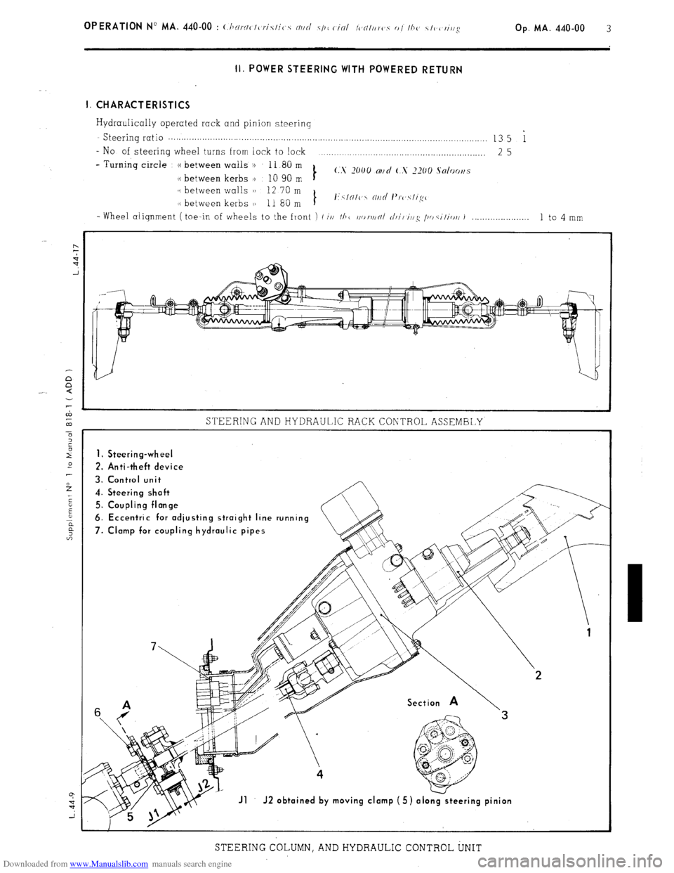
STEERING AND HYDRAULIC RACK CONTROL ASSEMBLY
1. Steering-wheel
2. Anti-theft device
3. Control unit
4. Steering shoft
5. Coupling flonge
6. Eccentric for odjusting stroight line running
7. Clomp for coupling hydraulic pipes
Jl J2 obtoined by moving clomp (5) olo
STEERING COLUMN, AND HYDRAULIC CONTROL UNIT
Page 266 of 394
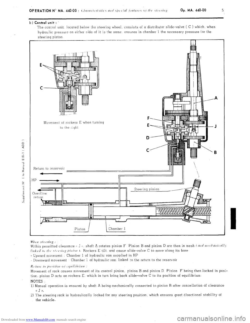
Downloaded from www.Manualslib.com manuals search engine b) Control unit : ’
The contra! unit located below the steering wheel, consists of a distributor slide-valve ( C ) which. when
hydraulic pressure on either side of it is the same ensures in chamber 1 the necessary pressure for the
steerinq piston
Movement of rockers E when turning
to the riqht
F
E
D
C
Return to reservoir
HP
QV re Wh <‘,I s I? cw%g .’
Within permitted clearance (1 J ):, shaft A rotates pinion F Pinion B and pinion D are then in mesh f NII~/ nl(,<.l1~)ji(nll>~
lillk cd lo II1 1’ ~/~~c,~i/lg /~ir/io/l 1. Rockers E tilt, and cause slide-valve C to move.along its bore
_ Upward movement : Chamber 1 of hydraulic ram supplied in HP
- Downward movement Chamber 1 of hydraulic ram linked to the return to the reservoir
lic,Inr~i lo fm.silio~i 0 I ~~yiiilihrif~vf
Movement of rack causes movement of its control pinion. pinion B and pinion D Pinion F being then locked in posi-
tion, pinion D acts on rockers E. which in turn brinq back slide-valve C to its position of equilibrium.
NOTES :
1) Manual operation is ensured by shaft A being mechanically connected to pinion B after cancellation of clearance
a J )).
2) The steering rack is hydraulically locked for any steering position, which ensures great directional stability of
the vehicle.
Page 269 of 394
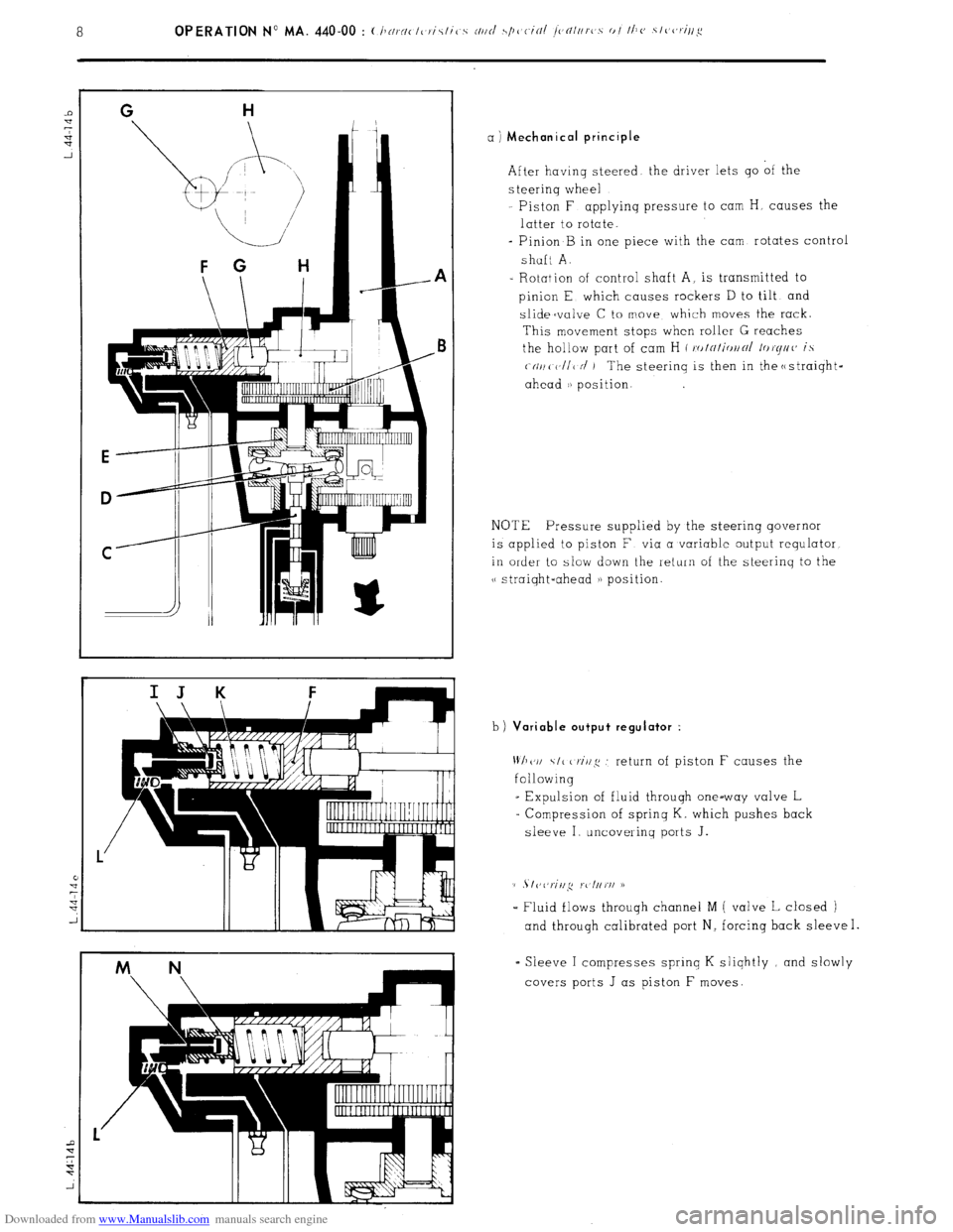
Downloaded from www.Manualslib.com manuals search engine a ) Mechanical principle
After having steered the driver lets go of the
s teerinq wheel
Piston F applyinq pressure to cam H, causes the
latter to rotate.
- Pinion B in one piece with the cam rotates control
shaft A.
- Rotation of control shaft A, is transmitted to
pinion E which causes rockers D to tilt and
slidecvalve C to move which moves the rack.
This movement stops when roller G reaches
the hollow part of cam H ( ro/~/i<,//~/ /or(//((’ is
(-(II/( V/I< N’ ) The steerinq is then in the c
NOTE Pressure supplied by the steering governor
is applied to piston F via a variable output requlator
in order to slow down the return of the steerinq to the
v straiqht-ahead a) position.
b)
Variable output regulator :
Wh(‘I/ \I< criq .’ return of piston F causes the
following
_ Expulsion of fluid through one-way valve L
= Compression of sprinq K. which pushes back
sleeve I uncovering ports J.
(1 . I vl,riil,q rc l//rI/ D
- Fluid flows throuqh channel M ( valve L closed )
and through calibrated port N, forcing back sleeve I.
= Sleeve I compresses sprinq K sliqhtly and slowly
covers ports J as piston F moves.
Page 272 of 394
Downloaded from www.Manualslib.com manuals search engine Op. MA. 440.00 11
2. SPECIAL FEATURES
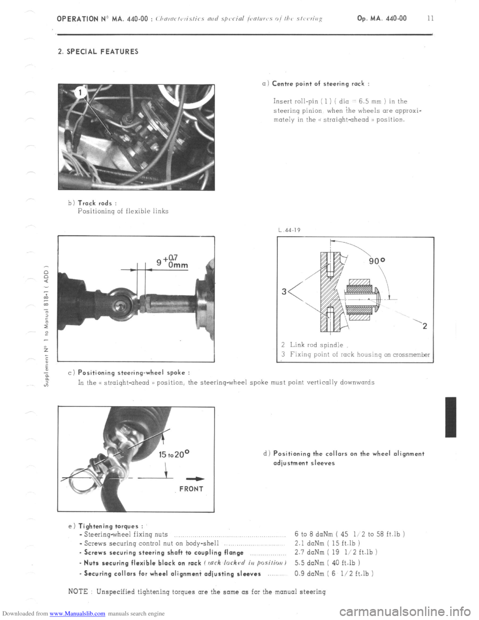
a) Centre point of steering rack :
Insert roll-pin ( 1 ) ( dio -: 6.5 mm ) in the
steering pinion when ihe wheels are appraxi-
mutely in the GG siroightohead )B position.
b 1 Track rods :
Positioning of flexible links
4J
a c) Positioning steering-wheel spoke :
2 Link rod spindle
3 Fixing point of rock housing on crossmemker
In the C( straight-ahead )) position, the steering-wheel spoke must point vertically
downwards
d) Positioning the collars on the wheel alignment
adjustment sleeves ---
FRONT
e) Tightening torques :
- Steering-wheel fixing nuts ..,.,........,......,.. .., 6 to 8 daNm ( 45 li 2 to 58 ft.lb j
- Screws securing control nut on body-shell 2.1 daNm ( 15 ft.lb )
. Screws securing steering shaft to coupling flange ,.,,.,,,,,.,.,.,,, 2.7 doNm ( 19 li2 ft.lb )
- Nuts securing flexible block on rack C rnrh lorkc~d iu psi/h) 5.5 doNm ( 40 ft.lb )
-Securing collars for wheel olignmani adjusting sleeves 0.9 daNm ( 6 l/2 ft.lb )
NOTE Unspecified tightening torques are the same as for the manual steering
Page 273 of 394
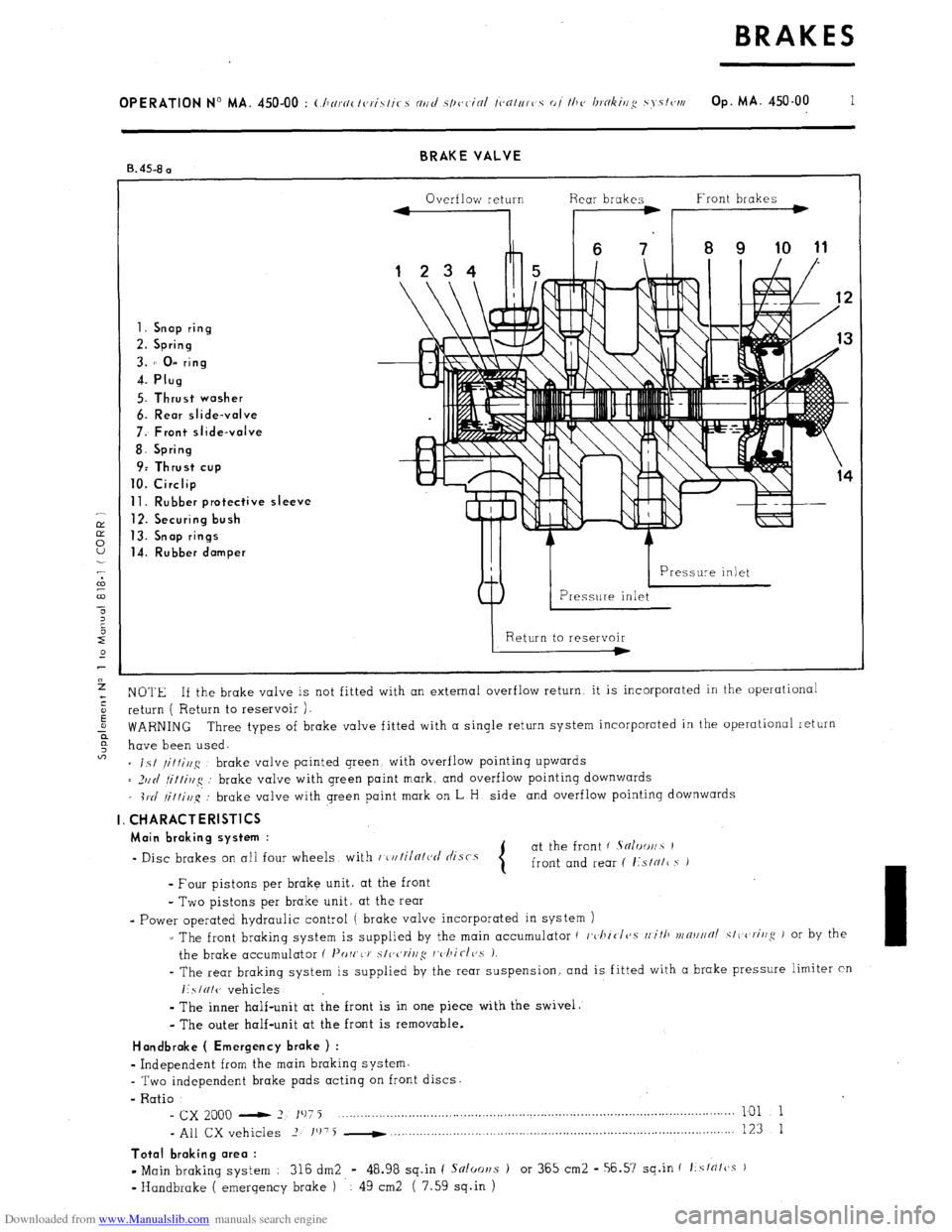
Downloaded from www.Manualslib.com manuals search engine BRAKE VALVE
B. 45-8 a
Overflow return Rear brakes Front brakes
1. Snap ring
2. Spring
3. 1’ 0” ring
4. Plug
5. Thrust washer
6. Rear slide-valve
7: Front slide-valve
8. Spring
9: Thrust cup
10. Circlip
11. Rubber protective sleeve
12. Securing bush
13. Snap rings
14. Rubber damper
NOTE If the brake valve is not fitted with an external overflow return, it is incorporated in the operational
return ( Return to reservoir ).
WARNING Three types of brake valve fitted with a single return system incorporated in the operational return
have been used.
= is/
/it/i//g brake valve painted green with overflow pointing upwards
= _)IIII
fi/tirlg : brake valve with green paint mark, and overflow pointing downwards
_ i1.d
/it/i,l~q’: brake valve with green paint mark on L H side and overflow pointing downwards
I. CHARACTERlSTlCS
Main braking system :
- Disc brakes on all four wheels with r~u/iln/ct/ tlisrs at the front ( Sn/oo//~ I
front and rear ( I:sIN/~ s i
- Four pistons per brake unit. at the front
- Two pistons per brake unit, at the rear
- Power operated hydraulic control ( brake valve incorporated in system )
z The front braking system is supplied by the main accumulator ( c,~l~icI~~.s
rli/ll vrn~l//~/ SIC criug J or by the
the brake accumulator ( I’orr,< J’
s/ccrivg rc,/~iclc,s 1.
- The rear braking system is supplied by the rear suspension. and is fitted with a brake pressure limiter cn
I:SIUI(J vehicles
-
The inner half-unit at the front is in one piece with the swivel.
- The outer half-unit at the front is removable.
Handbroke ( Emergency brake ) :
w
Independent from the main braking system.
- Two independent brake pads acting on front discs.
- Ratio
- cx 2000 - 2 197 j ___._....._..._..._.........,............................................................................... 101 1
- All CX vehicles 2 1’j75 -
. . . . . . 123 1
Total braking area :
- Main braking system : 316 dm2 - 48.98 sq.in ( Snloor~s ) or 365 cm2 - 56.57 sq.in f f:sfrffcss )
v
Handbrake ( emergency brake ) 49 cm2 ( 7.59 sq.in )
Page 282 of 394
Downloaded from www.Manualslib.com manuals search engine OPERATION No MA. 451-O : Uwckirrg the hrflkv rov,~o,rrnts Op. MA. 451.0 1
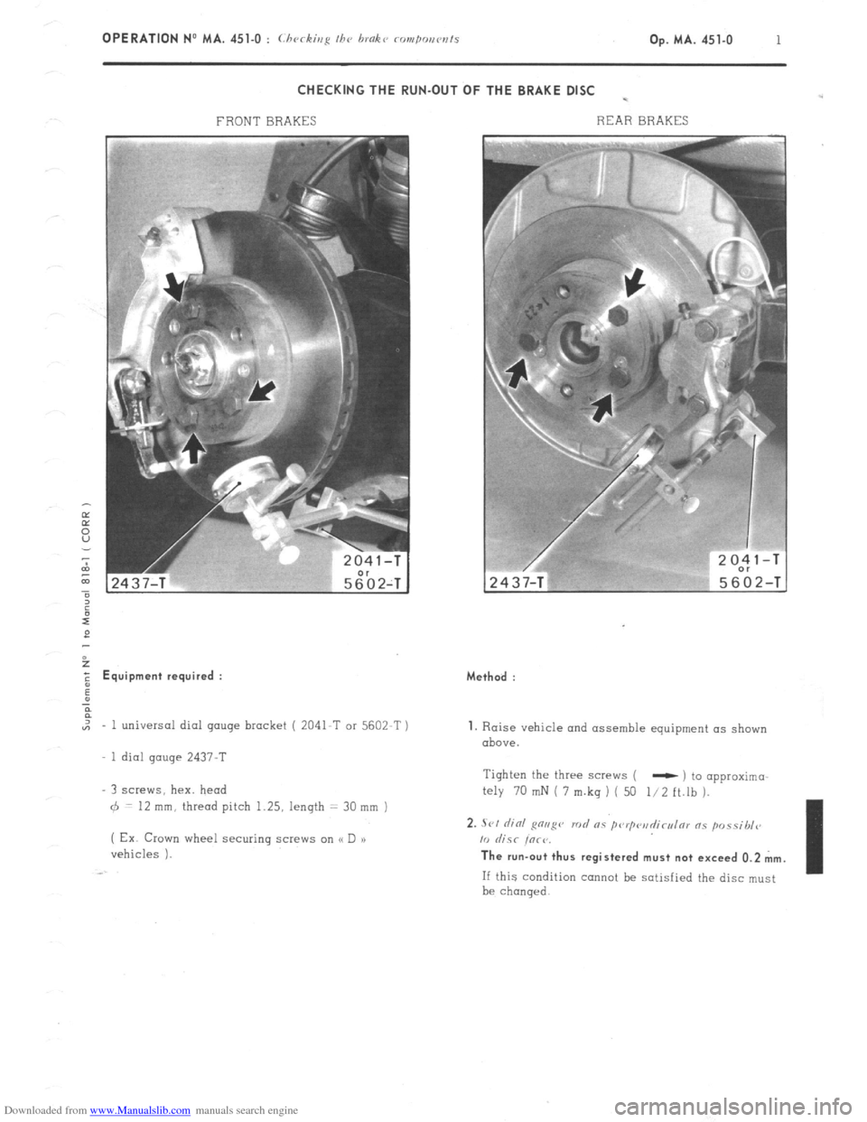
CHECKING THE RUN-OUT OF THE BRAKE DISC -
FRONT BRAKES REAR BRAKES 2
E Equipment required :
,,, - 1 universal dial gauge bracket ( 2041-T or 5602-T )
1 dial gauge 2437-T
3 screws, hex. head
6 = 12 mm, thread pitch 1.25, length = 30 mm )
( Ex Crown wheel securing screw on (< D a)
vehicles ). Method :
1. Raise vehicle and assemble equipment as shown
above.
Tighten the three screws (
- ) to opproximo
My 70 mN i 7 m.kq ) ( 50 l/2 ft.lh ).
2. .Sl,l did g”“g” rod RS pwp<‘il~cl,l171 ns p”ssibl<~
10 &SC iorr. The run-out thus registered must not exceed 0.2 mm.
If this condition cannot be satisfied the disc must
be chanqed.
Page 283 of 394
Downloaded from www.Manualslib.com manuals search engine Op. MA. 453-O 1
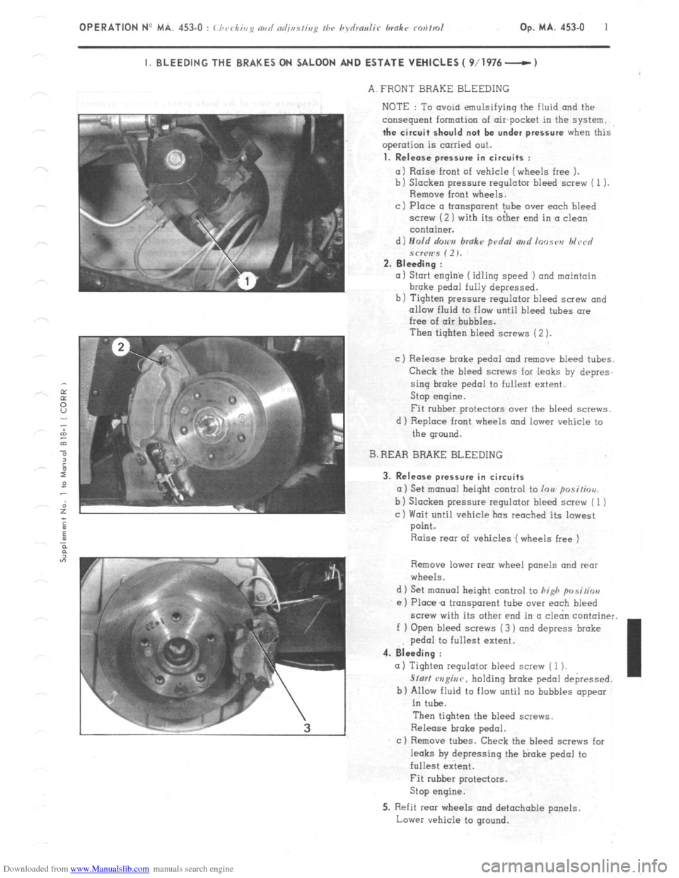
I. BLEEDING THE BRAKES ON SALOON AND ESTATE VEHICLES ( 9/1976- )
A. FRONT BRAKE BLEEDING
NOTE : To avoid emulsifying the fluid
and the
consequent formation of air-pocket in the system,
the circuit should not be under pressure when this
operation is carried out.
1. Release pressure in circuits :
a) Raise front of vehicle (wheels free 1.
b) Slacken pressure regulator bleed screw ( 1 ).
Remove front wheels.
c ) Place CI transparent tube over each bleed
screw (2 ) with its oiher end in CI clean
container.
d) Hold r/on,,,
brake pdnl ar,d loose,, blvcrl
*cr(Iws (2). 2. Bleeding :
(I 1 Start engin’e (idling speed 1 and maintain brake
pedal fully depressed.
b) Tighten pressure regulator bleed screw and
allow fluid to flow until bleed tubes ore
free of air bubbles.
Then tighten bleed screws (2 ).
c) Release broke pedal and remove bleed tubes.
Check the bleed screws for .leaks by depres-
sing brake pedal to fullest extent.
Stop engine.
Fit rubber protectors over the bleed screws.
d 1 Replace front wheels and lower vehicle to
the ground.
B. REAR BRAKE BLEEDING
3. Release pressure in circuits
a) Set monuol height control to lou posi/iou.
b 1 Slacken pressure regulator bleed screw ( 1 )
c) Wait until vehicle has reoched.its lowest
point.
Raise rear of vehicles (wheels free )
Remove lower rear wheel panels and rear
wheels.
d 1 Set manual height control to
hifih positior,
e ) Place Q transparent tube over each bleed
screw with its other end in (I cl&n container.
f ) Open bleed screws (3 ) and depress broke
pedal to fullest extent. 4. Bleeding :
(I) Tighten regulator bleed screw ( 1 1.
Slur/ w?@nr, holding broke pedal depressed.
b) Allow fluid to flow until no bubbles appear
in tube.
Then tighten the bleed screws.
Release brake pedal.
c ) Remove tubes. Check the bleed screws for
leaks by depressing the bloke pedal to
fullest extent. I
Fit rubber protectors.
Stop engine.
5. Refit rear wheels and detachable panels.
Lower vehicle to ground.
Page 284 of 394
Downloaded from www.Manualslib.com manuals search engine 2 OPERATION N” MA. 453-O : (./ ‘cc ,,,g md ndjaslisg I/w hsdrmlir hrnkr rev/m/
k.
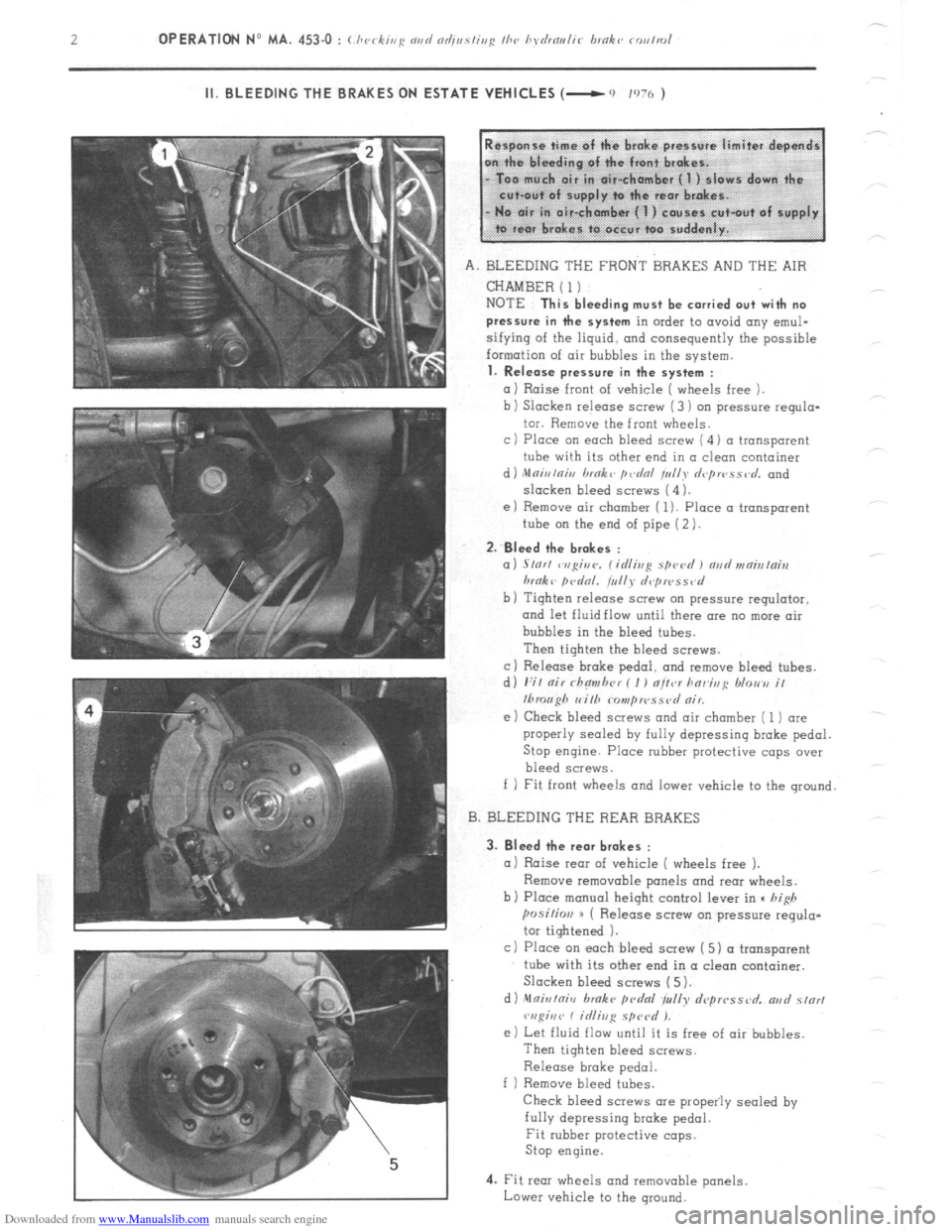
II. BLEEDING THE BRAKES ON ESTA ,TE VEHICLES (- 0 ,970 )
A. BLEEDING THE FRONT BRAKES AND THE AIR
CHAMBER ( 1)
NOTE
This bleeding must be carried out with no
pressure in the system
in order to avoid any emul-
sifying of the liquid. and consequently the possible
formation of air bubbles in the system.
1. Release pressure in the system :
a 1 Raise front of vehicle ( wheels free ).
b ) Slacken release screw (3 ) on $ressure requlo-
tor. Remove the front wheels.
c 1 Place on each bleed screw ( 4 1 a transparent
tube wi!h its other end in a clean container
d ) ,Mnir,lnh, brnk L p&d /u//y d<~pwss,~d. and
slacken bleed screws (4 ).
e) Remove air chamber ( 1). Place a transparent
tube on the end of pipe (2 ).
2.
Bleed the br.kes :
a) S/or/ ~v,gir,c,. C id/ivg spevd I md vrnialni,r
hrnk L firdnl. tullr d,~pwss<~d
b) Tighten release screw on pressure regulator.
and let fluid flow until there are no more air
bubbles in the bleed tubes.
Then tighten the bleed screws.
c) Release broke pedo1, and remove bleed tubes.
d) I:;/ nir rhnmhrr ( I ) nltcr hnr~htg /dorm i/
Ibrouph I, i/h Nmp IPSS ?,I nir.
e ) Check bleed screws and air chamber ( 1) are
properly sealed
by fully depressing brake pedal.
Stop engine. Place rubber protective caps over
bleed screws.
f 1 Fit front wheels and lower vehicle to the ground
B. BLEEDING THE REAR BRAKES
3.
Bleed the rear brakes :
a 1 Raise rear of vehicle ( wheels free ).
Remove removable panels and rear wheels.
b) Place manual height control lever in c high
posi~im H ( Release screw on pressure regula-
tor tightened 1.
c) Place on each bleed screw ( 5) a transparent
tube with its other end in a clean container.
Slacken bleed screws (5).
d) nlfliuiniv broke pcdfll ~yrrlly depwssvd. ar,d s/or,
vspiuv C idiivg sprcd ).
e) Let fluid flow until it is free of air bubbles.
Then tighten bleed screws.
Release brake pedal.
f ) Remove bleed tubes.
Check bleed screws are propeily sealed by
fully depressing broke pedal.
Fit rubber protective cops.
Stop engine.
4. Fit rear wheels and removable panels
Lower vehicle to the ground.