wheel Citroen CX 1983 1.G Owner's Manual
[x] Cancel search | Manufacturer: CITROEN, Model Year: 1983, Model line: CX, Model: Citroen CX 1983 1.GPages: 394
Page 165 of 394
Downloaded from www.Manualslib.com manuals search engine OPERATION No MA. 220-O : (.hrrkinfi Ih e oil pr~ssrrrc m the rehicle Op. MA. 220.0 1
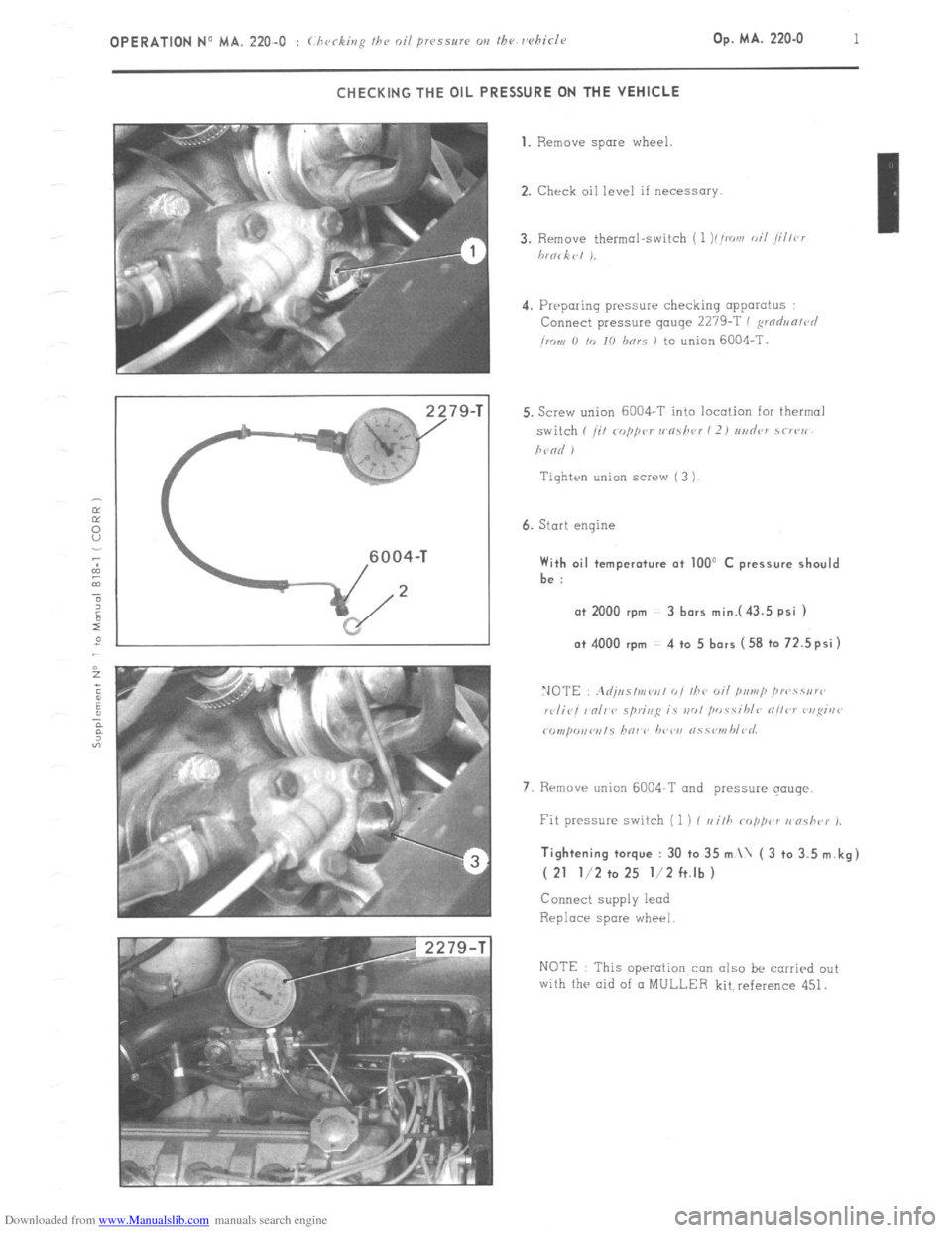
CHECKING THE OIL PRESSURE ON THE VEHICLE
79-T 1. Remove spare
wheel.
2. Check oil level if necessary.
4. Preparing pressure checking apparatus
Connect pressure gauge 2279-T ( ,wdun/r~l
imn 0 /o IO hnrs 1 to union 6004-T.
Tiqhten union screw ( 3 )
6. Start engine With oil temperature at 100’ C pressure should
be :
a+ 2000 rpm 3 bars mini43.5 psi ) o+ 4000 rpm 4 to 5 bars (58 to 72.5psi)
7. Rrmave union 6004-T and pressure qouqe. Tightening torque : 30 to 35 m \ ( 3 to 3.5 m.kg)
( 21 l/2 to 25 l/2 ft.lb )
Connect supply lead
Replace spare wheel
NOTE This operation con also be carried out
with the aid of CI MULLER kit,reference 451.
Page 178 of 394
Downloaded from www.Manualslib.com manuals search engine OPERATION No MA. 230.0 : M k
08 ,ri,y r,i, //I<’ roo/i,ip c, s,w,,.
Op. MA. 230.0 1 FILLING THE WATER SYSTEM
IMPORTANT
: Core must be token to protect alternator from water whenever working on cooling systems fitted close to this unit.
Two operations are involved
- Complete filling i roolir~g c~s~<,v, nvd bvolvr ,,ail ,
- Partial filling I roolir,p ~J~S/IW, oul~* 1
NOTES
Draining the radiator and the engine unit does not involve draining the heater unit.
- De-aeration of the system is only operative when the thermostat is open 1 v,rgiur wnnu J.
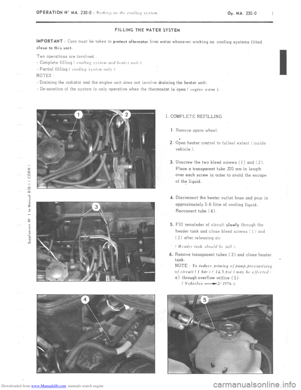
I. COMPLETE REFILLING 1. Remove
spare wheel
.
2. Open heater control to fullest extent ( inside
vehicle 1.
3. Unscrew the two bleed screws ( 1 ) and ( 2 ).
Place a tronsporent tube
200 mm in length
over each screw in order to ovoid the escape
of the liquid.
4. Disconnect the heater outlet hose and pour in
approximately 0.6 litre of cooling liquid.
Reconnect tube ( 4).
5. Fill remainder of circuit slowly through the
header tank and close bleed screws I 1) and
( 2) after releasing air
6. Remove transparent tubes ( 3) and close header
tank.
NOTE : To induce primitzg o/pum~,~~~sseri;irrp
o/ circuit I I bar 1 f 14. 5 psi ) may b+ r~i/vrtd:
(11 through overflow orifice ( 5)
I Vehicles -2/ 1976 ).
Page 179 of 394
Downloaded from www.Manualslib.com manuals search engine 2 OPERATION No MA. 230-O : II .h’ 0, fug Ol, I/7‘, rodir,p sys/w1.
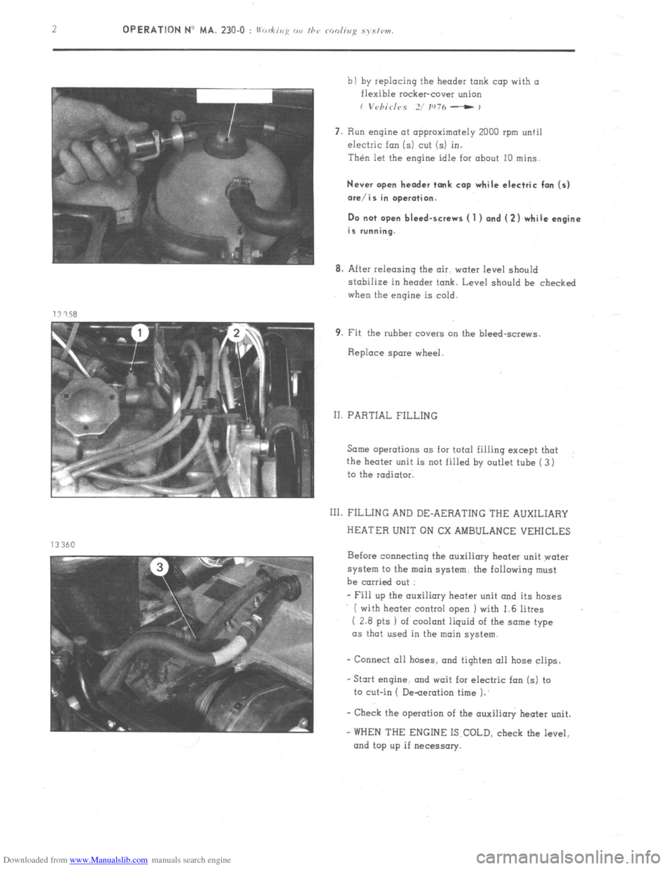
b) by replacing the header tank cap with a
flexible rocker-cover union
I V~~/7id<~S 2/ IU7h - ,
7. Run engine at approximately 2000 rpm until
electric fan (5) cut (5) in.
Then let the engine idle for about 10 mins.
Never open header tank cap while electric fan (5)
ore/is in operation.
Do not open bleed-screws ( 1 ) and (2) while engine
is running.
8. After releasing the air. water level should
stabilize in header tank. Level should be checked
when the engine is cold.
9. Fit the rubber covers cm the bleed-screws.
Replace spare wheel.
II. PARTIAL FILLING
Same operations as for total filling except that
the heater unit is not filled by outlet tube ( 3)
to the radiator.
111. FILLING AND DE-AERATING THE AUXILIARY
HEATER UNIT ON CX AMBULANCE VEHICLES
Before connecting the auxiliary heater unit water
system to the main system. the following must
be carried out :
- Fill up the auxiliary heater unit and its hoses
( with heater control open I with 1.6 litres
( 2.8 pts 1 of coolant liquid of the some type
as that used in the main
system.
- Connect all hoses. and tiqhten 011 hose clips.
-Stat engine. and wait for electric fan (5) to
to cut-in ( De-aeration time 1.’
- Check the operation of the auxilioly heater unit.
- WHEN THE ENGINE IS COLD, check the level,
and top up if necessary.
Page 201 of 394
Downloaded from www.Manualslib.com manuals search engine 12 OPERATION NP MA. 330.00 : (haro? gvmhr,, III. DRAINING AND REFILLING THE GEARBOX AND THE CONVERTER
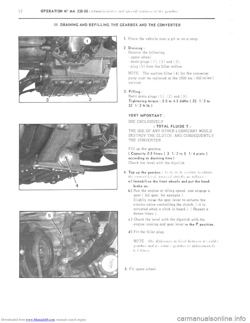
1. Place the vehicle over a pit 01 on a ramp
2. Draining :
Remove the following
spare wheel
drain plugs ( I), ( 2 I and i 3 ),
plug ( 5) from the filler orifice
NOTE The suction filter ( 4) for the converter
pump must be replaced at the 1000 km ( 60C miles j
service.
3. Filling :
Refit drain plugs ( 1). (2 1 and ( 3 1.
Tightening torque : 3.5 to 4.5 daNm ( 25 l/2 to
32 l/2 ft.lb )
VERY IMPORTANT :
USE EXCLUSIVELY
(< TOTAL FLUIDE T o
THEUSEOFANYOTHERLUBRICANTWOULD
DESTROY THE CLUTCH, AND CONSEQUENTLY
THE CONVERTER
Fill up the gearbox
( Co$acity 2-3 litres ( 3 l/2 to 5 l/4 pints )
according to draining time)
Check the level with the dipstick
4. Top up the gearbox :
> nc I<, b<’ r<,r/niii 10 <,hini,,
I/><,
broke on.
b) Run the engine at idlinq speed, and engage 01
gear ( 3rd gear, for example )
Slightly move the gear lever to actuate the
electro .valve controlling the clutch, ( it is
actuated when a click is heard ). ( Repeat a
dozen times ).
c) Check the level with the dipstick with the
enqine running and gear lever in the P position.
d) Fit the filler plug.
5. Fit spore wheel
Page 208 of 394

Downloaded from www.Manualslib.com manuals search engine DRIVE SHAFTS
OPERATION No MA. 372-00 : Cbaractcristics and sp
I
E 0
U RIGHT-HAND-DRIVE SHAFT
L. 37-2
1 S ft.lb 1 65 ft.lb
1 I; CHARACTERISTICS
- 1 co,nstant velocity ball-joint at wheel end
i 1 tri-axe joint at gearbox end Y = 423 mm ( 4-q gearbox )
Y = 388 mm ( 5-sp. gearbox ) II. SPECIAL FEATURES
Lubrication :
--TOTAL MULTIS MS grease
Page 233 of 394
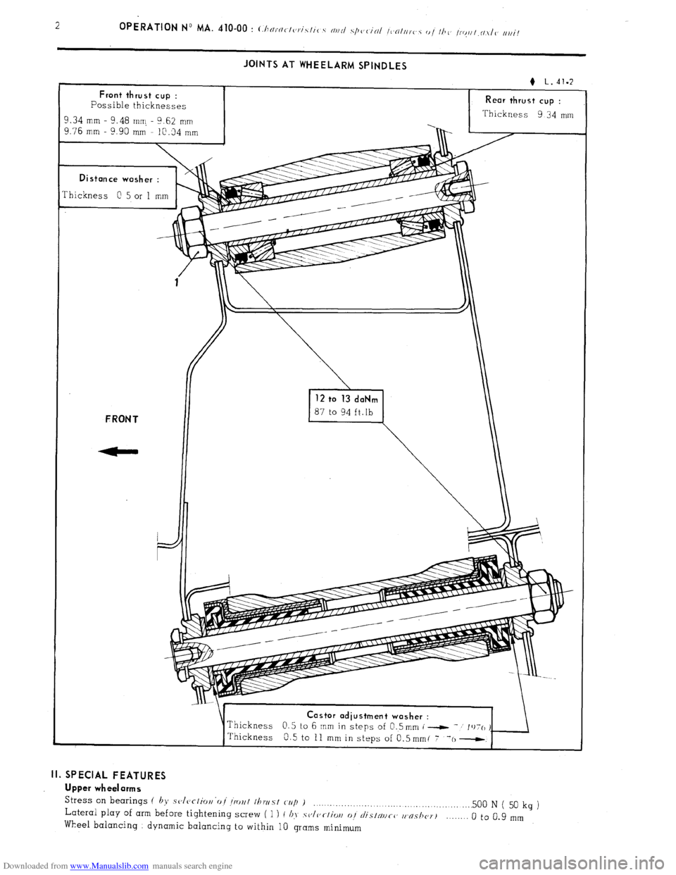
Downloaded from www.Manualslib.com manuals search engine JOINTS AT WHEELARM SPINDLES
Rear thrust cup :
Thickness 9 34 mm
Thickness
0 5 or 1 mm astor adiustment washer :
II. SPECIAL FEATURES
Upper wheelarms
Stress
on bearings ( by sclcrlior~‘oi Iro~l Ihwst cup ) _....._._........._... . . . . .._.............. .._..... 500 N ( 50 Lateral play of arm before tightening screw ( 1 ) I b>, .sv/c,c~/iw 01 ~~I/‘SINIICC, w~s/I~~T~ kg
)
Wheel balancing dynamic balancing to within 10 grams minimum _._..._. 0 to 0.9 mm
Page 234 of 394
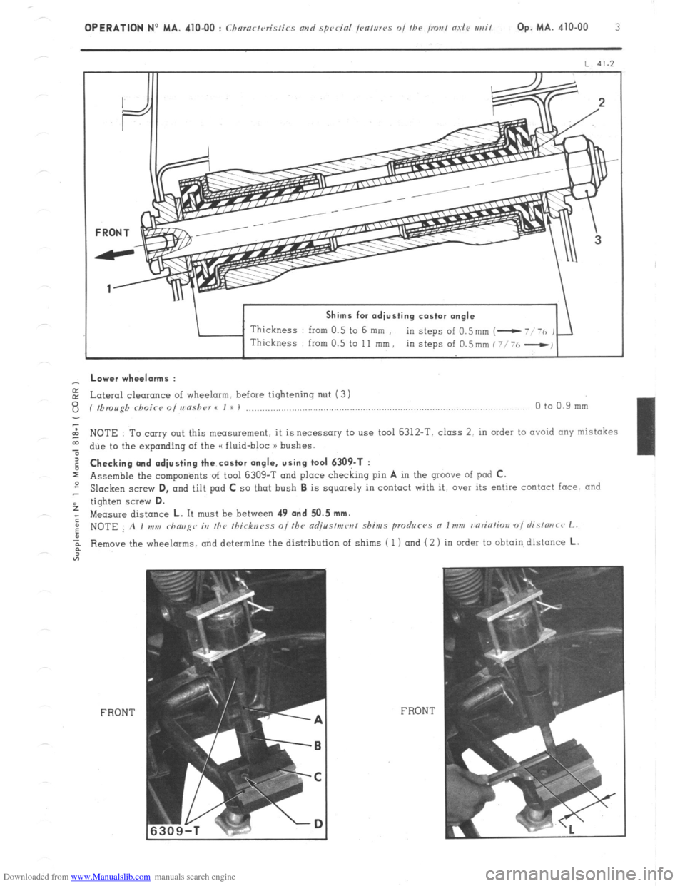
Downloaded from www.Manualslib.com manuals search engine Shims for adjusting castor angle
Thickness from 0.5 to 6 mm ,
in steps of 0.5mm (- - Lower wheelorms :
E Lateral cleoronce of wheelarm. before tightening nut (3 1
z ( fbmugh rhoicr o/ wnshr~r I I u I ,..................,.,............................,..,..,.,........................,....,...... 0 to 0.9 mm
2 NOTE To carry out this measurement, it is necessary to use tool 6312-T. class 2. in order to ovoid any mistakes
t due to the expanding of the G fluid-bloc n bushes. g Checking and adjusting the castor angle, using tool 6309-T :
s Assemble the components of tool 6309-T and place checking pin A in the groove of pod C.
2 Slacken screw D,
and tilt pad C so that bush B is squarely in contact with it, over its entire contact face. and
f tighten screw D.
; Measure distance L. It must be between 49 and 50.5 mm.
: NOTE A I mm rhaug~~ ia the Ihirknrss o//he adjr~s/mw/ shims produc-~s a Imm r~ariatim oi rlislmc~ L.
Remove the wheelarms, and determine the distribution of shims ( 1) and ( 2 ) in order to obtain distance L.
FRONT FRON T
Page 235 of 394
Downloaded from www.Manualslib.com manuals search engine 4 OPERATION No MA. 410-00 : (haractvristirs avd special jmtms oi the irout aslc urrit REPAIRS :
- Old type (( fluid-bloc )) bushes ( length : 79.5 mm ) must not be fitted with the later wheelarms.. and vice-versa.
- It is possible, on any vehicle, to fit one, or both sides with the later wheelarms, providing the appropriate shims
are used.
Page 236 of 394
Downloaded from www.Manualslib.com manuals search engine OPERATION No MA. 410-O : ( /,c
1
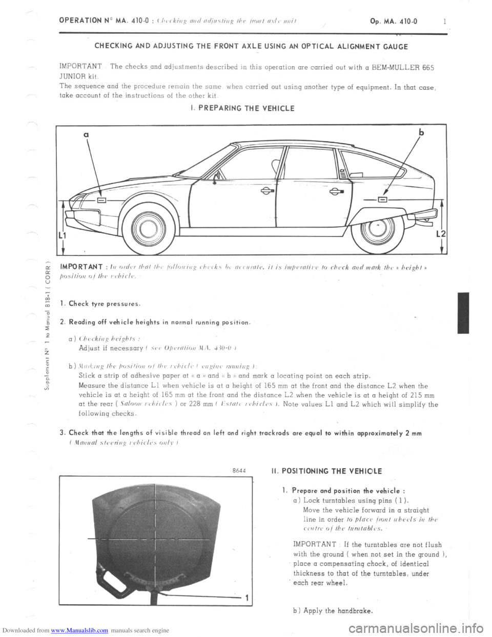
CHECKING AND ADJUSTING THE FRONT AXLE USING AN OPTICAL ALIGNMENT GAUGE
IMPORTANT The checks and adjustments described in this operation are carried out with a BEM-MULLER 665
JUNIOR kit
The sequence and
the procedure remain the same when carried out using another type of equipment. In that case,
take account of the instructions of the other kit I. PREPARING THE VEHICLE
cl
b
-.
I t 1. Check tyre pressures.
2. Rending off vehicle heights in normal running position
c,)
b ) .\I ri,f,,,g /he ,w.s;‘;o,,
Measure the distance Ll when vehicle is at II height of 165 mm at the front and the distance L2 when the
vehicle is at CL height of 165 mm at the front and the distance L2 when the vehicle is at a height of 215 mm
at the rear ( .Snloo,, I vhi~/r,s 1 or 228 mm I I:.s/o/c / chirlr,. 1. Note values Ll and L2 which will simplify the
following checks. 3. Check that the lengths of visible thread on left and right trackrods are equal to within approximately 2 mm
r .Mm,,tnl 51<,<,r;r,,q I <,hirl?s WI). )
r
Rh‘td Ii. POSITIONING THE VEHIOLE
7
-1 1. Prepare and position the vehicle :
a) Lock turntables using pins ( 1 ).
Move the vehicle forward in a straight
line in order 10 plnce ironl r,hccls iv
Ihe
rwrtw o/’ fhC /,,n,tab/~s.
IMPORTANT If the turntables ore not flush
with the ground ( when not set in the ground ),
place a compensating chock, of identical
thickness to that of the turntables, under
each rear wheel.
b 1 Apply the hondbrake.
Page 239 of 394
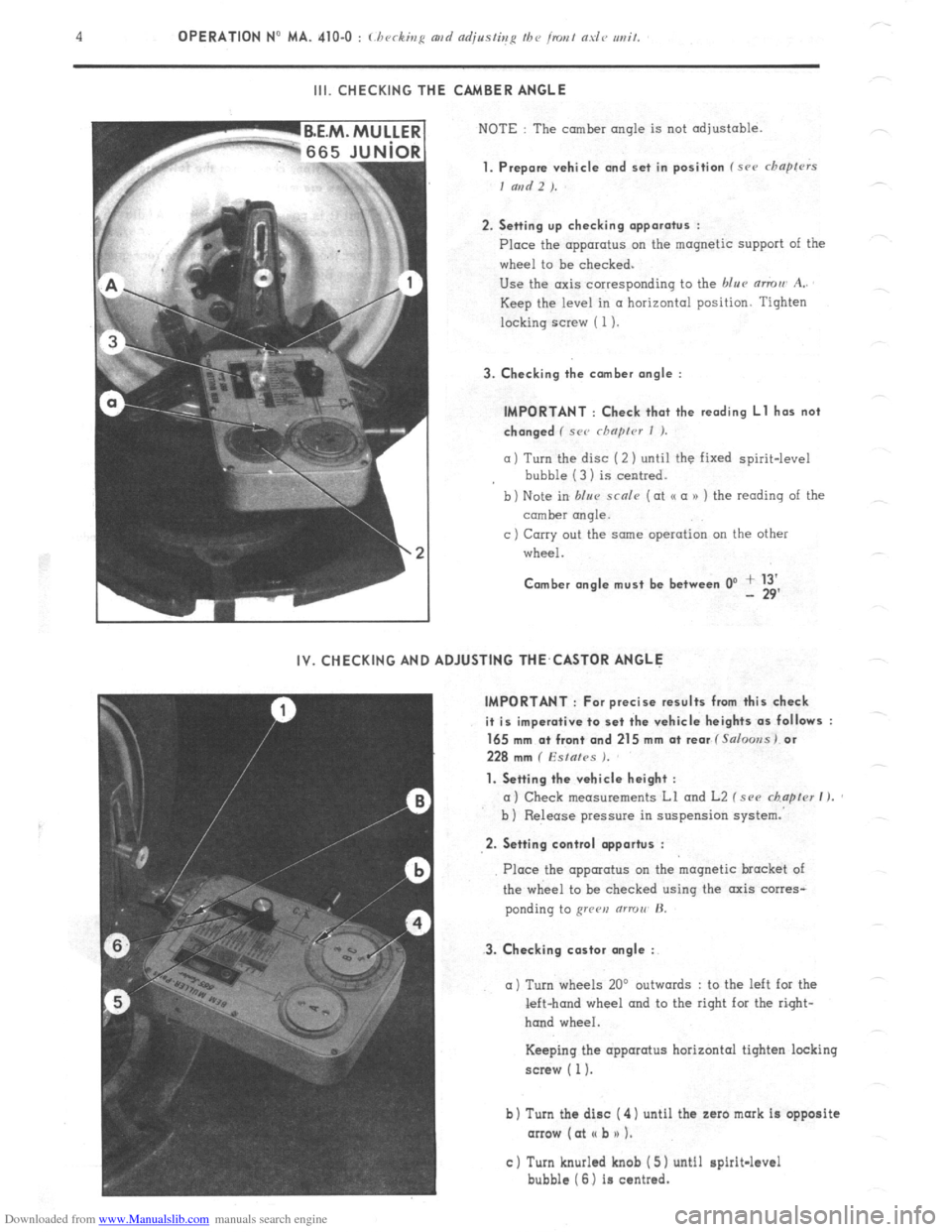
Downloaded from www.Manualslib.com manuals search engine III. CHECKING THE CAMBER ANGLE
NOTE : The camber angle is not adjustable.
1. Prepare vehicle and set in position f src chapfrrs
I and 2 ).
2. Setting up checking apparatus :
Place the apparatus on the magnetic support of the
wheel to be checked.
Use the axis corresponding to the blue mmu A..
Keep the level in a horizontal position. Tighten
locking screw ( 1).
3. Checking the comber angle :
IMPORTANT : Check that the reading Ll has not
changed ( SC<’ rhnprcr I ).
a) Turn the disc (2 ) until the fixed spirit-level
bubble (3 1 is centred.
b) Note in blur scnle (at o a n ) the reading of the
comber rmqle.
c ) Carry out the same operation on the other
wheel.
Comber angle must be between 0’ + 13’ - 29’
IV. CHECKING AND ADJUSTING THE,CASTOR ANGLE
IMPORTANT : For precise results from this check
it is imperative to set the vehicle heights as follows :
165 mm a+ front and 215 mm at rear f Salooss) or
228 mm ( Esfafes ).
1. Setting the vehicle height :
a) Check measurements Ll and L2 f see chapter I ).
b ) Release pressure in suspension system.
2. Setting control opportus :
3. Checking castor angle :
Place the apparatus on the magnetic bracket of
the wheel to be checked using the axis corres-
ponding to grren (ITTOII’ H.
a) Turn wheels 20’ outwards : to the left for the
left-hand wheel and to the right for the right-
hand wheel.
Keeping the apparatus horizontal tighten locking
screw ( 1).
b) Turn the disc ( 4) until the zaro mark is opposite
arrow (at I( b n 1.
c) Turn knurled knob ( 5) until spirit-level
bubble (6) is centred.