Temperature Citroen CX 1984 1.G Workshop Manual
[x] Cancel search | Manufacturer: CITROEN, Model Year: 1984, Model line: CX, Model: Citroen CX 1984 1.GPages: 394
Page 45 of 394
Downloaded from www.Manualslib.com manuals search engine 4 II - REPAIRS PLASTIC TUBING.
OBSERVATIONS :
a) This operation can be sarried out by sleeving the damaged tube
b) If two sleeves are to be located on one length of tube the interval between them must be about 30 in in order
to retain the flexibility of the tubing.
c) Obtain a bottle of Rilsan adhesive ( 125 cc ) sold by the BOYRIVEN firm , 37 bis rue de Villiers _
92200 u NEUILLY sur SEINE - Tel. 624-36-11
( Rilsan adhesive harms the skin : avoid touching it with the fingers, use a wooden spatula instead
1. Cut the tubing and roughen the ends over a lenqth of some 3.5 in. with abrasive paper N” 600
2. Carefully deqrease the roughened ends and the sleeve with trichlorethylene
3. Heat the Rilsan adhesive in a water-bath to raise its temperature to 60°C.
Do root c~sc-c~c~d /his Icv~p~~rntriw.
NOTE : This operation is essential to cut down drying time
4, Coat the ends of the tube and the inside of the sleeve with adhesive.
Leave the parts to dry for a few minutes.
Insert the ends of the tube into the sleeve.
).
Allow the assembly to dry for three to four hours before using the repaired tube aqain.
Page 49 of 394
Downloaded from www.Manualslib.com manuals search engine Op. MA. 03 3
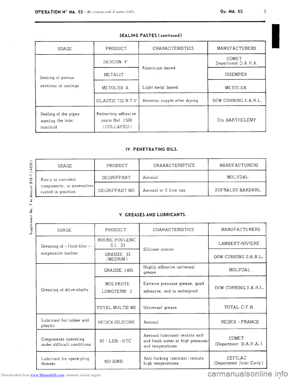
SEALING PASTES (continued)
USAGE
Sealing of porous
sections of casings
Sealing of the pipes
warning the inlet
manifold PRODUCT CHARACTERISTICS MANUFACTURERS
COMET
DEVCON F
Department D.A.V.A.
Aluminium based
METALIT DISEMPEX
METOLUX A Light metal based
METOLUX
SILASTIC 732 R.T.V. Remains supple after drying DOW CORNING S.A.R.L.
Refractory adhesive
paste Ref. 1500 Ets BARTHELEMY
(COLLAFEU ) . IV. PENETRATING OILS.
2 6 , USAGE PRODUCT CHARACTERISTICS MANUFACTURERS
7
a,
Rusty or corroded DEGRIPPANT Aerosol MOLYDAL
‘-
-6 components, or assemblies
: DEGRIPPANT MO Aerosol or 5 litre can SOFRALUS-BARDAHL
2- rusted in position V. GREASES AND LUBRICANTS.
USAGE PRODUCT CHARACTERISTICS MANUFACTURERS
RHONE-POULENC
Greasing of (< fluid-bloc )) S.I. 33 LAMBERT-RIVIERE
suspension bushes Silicone grease
GRAISSE 33
(MEDIUM ) DOW CORNING S.A.R.L.
GRAISSE 1495 Highly adhesive universal
MOLYDAL
grease
Greasing of drive-shafts MOLYKOTE
LONGTERM 2 Extreme pressure grease, good
DOW CORNING S.A.R.L.
adhesive, and is waterproof
TOTAL MULTIS MS Universal grease TOTAL C.F.R.
Lubricant for rubber and
plastic REDEX-SILICONE Aerosol REDEX - FRANCE
Aerosol lubricant; resists salt
Components operating
HI _ LUB - HTC
under difficult conditions and fresh water at high pressures COMET
and temperatures (Department D.A.V.A. )
Lubricant for spark-plug
threads NO-BIND Anti-locking lubricant ; resists
high temperatures CEFILAC
(Department Joint Curty )
Page 63 of 394
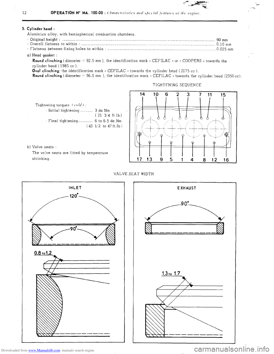
Downloaded from www.Manualslib.com manuals search engine 5. Cylinder head :
Aluminium alloy, with hemispherical combustion chambers.
- Original height : . . . . . . . . . . . . . . . . . . . . . . . . . . . . . . . . . . . . . . . . . . . . . . . . . . . . . . . . . . . . . . . . . . . . . . . . . . . . . . . . . . . . . . . . . . . . . . . . . . . . . . . . . . . . . . . . . . . . . . . . ........................ 90 mm
- Overall flatness to within : . . . . . . . . . . . . . . . . . . . . . . . . . . . . . . . . . . . . . . . . . . . . . . . . . . . . . . . . . . . . . . . . . . . . . . . . . . . . . . . . . . . . . . . . . . . . . . . . . . . . . . . . . . . . . . . . . . . . . . . . ...... 0.10 mm
- Flatness between fixing holes to within : . . . . . . . . . . . . . . . . . . . . . . . . . . . . . . . . . . . . . . . . . . . . . . . . . . . . . . . . . . . . . . . . . . . . . . . . . . . . . . . . . . . . . . . . . . . . . . . . . . . . . 0.025 mm
a) Head gasket :
Round clinching (diameter = 92.5 mm ), the identification mark (( CEFILAC 1) or (( COOPERS )) towards the
cylinder head ( 1985 cc ).
Oval clinching; the identification mark (( CEFILAC 1) towards the cylinder head (2175 cc ).
Round clinching (diameter = 96.5 mm ), the identification mark (( CEFILAC )) towards the cylinder head (2350 cc).
TIGHTFNING SEQUENCE
Tiqhtening torques f cold)
Initial tightening . . . . . . . . . . 3 da Nm
( 21 3/‘4 ft.Ib)
Final tightening . . . . . . . . . . . . . 6 to 6.5 da Nm
(43 l/2 to 47ft.Ib)
b) Valve seats :
The valve seats are fitted by temperature
shrinking.
VALVE SEAT WIDTH
INLET
I I I I I I T
17 13 9 5 1 4 8 12 16
EXHAUST
Page 66 of 394
Downloaded from www.Manualslib.com manuals search engine OPERATION No MA. 100-00 : Characteristics and special features of the engine. Op. MA. 100.00 15
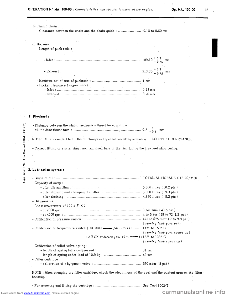
b) Timing chain :
- Clearance between the chain and the chain guide : . . . . . . . . . . . . . . . . . . . . . . . . . . 0.10 to 0.50 mm
c) Rockers :
- Length of push rods :
- Inlet : . . . . . . . . . . . . . . . . . . . . . . . . . . . . . . . . . . . . . . . . . . . . . . . . . . . . . . . . . . . . . . . . . . . . . . . . . . . . . . . . . . . . . . . . . . . . . . 189.10 ‘, Og’Q5 mm
- Exhaust : . . . . . . . . . . . . . . . . . . . . . . . . . . . . . . . . . . . . . . . . . . . . . . . . . . . . . . . . . . . . . . . . . . . . . . . . . . . . . . . . . . . . . . . 213.35 + 0.3
- 0.75 mm
- Maximum out of true of pushrods : . . . . . . . . . . . . . . . . . . . . . . . . . . . . . . . . . . . . . . . . . . . . . . . . . . . . . . . 1 mm
- Rocker clearance (engine cold) :
-Inlet : . . . . . . . . . . . . . . . . . . . . . . . . . . . . . . . . . . . . . . . . . . . . . . . . . . . . . . . . . . . . . . . . . . . . . . . . . . . . . . . . . . . . . . . . . . . . . . 0.15mm
- Exhaust : . . . . . . . . . . . . . . . . . . . . . . . . . . . . . . . . . . . . . . . . . . . . . . . . . . . . . . . . . . . . . . . . . . . . . . . . . . . . . . . . . . . . . . . . 0.20 mm
7. Flywheel :
2 - Distance between the clutch mechanism thrust face, and the 0 u clutch disc thrust face : . . . . . . . . . . . . . . . . . . . . . . . . . . . . . . . . . . . . . . . . . . . . . . . . . . . . . . . . . . . . . . . . . . . . . . . . . . . . 0.5 -is mm
7
co
G NOTE : It is essential to fit the diaphragm or flywheel mounting screws with LOCTITE FRENETANCH.
x
z - Correct fitting of starter ring : non machined face of the ring facing the flywheel shouldering.
s
2
E 8. Lubrication system :
5
z
6%
- Grade of oil . . . . . . . . . . . . . . . . . . . . . . . . . . . . . . . . . . . . . . . . . . . . . . . . . . . . . . . . . . . . . . . . . . . . . . . . . . . . . . . . . . . . . . . . . . . . . . . TOTAL ALTIGRADE GTS 20/W 50
2
- Capacity of sump :
- after dismantling : . . . . . . . .._................................................................. 5.800 litres ( IO.2 pts )
- after draining and changing the filter : : . . . . . . . . . . . . . . . l......................... 5.306 litres ( 9.3 pts )
- after draining : . . . . . . . . . . . . . . . . . . . . . . . . . . . . . . . . . . . . . . . . . . . . . . . . . . . . . . . . . . . . . . . . . . . . . . . . . . . . . . . . . . . 4.650 litres ( 8.2 pts )
- Oil pressure :
(At a temperature of 100 +‘S’ C)
- at 2000 rpm : . . . . . . . . . . . . . . . . . . . . . . . . . . . . . . . . . . . . . . . . . . . . . . . . . . . . . . . . . . . . . . . . . . . . . . . . . . . . . . . . . . . . . . . 3 .bar min. ( 43.5 psi )
- at 4000 rpm : . . . . . . . . . . . . . . . . . . . . . . . . . . . . . . . . . . . . . . . . . . . . . . . . . . . . . . . . . . . . . . . . . . . . . . . . . . . . . . . . . . . . . . 4 to 5 bar ( 58 to 72 l/2 psi )
- Calibration of pressure switch : . . . . . . . . . . . . . . . . . . . . . . . . . . . . . . . . . . . . . . . . . . . . . . . . . . . . . . . . . . . . . . . . 475 to 675 mbar ( 7 to 9.8 psi )
(warning lamp goes oat)
- Calibration of temperature switch (CX 2000 e Jan. 1975) : . . . . 1... 147’ to 150’ C
(warning lamp goes comes on)
(All CX vehicles Jan. 1975 -) : 135” to 138’ C
(warning lamp comes on )
- Calibration of relief valve spring :
- length of spring fully compressed : . . . . . . . . . . . . . . . . . . . . . . . . . . . . . . . . . . . . 31 mm
- length of spring under load of 10.9 kg : . . . . . . . . . . . . . . . . . . . . . . . . . . . . . . . . . . . . . . . . . . 42 mm
- Filter cartridge :
- calibration of (( by-pass )) valve : . . . . . . . . . . . . . . . . . . . . . . . . . . . . . . . . . . . . . . . . . . . . . . . . . . . . . . 550 mbar ( 8 psi )
NOTE : When changing the filter cartridge, check the cleanliness of the seal and’the contact area on the filter
housing.
- For removing and fitting the cartridge : . . . . . . . . . . . . . . . . . . . . . . . . . . . . . . . . . . . . . . . . . . . . . . . . . . . . Use Tool 6002-T
Page 68 of 394
Downloaded from www.Manualslib.com manuals search engine OPERATION No MA. 100-00 : Characteristics and special jeafruvs oj the cvlghv.
Op. MA. 100-00 17
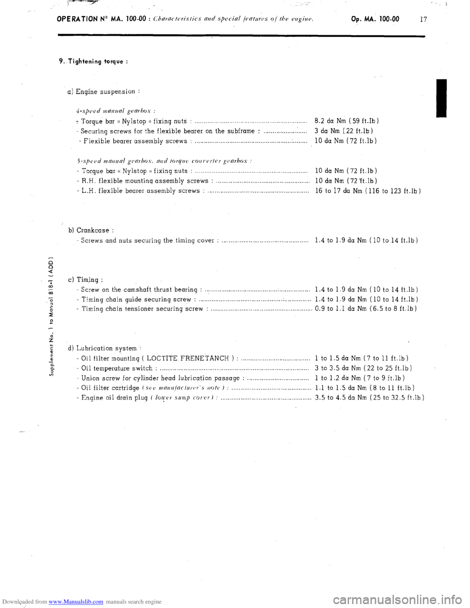
9..Tightening torque :
a) Engine suspension :
4-.spc~~d manrlal gearbox :
7 Torque bar (( Nylstop )) fixing nuts : .............................................................. 8.2 da Nm ( 59 ft.Ib )
- Securing screws for the flexible bearer on the subframe ; ........................ 3 da Nm ( 22 ft.lb)
- Flexible bearer assembly screws :
..................................................... .
........ 10 da Nm (72 ft.lb)
S-sp~~tl n1m11ra1 gca~box. and forq~~c cour,c~rtrr gc~arkos
- Torque bar (( Nylstop )) fixing nuts : . . . . . . . . . . . . . . . . . . . . . . . . . . . . . . . . . . . . . . . . . . . . . . . . . . . . . . . . . . . . . . 10 da Nm (72 ft.lb)
- R:H. flexible mountinq assembly screws : . . . . . . . . . . . . . . . . . . . . . . . . . . . . . . . . . . . . . . . . . . . . . . . . . . . . 10 da Nm ( 72 ‘ft.lb )
- L.H. flexible bearer assembly screws : . . . . . . . . . . . . . . . . . . . . . . . . . . . . . . . . . . . . . . . . . . . . . . . . . . . . . . . . 16 to 17 da Nm ( 116 to 123 ft.lb )
b) Crankcase :
Screws and nuts securing the timing cover : . . . . . . . . . . . . . . . . . . . . . . . . . . . . . . . . . . . . . . . . . . . . . . 1.4 to 1.9 da Nm (10 to 14 ft.lb)
c) Timing :
- Screw on the camshaft thrust bearing : . . . . . . . . . . . .._............................................ 1 .4 to 1 .9 da Nm ( 10 to 14 ft.lb )
- Timing chain guide securing screw : . . . . . . . . . . . ..__................................ . . . . . . . . . . . . . . .
1.4 to 1.9 da Nm ( 10 to 14 ft.lb)
- Timing chain tensioner securing screw : . . . . . . . . . . . . . . . . . . . . . . . . . . . . . . . . . . . . . . . . . . . . . . . . . . . . . . . 0.9 to 1 .I da Nm (6.5 to 8 ft.lb )
d) Lubrication system :
- Oil filter mounting ( LOCTITE FRENETANCH ) : ......................................
1 to 1 .5 da Nm ( 7 to 11 ft.lb )
- Oil temperature switch : .................................................................................. 3 to 3.5 da Nm ( 22 to 25 ft.lb )
- Union screw for cylinder head lubrication passage : ..................................
1 to 1 .2 da Nm ( 7 to 9 ft.lb )
- Oil filter cartridge ( SPV
wnrt/r]nctc/rer‘s rmte ) : ............................................ 1 .l to 1 .5 da Nm ( 8 to 11 ft.lb )
- Engine oil drain plug ( lo~!,c,r s/t~/p
co/‘cr) : .................................................. 3.5 to 4.5 da Nm (25 to 32.5 ft.lb)
Page 86 of 394
Downloaded from www.Manualslib.com manuals search engine ALL CX VEHICLES
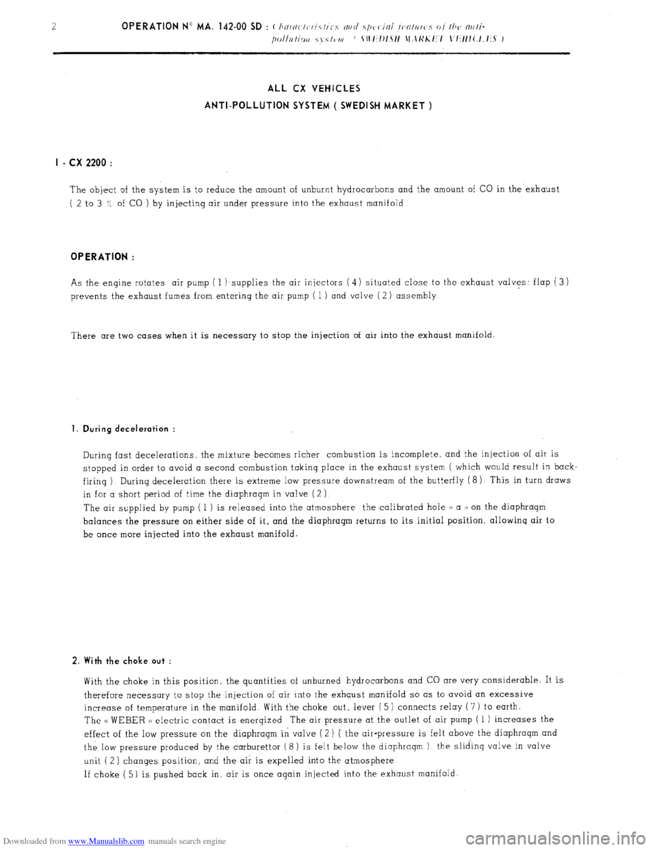
ANTI-POLLUTION SYSTEM ( SWEDISH MARKET )
I - cx 2200 :
The object of the system is to reduce the amount of unburnt hydrocarbons and the amount of CO in the exhaust
( 2 to 3 Z. of CO ) by injecting air under pressure into the exhaust manifold OPERATION :
As the engine rotates air pump ( 1 )supplies the air injectors (4) situated close to the exhaust valves: flap (3)
prevents the exhaust fumes from entering the air pump ( 1 ) and valve ( 2) assembly
There are two cases when it is necessary to stop the injection of air into the exhaust manifold. 1. During deceleration :
During fast decelerations. the mixture becomes richer combustion is incomplete, and the injection of air is
stopped in order 1.0 avoid a second combustion taking place in the exhaust system ( which would result in back
firinq ). During deceleration there is extreme low pressure downstream of the but!erfly ( 8 ). This in turn draws
in for a short period of time the diaphragm in valve (2 )
The air supplied by pump ( 1 ) is released into the atmosphere the calibrated hole u a )) on the diaphraqm
balances the pressure on either side of it, and the diaphragm returns to its initial position, allowinq air to
be once more injected into the exhaust manifold. 2. With the choke out :
With the choke in this position, the quantities of unburned hydrocarbons and CO are very considerable. It is
therefore necessary to stop the injection of air into the exhaust manifold so as to avoid an excessive
increase of temperature in the manifold. With the choke out, lever ( 5 ) connects relay ( 7 ) to earth.
The u WEBER )) electric contact is enerqized The air pressure at the outlet of air pump ( 1 ) increases the
effect of the low pressure on the diaphragm in valve (2 ) ( the air-pressure is felt above the diaphragm and
the low pressure produced by the carburettor (8) is felt below the diaphraqm ) the sliding valve in valve
unit ( 2 ) changes position, and the air is expelled into the atmosphere
If choke ( 5) is pushed back in, air is once again injected into the exhaust manifold.
Page 88 of 394
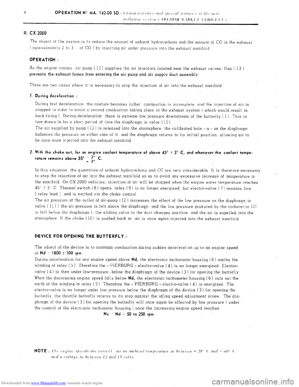
Downloaded from www.Manualslib.com manuals search engine II. cx 2000
The object of the system is t3 reduce the amount of unburnt hydrocarbons and the amount of CO in the exhaust
( approximately 2 to 3
of CO ) by injectinq air under pressure into the exhaust manifold
OPERATION :
As the enqine rotates air pump ( 12) supplies the air injectors located near the exhaust valves: flap ( 13 )
prevents the exhaust fumes from entering the air pump and air supply duct assembly.
There are two cases where it is necessary to stop the injection of air into the exhaust manifold.
1. During deceleration :
Durinq fast deceleration. the mixture becomes richer combustion is incomplete and the injection of air is
stopped in order to avoid a second combustion takinq
place in the exhaust system ( which would result in
back-firinq ) Durinq deceleration there is extreme low pressure downstream of the butterfly ( 1 ). This in
turn draws in for a short period of time the diaphragm in valve ( 11 )
The air supplied by pump ( 12 ) is released into the atmosphere, the calibrated hole (( a 1) on the diaphragm
balances the pressure on either side of it and the diaphraqm returns to its initial position, allowinq air to
be once more injected into the exhaust manifold
2. With the choke out, for an engine coolant temperature of above 45’ + 3’ C, and whenever the coolant tempe-
rature remains above 35’ i “,I C.
In this situation the quantities of unburnt hydrocarbons and CO are very considerable It ‘is therefore necessary
to stop the injection of air into the exhaust manifold so as to avoid any excessive increase of temperature in
the manifold. On CX 2000 vehicles, injkction of air will be stopped when the enqine water temperature reaches
45” + 3- C Thermal switch ( 8 ) opens, relay ( 9 )
1s no lonqer enerqized. but electro-valve ( 7 ) remains live
( relay lead ). and is earthed via the choke control
The air pressure at the outlet of air-pump ( 12 )
increases the effect of the low pressure on the diaphraqm in
valve ( 11 ) ( the air pressure is felt above the diaphraq,m, and the low pressure produced by the carburettor (2)
is felt below the diaphraqm ). the slidinq valve in the duct chanqes position and the air is expelled into the
atmogphere If the choke ( 10) is pushed back in air is once again injected into the exhaust manifold
DEVICE FOR OPENING THE BUTTERFLY :
The object of the device is to maintain combustion during sudden deceleration up to an enqine speed
of
Nd 7 1800 + 100 rpm.
Durinq deceleration for any enqine speed above Nd, the electronic tachometer housinq ( 6 ) earths the
windinq of relay ( 5) Therefore the H PIERBURG 1) electro-valve ( 4) is no lonqer enerqized. Electro-
valve ( 4) is then under low-pressure, below the diaphragm of the device ( 3 ) for opening the butterfly
When the decreasinq enqine speed falls below
Nd, the electronic tachometer housing (6 ) cuts out the
earth of the winding in relay ( 5) Therefore the (( PIERBURG )) electro-valve ( 4) is enerqized The
electro-valve is no lonqer under low pressure below the diaphraqm of the device (3) for openinq the
butterfly the throttle butterfly returns to it s stop aqainst the idlinq speed adjustment screw. The dia-
phraqm of the device (3) for openinq the butterfly will once aqain be affected by low pressure ( under
the control of the electronic tachometer housing ) once the increasing engine speed reaches
NC ~ Nd t 50 to 250 rpm
Page 89 of 394
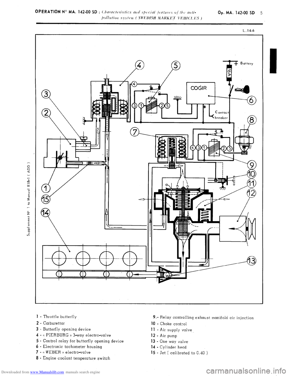
Downloaded from www.Manualslib.com manuals search engine 1 - Throttle butterfly
2 - Carburettor
3 - Butterfly openinq device 4-
N PIERBURG 1) 3-way electro-valve
5 - Control relay for butterfly opening device
6 - Electronic tachometer housing 7-
(( WEBER H electro-valve 8
- Engine coolant temperature switch 9.” Relay controlling exhaust manifold air injection 10
- Choke control
11 - Air supply valve 12
- Air pump 13 -
One way valve
14 - Cylinder head
15 - Jet ( calibrated to 0.40 )
Page 90 of 394
Downloaded from www.Manualslib.com manuals search engine OPERATION No MA. 142-O : Adj,,s/iaji f/a<, rarhnrt,//or Op. MA. 142.0
1
ADJUSTING THE IDLING SPEED
To carry out this adjustment, the following is needed
A tachometer
A device lor checkinq idling speed adjustments on the carburettor ( or on approved gas analyser )
- A CDA 23 checking oppmotus or a workshop test bench ( equipment mentioned in the Equipment and Repair
Materials list, or in the Tools and Equipment notes green notes )
NOTE : WEBER Carburettors ref. No W 54-50, 55-50, 69-50, 74-50 fitted on 1977 models onwards ore fitted with a
fool-proof plug ( white ) on the mixture screw. To adjust the exhaust emission, this plug has to be
removed, and
replaced, after adjustment, with a a Repair PI plug ( black ). See Op. MA, 142-000 for removing and fitting the plug,
and the necessary tools.
ADJUSTMENT CONDITIONS
1.
The idling speed adjus!ment must be carried out on an engine on which the rocker clearances and the ignition
are correctly set. with a clean air filter and
with the engine in good order.
2. Check that the butterflies return fully to their stops.
3. 30 not let pnythinq except the ignition and the engine cooling fan ( or ions ) impose any load on the alternator.
4. Run the engine to bring the
oil temperature up to 70 to 80’ C ( wait for the electric cooling fan ( or fans 1 to cut
in 1.
I. M 20/616, M 22/617, M 23/623 ENGINES I i< ?I< (5 wi/hr ,111 /or<,,,< co,1, <,r,cr or air ro,,di/io,ii?,g I ,I ‘-/
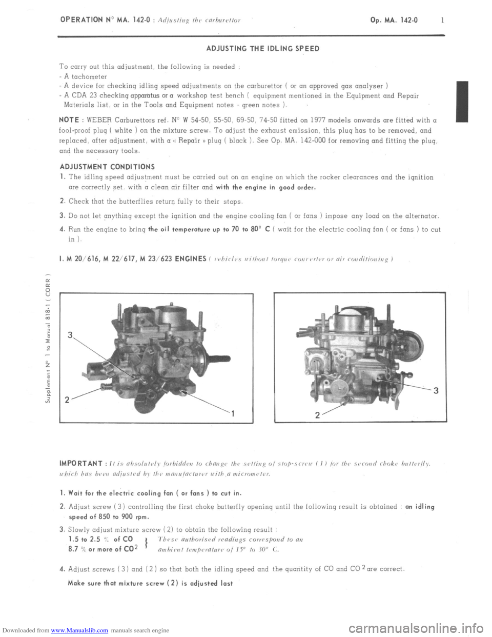
1. Wait for the electric cooling fan ( or fans ) to cut in.
2. Adjust screw (3) controlling the first choke butterfly opening until the following result is obtained : an idling
speed of 850 to 900 rpm.
3. Slowly adjust mixture screw ( 2) to obtain the following result
1.5 to 2.5 “/ of CO
1 7h~se authoris<,
8.7
% or more of CO2 nmbiot~l I~mpcuatur~ 0i 1 Y to 30” C.
4. Adjust screws (3 ) and (2 ) so that both the idling speed and the quantity of CO and CO 2 me correct.
Make sure that mixture screw (2) is adjusted last
Page 93 of 394
Downloaded from www.Manualslib.com manuals search engine 2
OPERATION No MA. 142.0 SD : (./ )I c ,,,s m,d nd;,,s/is~~ /A? Ni/li-/Joll,lli,,ill I \/i’V, b’
/ Sll l:l~/sl1 lI.\KKI:I v1:/1/c l.JT I,
CHECKING THE IDLING SPEED AND THE CO READING I (.. JXO J
On cr vehicle fitted with the following :
-distributor : DUCELLIER 4510 B
Dwell ratio 61 7: + 3 ‘Y
Dwell angle 550 + 2”
Static advance 6”
Strobe timinq
6” at 850 rpm
Centrifuqal cuwe IA 2
- carburettor : WEBER 34 DMTR 30/200 Identification mark W 63-00
spark plugs: AC 42 FS
- engine, with the following rocker clearances : Inlet = 0.15 mm, Exhaust = 0.20 mm
Checking and adjusting the CO is carried out in the following conditions
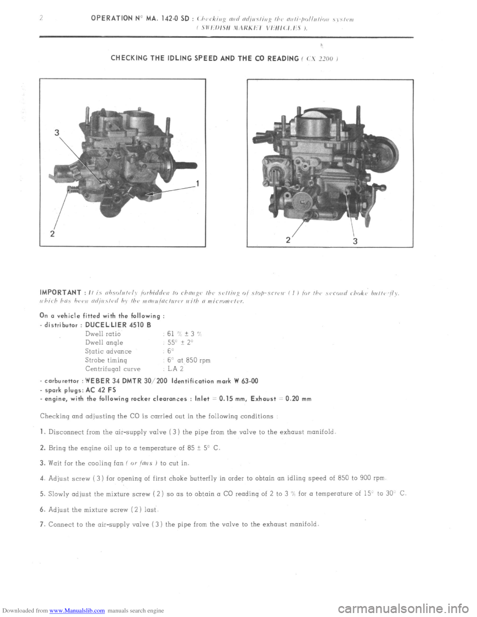
1. Disconnect from the air-supply valve ( 3) the pipe from the valve to the exhaust manifold
2. Bring the engine oil up to a temperature of 85 ? 5’ C
3. Wait for the cooling ion ( 01
ims J to cut in.
4. Adjust screw ( 3) for opening of first choke butterfly in order to obtain on idling speed of 850 to 900 rpm
5. Slowly adjust the mixture screw (2) so (IS to obtain a CO reading of 2 to 3 “L for a temperature of 15” to 30 C
6. Adjust the mixture screw (2 ) lost
7. Connect to the air-supply valve (3 ) the pipe from the valve to the exhaust manifold.