electrical Citroen CX 1985 1.G Owner's Manual
[x] Cancel search | Manufacturer: CITROEN, Model Year: 1985, Model line: CX, Model: Citroen CX 1985 1.GPages: 394
Page 320 of 394

Downloaded from www.Manualslib.com manuals search engine OPERATION N” MA. 510-00 b : A ..n A II it ~(~rttc~t7t 0 j lhv cJcctr.ical irlsldllntiari ( iront 9/
107 5 ) Op. MA. 510-00 b 9
ARRANGEMENT OF THE ELECTRICAL INSTALLATION
PRESENTATION OF THE DIAGRAMS
1. CIRCUIT DIAGRAM
a) Special feature
: The various circuits are presented in a functional way. therefore. where a unit is connected
to several circuits. its various sections are shown in cx exploded )) form on different vertical grid lines.
n
0 b) Method of identification, Identification marks are divided into three sections
<
- figures which identify components ( and not leads )
- letters LG, TB! AR. etc .~. identifying wiring harnessss,
- other letters ( Bc F. Gr, FN. Bl . . . ) identifying the colour of the extremity of the insulating sleeve.
:
r”
NOTE For the last group of identification marks. four cases may occur
marks on diagrams Bc. Bl. Ve. Gr . ..~
- No
slcc~rv ot) a lcad tbv colaur o{ which scrt‘vs as idvtltijirntiatt mark :
marks on diagrams F. Gr. F. Ve. F. Bc . . . .
- UnidetttijiGd lead : its position cannot give rise to any confusion. IMPORTANT
: Identification marks for components and wiring harnesses are arbitrary they have been chosen
for the sole purpose ‘of facilitating the use of the diagrams.
7’hr colour of tkc sl~~c~r~c~s aud tbcz IcJads arc the wly idcwtijicntiorl marks nctr,ally used ot1 the leads mak.fng
up the elcactric systc~nz 0 / th(z chicle. 2. WIRING DIAGRAM
This is a schematic diagram of the components. as they are fitted on the vehicle.
It indicates the layout of the leads, and the approximate location of the components
The method of identification is the same as for the circuit diagram.
Page 355 of 394

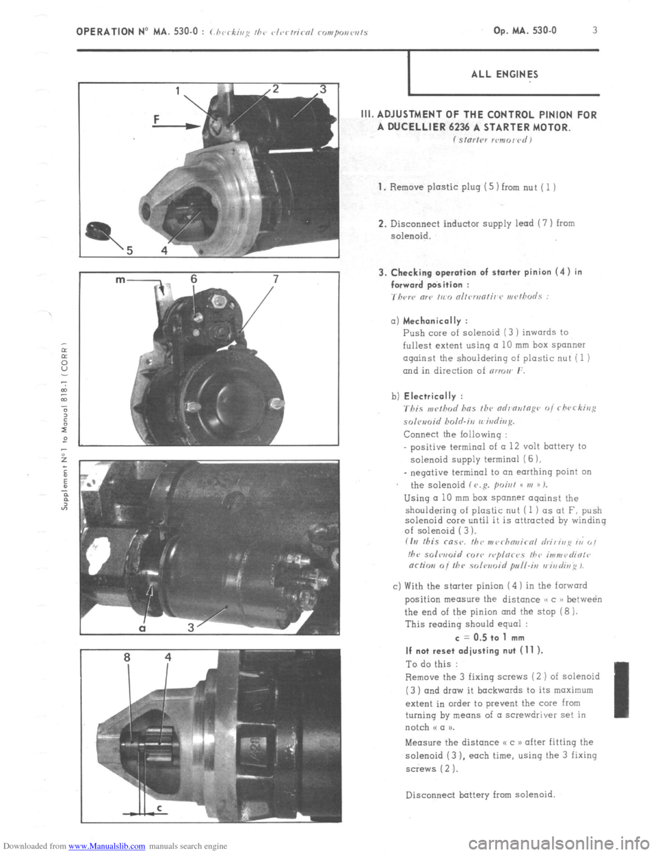
Downloaded from www.Manualslib.com manuals search engine m- 6 7 3. Checking operation of starter pinion (4) in
/ forward position :
7hcrc “lP ,,c,, nllrn,nli,~r~ rn<~~h”LS : OPERATION No MA. 530-O : (./ 1< ‘ ,,,g II,‘, vl<~rtricnl rompo,,w,ls , -k’ Op. MA. 530-O 3
ALL ENGINES
III. ADJUSTMENT OF THE CONTROL PINION FOR
A DUCELLIER 6236 A STARTER MOTOR.
f Sl”l’,Pl xmor~rdI
1.
Remove plastic plug (5) from nut ( 1 )
2. Disconnect inductor supply lead (7 ) from
solenoid. a) Mechanically :
Push core of solenoid (3 ) inwards to
fullest extent using a 10 mm box spanner
against the shouldering of plastic nut (1 )
and in direction of nrmw r.
b) Electrically :
'rbis ,w!hod has fh~ ndr'ontopr~ of rfwrking
solomid holrl.irz rrirdivg.
Connect the Iollowing :
positive terminal of (I 12 volt battery to
solenoid supply termina1 (6 ),
_ negative terminal to an earthing point on
the solenoid f V.R. poisl GC VI )) %
Using a 10 mm box spanner oqainst the
shouldering of plastic nut (1 ) as at F, push
solenoid core until it is attracted by winding
of solenoid ( 3 ).
fIrI this msr. fbc nr~~rhn~~irnl hi, irip ri 0,
!hc solwoid COY<, r<~plor<~s I/?<, i,,?“,<~diOl<~
or/ion 0i the solwoid pull-i,, vi,,di~~ 1.
c) With the starter pinion (4 ) in the forward
position measure the distance /, c )r betwe&
the end of the pinion and the stop (8 ).
This reading should equal : c = 0.5 to 1 mm
If not reset adjusting nut (11 ).
To do this :
Remove the 3 fixing saews (2 ) of solenoid
(3 ) and draw it backwards to its maximum
extent in order to prevent the core from
turning by means of a screwdriver set in
notch N a u.
Measure the distance I< c 1) after fitting the
solenoid (3 ). each time, using the 3 fixing
screws ( 2 ‘J.
Disconnect battery
from solenoid.
Page 359 of 394

Downloaded from www.Manualslib.com manuals search engine OPERATION No MA. 560.0 : ~hrrkin~ o,,d oc/@s/i,,g I/><, wiurisrrrr,, wip’r. Op. MA. 560.0
1
Fi
m
0 CHECKING AND ADJUSTING THE WINDSCREEN WIPER.
FRONT WINDSCREEN WIPER MOTOR
CHARACTERISTICS.
Manufacturer DUCELLIER
Reference No. 4966 A
Field coils Ferrite
Armature : Endfloot (adjustable by means of stop-screw) : 0.2 mm
Nominal dia. of commutator :
24 mm
Min. dia. after machining : 23 mm
Brushes : Ref. No. :
CL 7239
Minimum length after wear : 5.5 mm
Ratio : .._...................................................................................................
44 1
Connection and circuit diagram as in Op. MA. 510 00.
ELECTRICAL CHECK. BOSCH
0390 346 127
Ferrite
0
23.2 mm
23 mm
1.394.320-058 059, 062
7.5 mm
49 1
1. First speed :
Nominal power : IO watts
Speed, under no load, at 13.5 volts = 50 rpm Corresponding current = I.8 A
Torque, motor locked, at 13.5 volts = 1.9 da Nm 7 13.74 ft.lb min. Corresponding current 18 A max.
Torque at 40 rpm and 13.5 volts = 0.2 do Nm (1.45 ft.lb) Correspondinq current = 5.5 A max.
- Torque ot 20 rpm and 13.5 volts = 1.07 da Nm (7.74 ft.lb) min Corresponding current = 13.2 A max.
2. Second speed :
Nominal power : 15 watts
Speed under no load at 13.5 volts = 70 rpm Corresponding current = 2.3 A
Torque motor locked at 13.5 volts = 1.5 do Nm (IO.85 ft.lb) min Corresponding current = 21 A max
Torque at 60 rpm and 13.5 volts = 0.2 da Nm (1.45 ft.lb) min Corresponding current = 7 A max
Torque ot 30 rpm and 13.5 volts = 0.9 da Nm (6.51 ft.lb) min Corresponding current = 14.7 A mrx.
ADJUSTMENT OF WINDSCREEN WIPER ARM
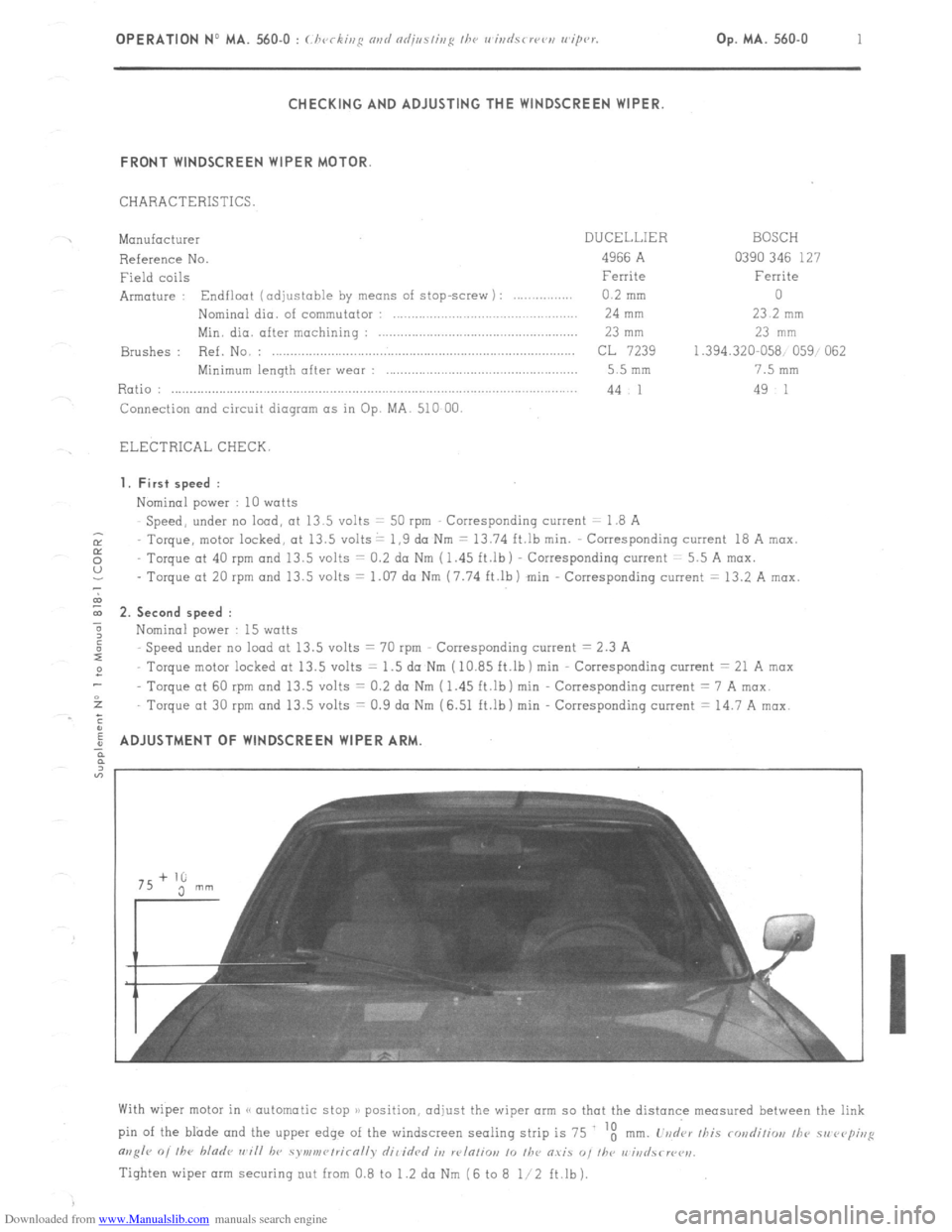
With wiper motor in (< automatic stop )/ position, adjust the wiper arm so that the distance measured between the link
pin of the blade and the upper edge of the windscreen sealing strip is 75 ‘t
mm. L’vd‘ar /his rondiliw, /he 51, rvp;,,g
m,g/r 0, /he bladr ,,~i// hv symv,r~/rirn//v dil idrd it, w/n/io,, 10 /he O.YiS “, I/w r,‘iri
Tighten wiper arm securing out from 0.8 to 1.2 da Nm (6 to 8 l/2 ft.lb).