electrical Citroen CX 1985 1.G User Guide
[x] Cancel search | Manufacturer: CITROEN, Model Year: 1985, Model line: CX, Model: Citroen CX 1985 1.GPages: 394
Page 109 of 394
Downloaded from www.Manualslib.com manuals search engine COLD START INJECTOR
When the engine is cold, fuel settles on the inlet distribution chamber, and on the cylinder walls. Therefore, the
quantity of fuel which mixes with the inlet air is smaller than in an engine which has reached normal running
temperature. The mixture thus obtained will not ignite.
The cold-start injector enriches the mixture in each inlet duct by vaporizing fuel in the inlet manifold. However,
it only comes into operation when the starter motor is actuated, and when a thermal switch located inthe engine
coolanthas simultaneously closed the circuit.
‘A helicoidal spring compresses the mobile core of,the electro-magnet and its seal fuel cannot pass through.
When the magnetic core is attracted, the injector seat is freed-off, the fuel flows past the core. and.reached the
spiral effect injector, which injects the fuel, simultaneously giving it a spiral motion, and vaporizing it very finely. ‘THERMAL SWITCH
The thermal switch cuts out the operation of the cold-start injector when the temperature of the engine reaches
ir 35” C,,For any temperature below t 35’ C, the thermal switch limits the duration of injection. The maximum
duration is approximately 7.5 sets. at - 20’ C. Duration of injection is reduced as temperature increases
The variation in duration, determined by the thermal switch,.is obtained by means of a bi-metallic strip heated
by an electrical resistance. The bi-metallic strip cuts out the circuit according to the temperature reached after
it has heated for a certain amount of time.
Page 112 of 394
Downloaded from www.Manualslib.com manuals search engine OPERATION No MA.IE. 144-00 : Chnract~~ristics o/ the H I,-jctrortic P dectrnr~ir
/i/c,1 iujcctim splcm. Op. MA.IE. 144-00 17
SUPPLEMENTARY AIR CONTROL ( 1 ) :
I’ / -...’ , _, ._,, ! .’ ! . .
At idling speed and when cold, the engine must produce more torque so as to counteract increased resistance
caused by friction. In addition to an enriched air fuel mixture, the engine also needs, when starting from cold
and during the warming-up period, to be supplied with supplementary air. The E.C.U. compensates for this
supplementary air by providing more fuel; the engine therefore has a larger amount of mixture at its disposal
to reach normal running temperature. The supplementary air control fitted in parallel with the throttle butterfly
supplies the supplementary air. The supplementary air control is heated only when the engine is running, and
its heater winding is supplied electrically as long as the ignition is switched on.
The location of the supplementary air control ‘on the engine block was selected for its good heat transfer charac-
teristics, and so as to subject the unit to the changing ambient temperature of the engine.
The opening section of the supplementary air control is automatically .adjusted according to the temperature, so
that the required idling speed is maintained regardless of engine temperature. When the latter increases, the air
channel is gradually reduced, until it is completely closed when the coolant temperature reaches approximately
+ 60” C. ->.:.. .-. : --.
,
The supplementary air control is situated at a representative spot fo.r engine running temperature. A bi-metal
spring actuates a rotary valve thereby altering the size of the air passage. Electric heating has the advantage
of allowing the. supplementary air to be adjusted at pre-set times. SWITCH ON THROTTLE BUTTERFLY SPINDLE :
,‘1 3 >_
The switch on the throttle butterfly spindle contains two contacts the idling speed contact, and the.full load contact.
The control contact, which.slides along a slot, closes the idling speed contact or the full load contact for a given
position of ‘the butterfly. The’ E.C.U. analyses the signals received so as to adjust the duration of injection.
Page 144 of 394

Downloaded from www.Manualslib.com manuals search engine ELECTRICAL CIRCUIT
-I- _ _
_ _
_ _
_ _
_
:I:
.--
-1
.-_
.-_
.-_
11 j--q
---.
---.
---.
1 r
t
Page 149 of 394
Downloaded from www.Manualslib.com manuals search engine 28 OPERATION N” MA.IE. 144-O : Ch <,c ,ng n,,d nlfjusfiup Ihe u I.-~<~tro,,ir i) <~lrr/mr,ir k’
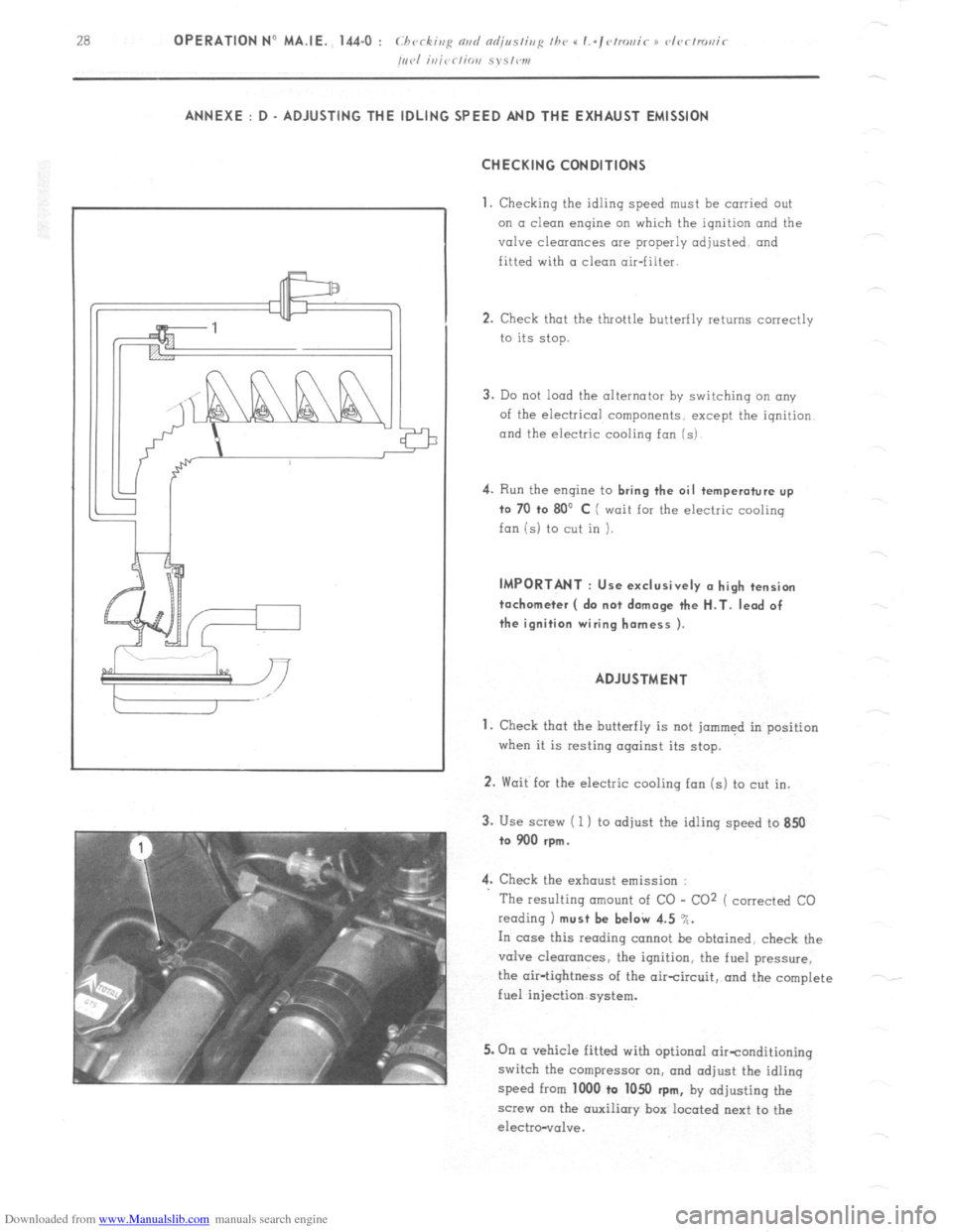
/,,,.I i,,jrr/io,, S~S,W1, ANNEXE : D - ADJUSTING THE IDLING SPEED AND THE EXHAUST EMISSION
CHECKING CONDITIONS
1.
Checking the idling speed must be carried out
on a clean engine on which the ignition and the
valve clearances are properly adjusted and
fitted with a clean air-filter.
2. Check that the throttle butterfly returns correctly
to its stop.
3. Do not load the alternator by switching an any
of the electrical components, except the iqnition
and the electric cooling fan (s) 4.
Run the engine to bring the oil temperature up
to 70 +o 80’ C ( wait for the electric cooling
fan is) to cut in ). IMPORTANT : Use exclusively (I high tension
tachometer ( do not damage the H.T. lead of
the ignition wiring harness ).
ADJUSTMENT
1. Check that the butterfly is not jammed in position
when it is resting against its stop.
2. Wait for the electric cooling fan (s) to cut in.
3. Use screw ( 1 ) to adjust the idling speed to 850
to 900 rpm.
4. Check the exhaust emission :
The resulting amount of CO - CO2 ( corrected CO
reading 1 must be beI& 4.5 %.
In case this reading cannot be obtained, check the
valve clearances, the ignition, the fuel pressure,
the air-tightness of the aircircuit, and the complete
fuel injection system.
5. On (I vehicle fitted with optional oirtonditioning
switch the compressor on, and adjust the idling
speed from 1000 to 1050
rpm, by adjusting the
screw on the auxiliary box located next to the
electro-vol”e.
Page 154 of 394

Downloaded from www.Manualslib.com manuals search engine OPERATION No MA. 210-W 0 : Ch araclcrislics ~3rd spcial /W~~NWS 0j thr d~~fmt~i~ Op. MA. 210-00 a 1
ipith syslwn.
I
M 23/622 ENGINE
TRANSISTORISED IGNITION WITH ELECTROMAGNETICALLY CREATED IMPULSES
$ OPERATING PRINCIPLE
?
:
I
,D The electronic ignition comprises a coil ( 1 1. (I transistorised module ( 2) which includes among other components.
-
.f a power transistor working as a contact breaker.
and a distributor (3 1 with a magnetic pick-up ( impulse generator )
and an H.T. rotor.
;
ii
:
F The primary current from the coil goes through a switching transistor situated in the module ( the earthing is carried
“7
out via the fixing bracket for the coil mrd module assembly ).
As an impulse is created by the sensor in the distributor. it switches off the transistor and thus cuts off the flow
of current in the coil primhry circuit. which causes a (< High Tension 1) current in the coil secondary circuit.
The module is located in the distributor..replocinq the contact breaker unit in a conventional ignition system. It
comprises a sensor (4) and a 4-point star ( 5 ).
The,sensor has a permanent moqnet inside a winding. This windinq is connected electrically to the module
I
/
The 4-point star is made of metal. and has one star per cylinder. It is fitted in place of the rotor mm cam in (I
conventional ignition system.
Page 288 of 394
Downloaded from www.Manualslib.com manuals search engine ELECTRICAL SYSTEM
M 20/616 ENGINE
PRESENTATION OF THE DIAGRAMS
1. CIRCUIT DIAGRAM
a) Special feature
: The various circuits are presented in a functional way. therefore, where a unit is connected
to several circuits, its various sections are shown in (( exploded ~‘form on different vertical grid lines. b) Method of identification
: Identification marks are divided into three sections :
- figures which identify components ( and not leads )
- letters LG. TB. AR etc... identifying wiring harnesses
_
other letters ( Bc. F, Gr, FN, Bl . . . ) identifying the colour of the extremity of the insulating sleeve.
NOTE For the Iast group of identification marks, four cases may occur
- coloiirc~rl slc,c,f,c~ 01l 0 Ic’cirf tllc, colour of wbic-h is irrc’l~~r.nrlI
marks on diagrams Bc, Bl, Ve. Gr. . . . .
= l/o s/oc,r,c, 01) 0 I~~ocl //Ic, c-olour of whit11 .ser1’c’s ns icfc~rltijicntiot, work
marks on diagram F, Gr, F. Ve, E. Bc . . . .
- colourc~ri .s/t,c~c~c, O,I n Icncl the colour uj rrhich SCJ~,‘C’.T ns ic/cvrtijitntiorL mnrk 0.5 rr~ol/ :
marks on diagram : FN -Bl, F.Ve-Bc . . . . .
-
trr/id~~~~li~~c~d I~>nd : its position cannot give rise to any confusion. .lMPORTANT
Identification marks for components and wiring harnesses are arbitrary they have been
chosen for the sole purpose of facilitating the use of the diagrams.
‘1.17~~ colour 01’ II,c~ sl~~c~~~c~s n~ld the I~~atls ore the rnr~ly id~~~~i,/t’cntiot~ vrork,s nc-/uoll\, uscjd OII tlj~~ I~~ncls
making up /h(, cllectric s~~stern c;/ the l,c~hir-Ie. 2. WIRING DIAGRAM
This is a schematic diagram of the components as they are fitted on the vehicle.
It indicates the layout of the leads, and the approximate location of the components.
The method of identification is the same as for the circuit diagram.
Page 296 of 394
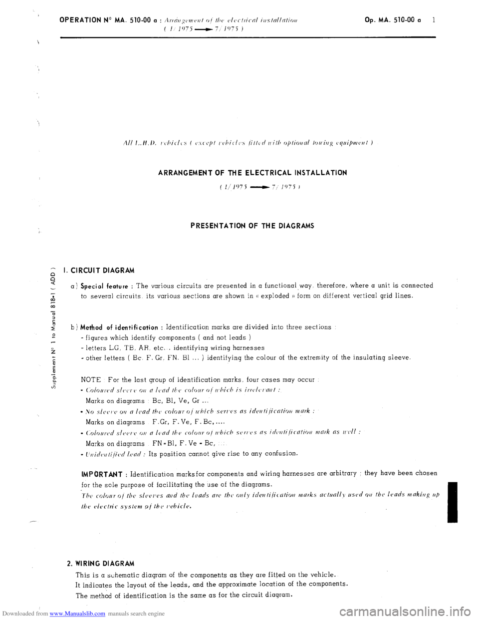
Downloaded from www.Manualslib.com manuals search engine , OPERATION No MA. 510-00 a : Arrallgc~rnc~r~t of lhe c,lc,rlric-al i~fslnllnlio~~ Op. MA. 510-00 a 1
( I 1975-
7 1075 ) ARRANGEMENT OF THE ELECTRICAL INSTALLATION
(
l/1075 - 7; 1975 I
PRESENTATION OF THE DIAGRAMS
CIRCUIT DIAGRAM
a) Special feature : The various circuits are presented in a functional way. therefore, where a unit is connected
to several circuits, its various sections are shown in u exploded )) form on different vertical grid lines.
b) Method of identification
: Identification marks are divided into three sections
- figures which identify components ( and not leads )
-letters LG. TB. AR. etc. . identifying wiring harnesses
-other letters ( Bc. F. Gr. FN. Bl . . . ) identifying the colour of the extremity of the insulating sleeve.
NOTE For the last group of identification marks, four cases may occur
- (,‘0lortrc~d slcc’r,cJ 011 cl Ic,clrl 16~~ CVlVJlr clj ri,hic-I7 is irrc~lc~l~nrll :
Marks on diagrams Bc, Bl, Ve. Gr . . .
- No s1c~~j1.v 011 a Icad the colour oj rr,hich scrr’es as
idrrt tijicnfiotl mark :
Marks on diagrams F.Gr, F. Ve, F. Bc, . . . .
s
(.~~l~~llrC~~/ s[ppr,cj o,, o /cod the rolot~r oj ~r~bich SOF,~C’S ns idcvttijic-ntiotl mark as wc~ll :
Marks on diagrams FN - Bl, F. Ve - Bc,
I
l’rlidcrllijic~rl Icarl : Its position cannot give rise to any confusion. IMPORTANT
: Identification marksfor components and wiring harnesses are arbitrary : they have been chosen
for the sole purpose of facilitating the use of the diagrams. 2. WIRING DIAGRAM
This is a schematic diagram of the components as they are fitted on the vehicle.
It indicates the layout of the leads, and the approximate location of the components.
The method of identification is the same as for the circuit diagram.
Page 304 of 394
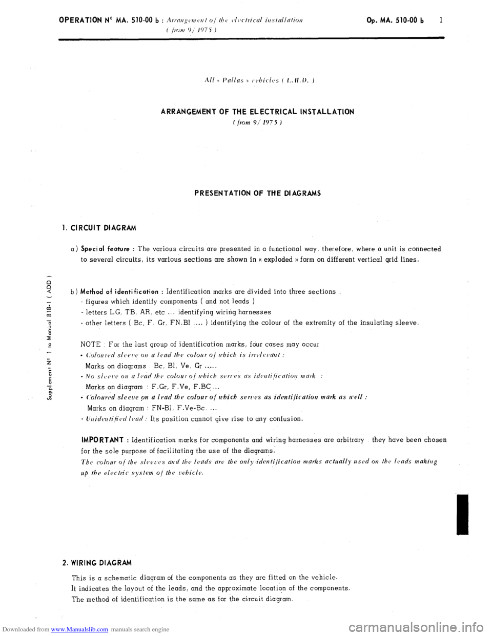
Downloaded from www.Manualslib.com manuals search engine OPERATION No MA. 510-00 b : A. ~rai~gc~mc~r~l oi t/7(’ c~lc~ctrical itfstallation
i I,07jf 9, 1975 J Op. MA. 510-00 b 1
ARRANGEMENT OF THE ELECTRICAL INSTALLATION
f from 9i 197 5 ) PRESENTATION OF THE DIAGRAMS
1, CIRCUIT DIAGRAM
a) Special feature : The various circuits are presented in a functional way, therefore, where a unit is connected
to several circuits, its various sections are shown in CC exploded )) form on different vertical grid lines. i
b) Method of identification : Identification marks are divided into three sections
‘; - figures which identify components ( and not leads )
co
co - letters LG. TB. AR. etc .“. identifying wiring harnesses
0
.3 - other letters ( Bc: F Gr, FN.Bl .-.. ) identifying the colour of the extremity of the insulating sleeve.
c
r”
e NOTE For the last group of identification marks, four cases may occur
2
l C0lo~red slcrrv on a lead the colour oj r&i& is irrvler~a~~t :
Marks on diagrams Bc, Bl. Ve. Gr . . . .
c
i - NO slc~er,c 011 a ledd the colour of rr~hich .ser~‘es as ideutijicatiotl mark. :
2 Marks on diagram : F.Gr, F.Ve, F.BG . . .
l2 c
Coloured sleeve pn a lead the colour o/ which serr1c.s as identification mark as well :
Marks on diagram : FN-Bl. F.Ve-Bc. . . .
- Urlidcntijied lead : Its position cannot give rise to any confusion. IMPORTANT
: Identification marks for components and wiring harnesses are arbitrary they have been chosen
for the sole purpose of facilitating the use of the diagrams.
The colour of the sl~~e~-cs arld the leads are the only.identijication marks actually used ow the leads making
up the electric system oj the r;ehic!e. 2. WIRING DIAGRAM
This is a schematic diagram of the components as they are fitted on the vehicle.
It indicates the layout of the leads, and the approximate location of the components.
The method of identification is the same as for the circuit diagram.
Page 305 of 394
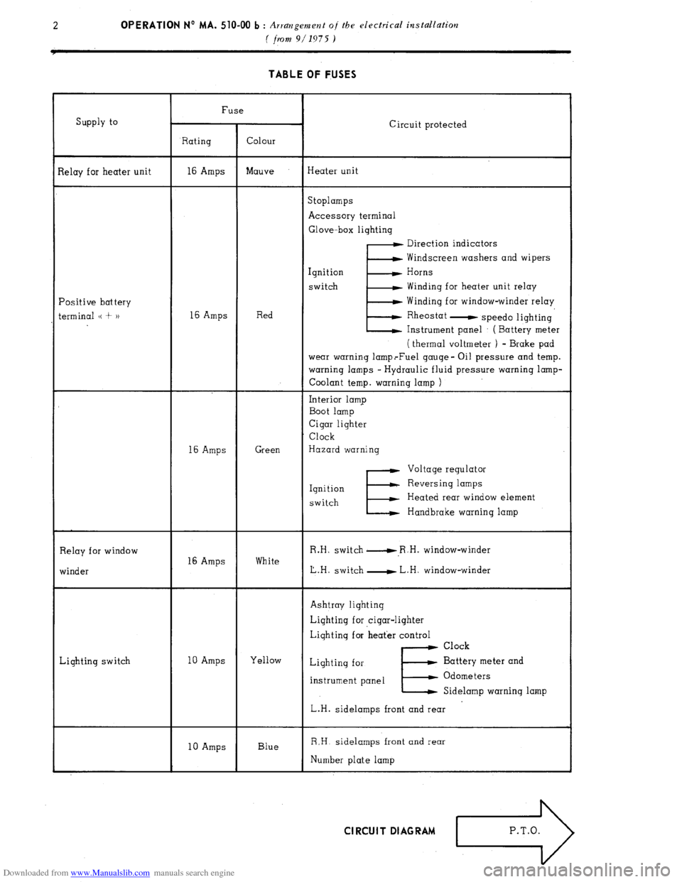
Downloaded from www.Manualslib.com manuals search engine 2 OPERATION No MA. 510-00 b : Arratzgement of the electrical installation
( jhrl 9/1975 ) TABLE OF FUSES
Supply to
lelay for heater unit
‘ositive battery
erminal (( + 1) Fuse
Circuit protected
Rating Colour
16 Amps Mauve Heater unit
Stoplamps
Accessory terminal
Glove-box lighting
E Direction indicators
Windscreen washers and wipers
Ignition Horns
switch Winding for heater unit relay
Winding for window-winder relay
16 Amps Red Rheostat
- speed0 lighting
Instrument panel : ( Battery meter
( thermal voltmeter ) - Brake pad
wear warning lamp.-Fuel gauge- Oil pressure and temp.
warning lamps - Hydraulic fluid pressure warning lamp-
Coolant temp. warning lamp )
Interior lamp
Boot lamp
Cigar lighter
Clock
16 Amps Green Hazard warning
E Voltage regulator
Ignition Reversing lamps
switch Heated rear window element
Handbrake warning lamp
Relay for window
winder 16 Amps White R.H. switch u,R.H. window-winder
L.H. switch - L.H. window-winder
Lighting switch Ashtray lighting
Lighting for cigar-lighter
Lighting for heat’er control
Clock
10 Amps Yellow
Lighting for Battery meter and
instrument panel
E. Odometers
Sidelamp warning lamp
L.H. sidelamps front and rear
10 Amps Blue R,H. sidelamps front and rear
Number plate lamp Cl RCU I T DI AG RAM
Page 312 of 394
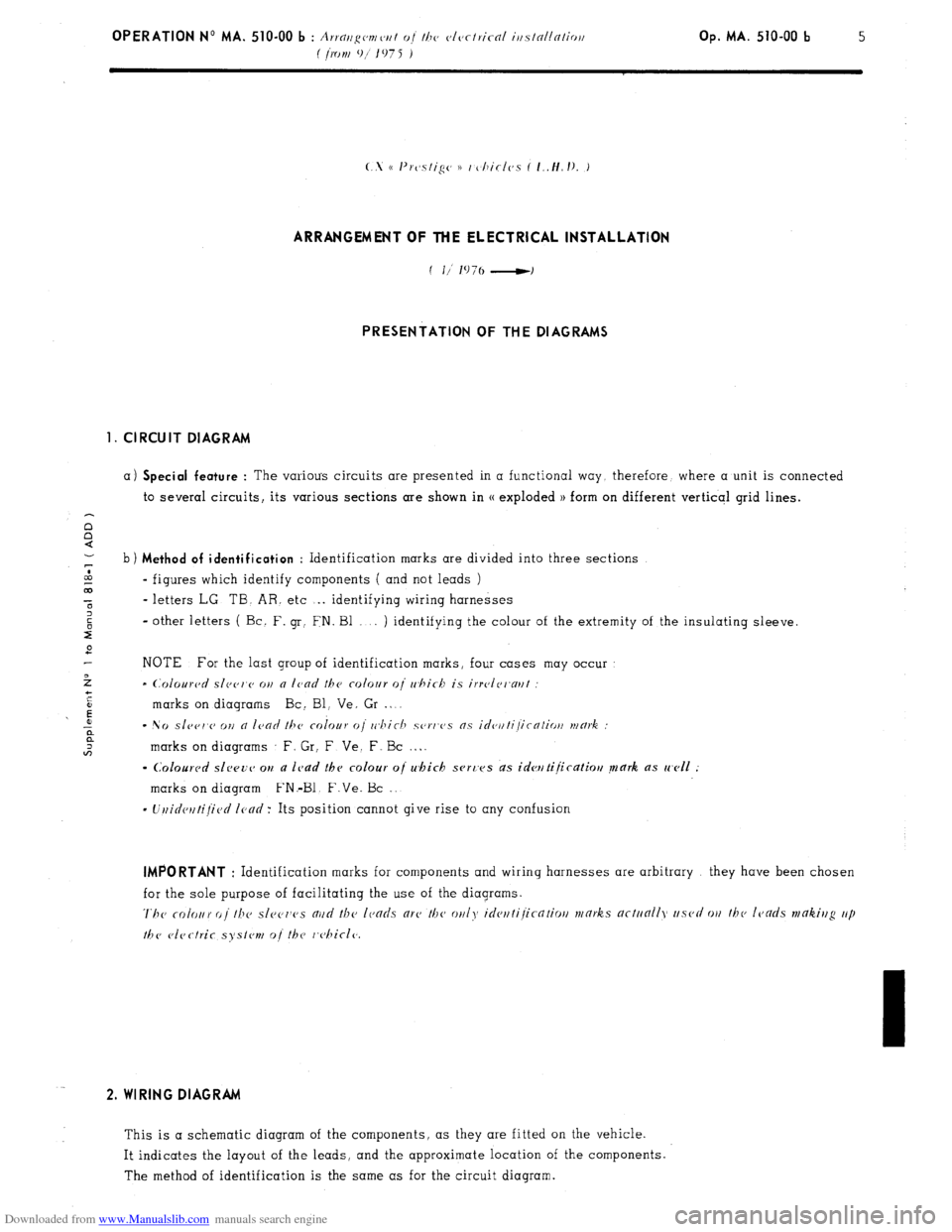
Downloaded from www.Manualslib.com manuals search engine Op. MA. 510-00 b 5
ARRANGEMENT OF THE ELECTRICAL INSTALLATION
PRESENTATION OF THE DIAGRAMS
1. CIRCUIT DIAGRAM
a) Special feature : The various circuits are presented in a functional way. therefore, where a unit is connected
to several circuits, its various sections are shown in (( exploded 1) form on different verticql grid lines.
b) Method of identification
: Identification marks are divided into three sections
CA
- figures which identify components ( and not leads )
00
t - letters LG. TB. AR. etc . . identifying wiring harnesses
2
2 - other letters ( Bc. F. gr: FN. Bl . . ) identifying the colour of the extremity of the insulating sleeve.
2
NOTE For the last group of identification marks, four cases may occur
>
- (~~olourc~d slec~r~c~ on a lcad the colour 0i whirb is irrvlri~aul
+
i
t
’ E marks on diagrams Bc: Bl, Ve, Gr . L
r: - No sle~r,c> OII n ICOO ~hc colour (Ii rr~hic-h sorws ns idc~~lti/icntio~/ mmk :
;: marks on diagrams F. Gr, F Ve. F. Bc . . .
- Colourc~d slwv~~ ou a lc,ad thv colour oj which svrc’es ds idwtijicatiou mark as well :
marks on diagram FN.-Bl. F.Ve. Bc ,.
- Uuidctltijied Icncl: Its position cannot give rise to any confusion IMPORTANT
: Identification marks for components and wiring harnesses are arbitrary they have been chosen
for the sole purpose of facilitating the use of the diagrams.
The rofour oi the sl~~c~ws nud the lends arc’ the on/?, ideuti/icntio// works actunlly used WI thv leads mtikiug up
the vlectrir syslvn, o/ the r,c,hicl(~. 2. WIRING DIAGRAM
This is a schematic diagram of the components, as they are fitted on the vehicle.
It indicates the layout of the leads, and the approximate location of the components.
The method of identification is the same as for the circuit diagram.