engine CITROEN CX 1988 User Guide
[x] Cancel search | Manufacturer: CITROEN, Model Year: 1988, Model line: CX, Model: CITROEN CX 1988Pages: 648, PDF Size: 95.8 MB
Page 107 of 648
Toothed sector for locking the engine flywheel REMOVING/REFITTING THE TIMING
BUT, ON THE VEHICLE
---____ .-
Page 108 of 648
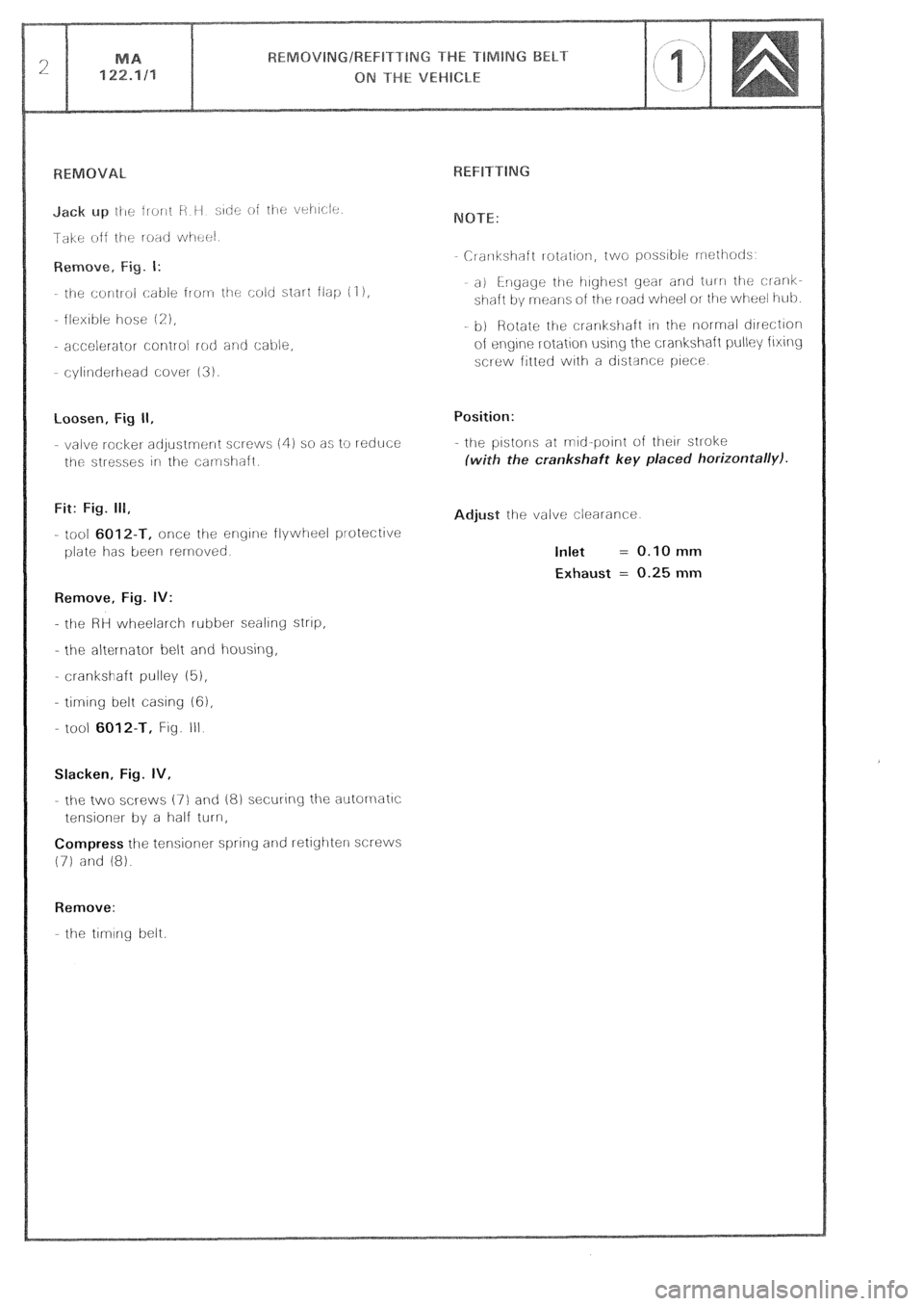
loosen, Fig II,
- valve rocket adjustrnr:nt screws (4) so as to reduce
the stresses irl the camshaft.
Fit: Fig. 111,
- tool 6012-T, once the engine flywheel protective
plate has been rernoved
Remove, Fig. IV:
- the HH wheelarch rubber sealing strtp,
- the al&l-nator belt and housing,
- crankshaft pulley (5),
- timing belt casing 161,
- tool
6012-T, Fig. III
Slacken, Fig. IV,
- the two XI-ews (7) and 18) securing the autornatlc
tensioner by a half turn,
Compress the tensioner spring and retighterl screws
(71 and 18).
Remove:
the timing belt. Crarlkshaft rotation, two pnss~ble rrrothotls
a) i-rlgage the irighest gear and tul n the clank-
shaft by means oi the road wheel OI the wheel i-tub
b) Rotate ti-le crankstlaft 1i1 the normal direction
of eqne rotation using the crankshaft pulley fixing
screw fitted with a ciistsnce piece
Position:
- the pistons at mid-point of their stroke
ith the crankshaft key placed horizontally).
djust the valve clearance
Inlet = 0.10 mm
Exhaust = 0.25 mm
Page 111 of 648
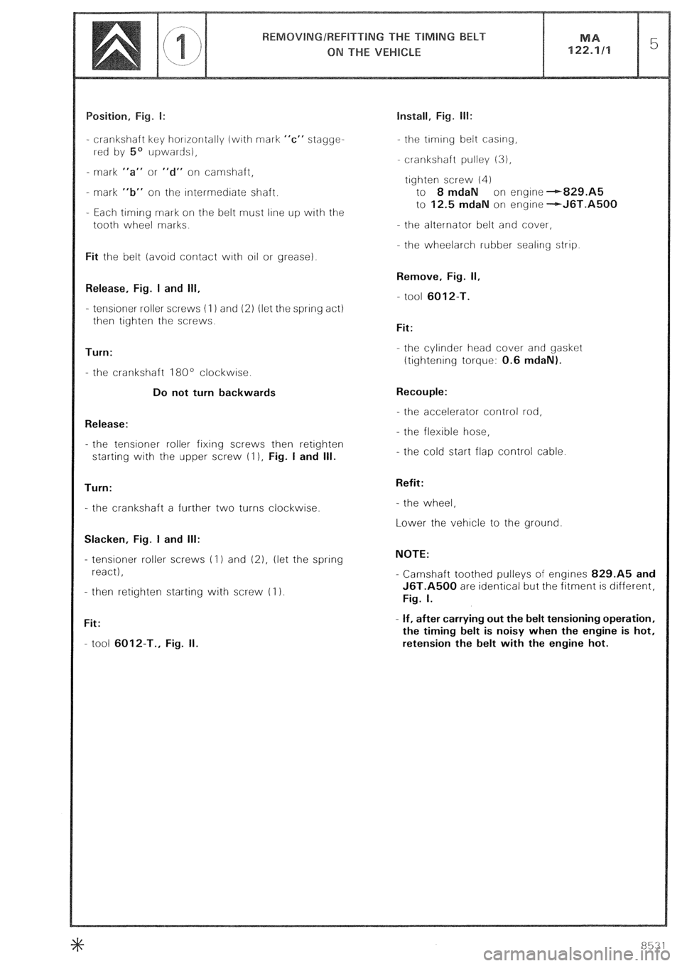
- crankshaft key horrrontally (with mark “c” stagge-
rred by 5’ upwards),
- mark “a” or “d” on camshaft,
- mark “b” on the rntermedrate shaft.
- Each timing mark on the belt must line up with the
tooth wheel marks.
Fit the belt (avoid contact with oil or grease).
Release, Fig. I and 111,
- tensioner roller screws (I 1 and 12) (let the spring act)
then tighten the screws.
Turn:
- the crankshaft 180’ clockwise.
Do not turn backwards
Release:
- the tensioner roller fixing screws then retrghten
starting with the upper screw (I ), Fig. I and Ill.
Turn:
- the crankshaft a further two turns clockwise.
Slacken, Fig. I and Ill:
- tensioner roller screws (1) and (21, (let the spring
react),
- then retighten starting with screw (I 1.
Fit:
- tool 6012-T., Fig. II. Install, Fig. lb:
the trming belt casing,
crankshaft pulley 13),
trghten screw (4)
to 8 mdaN on engine --r-829.A5
to 12.5 mdaN on engrne -+J6T.A5QQ
- the alternator belt and cover,
- the wheelarch rubber sealing strip.
Remove, Fig. II,
- tool 6012-T.
Fit:
- the cylinder head cover and gasket
ttightenrng torque: 0.6 mdaN).
Recouple:
- the accelerator control rod,
- the flexible hose,
- the cold start flap control cable.
Refit:
- the wheel,
Lower the vehicle to the ground.
NOTE:
- Camshaft toothed pulleys of engines 829.A5 and
J6T.A500 are identical but the fitment is different,
Fig. I.
- If, after carrying out the belt tensioning operation,
the timing belt is noisy when the engine is hot,
retension the belt with the engine hot.
Page 116 of 648

emove:
the I-oati Wi-l~~d,
- the wheelarch lrnrrng,
- the belt protectron covets
Position: Fig. I and II
the valves of cylrnder No. 1 rn the “rocking” ~OSI-
tion (look Into the engine 011 filler),
the flywheel wrth mar-ks- -alrgned,
- camsfraft gear wheel mark A opposite screw 12)
Loosen:
the nuts of the tensioners and compress the spring
of eacir tensloner. Hetighten the nuts.
Remove:
- injection pump belt,
- the trmrng belt
REFITTING
Fit, Fig. II:
the timrng belt- marks t-+-) and i-e-1 on the belt
should face the marks A and B on pinrons (there
are 35 pitches between A and B, passing around
the tensloner roller (I 1).
Loosen the nuts of the tensioner roller.
Install, Fig. III:
- tool 6Q28-T.K. on the roller
- the tool weight over the mark 2 of the rod, Fig 1V. Fitting the injection pump belt:
Run the engrne by 1 turn err the drrectrorr of rotation
until marks--- +- /Ino up, Fig. I
(wrth cylinder No 1 at the rnrtral trmrng
point)
Setting the pump to the injection point:
refer to Op @ MA. 146-011
Fit the InJectron purnf, drrvrng belt with the srde oppo-
site the roller, trght.
Slacken the roller nut. Let the roller- spring react
Tighten the rnut to 2 mdaN.
Rotate the engine by 2 turns in the direction of nor-
rnal rotation and check the pump timrng.
Remove the tools
Start the engine Warrn it up until the electric cooling
fans operate.
Retension the belt while the engine is hot, Fig. IV
Refit:
- the protectron covers,
- the wheelarch lining,
the road wheel
Page 119 of 648
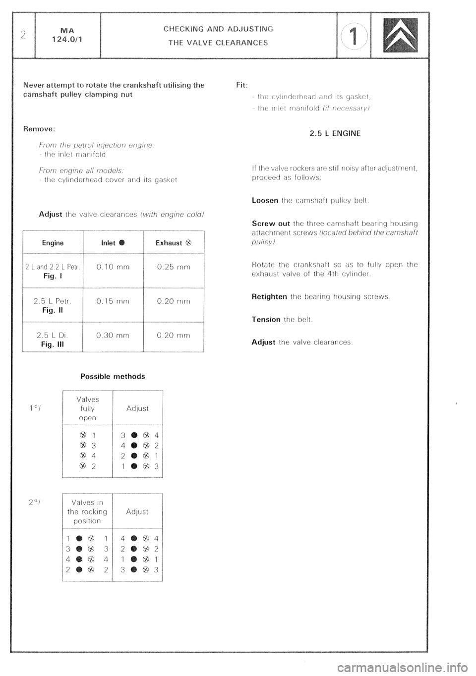
Engine Inlet Exhaust @
2 I. did 2 2 L Pet1
Fig. I
0 IO rnrr 0.25 rrirr
2.5 l- Petr.
Fig. II
0.15 mm 0.20 mm
Possible methods
1 “I
%“I
Valves
fully
open
64 1
@3
ciD4
69%
Adjust
3 694
4 692
2
@ 1
1 ‘83
Valves in
the r-ocklng
position Adjust If the valve rockers arc? sl~l! noIs\; after adystment,
proceec as follows
Screw out lhe three carmshaft bearing houslng
attachment screws iiocared beii/no’ rhe
carnshfl
pu//e)/i
Retighten
the beal-ing housing screws
Tension the belt.
Adjust the valve clearances.
Page 122 of 648
CHECKING AND ADJUSTING
THE ENGINE SUPPORT BRACKETS
-.~ ~.~ -.-... --- >
Page 132 of 648
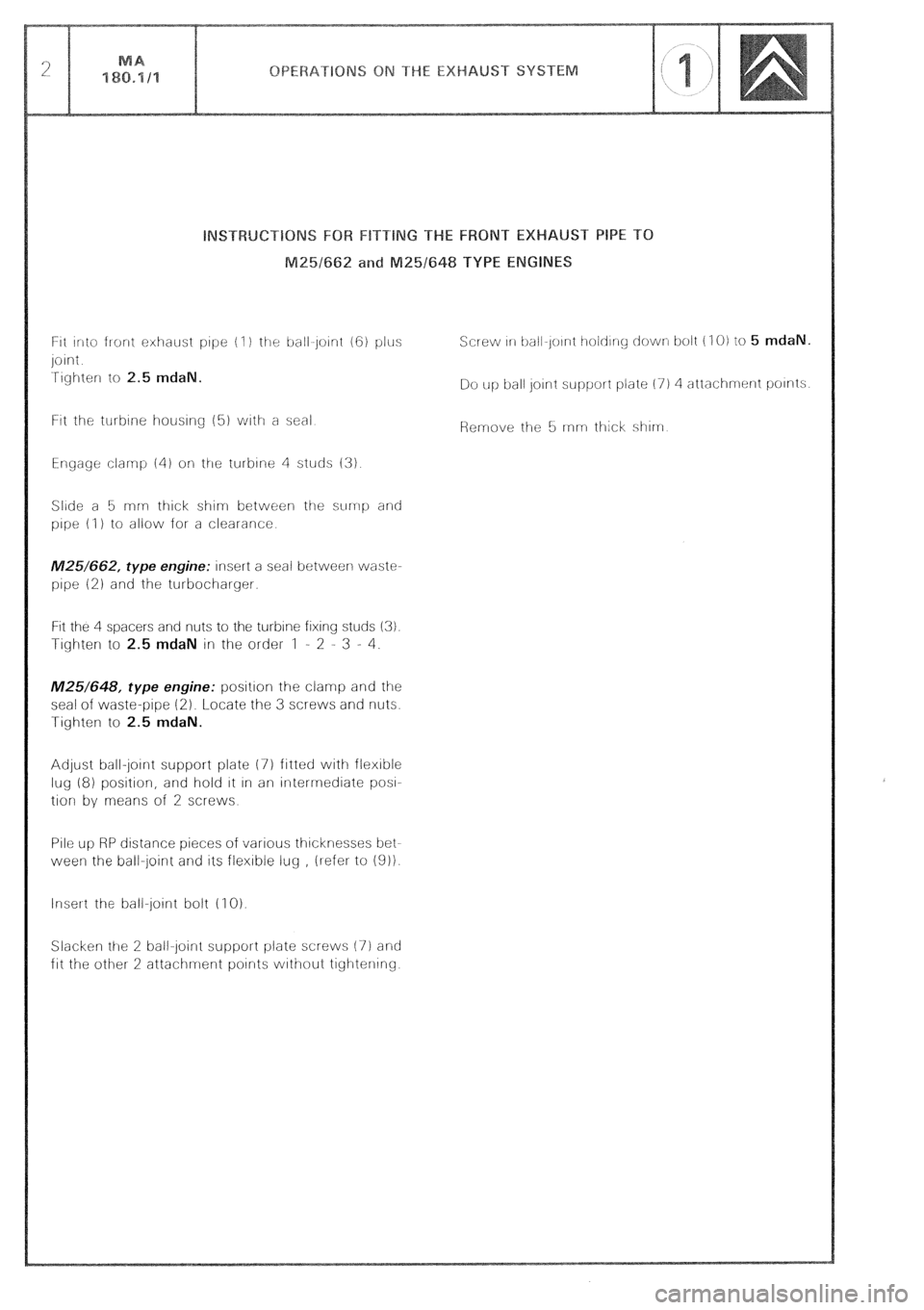
ht into front exhaust pope (I ) the ball~joint (6) plus
joint
Tighter to 2.5 mdaN.
Ftt the turbine housing (51 vuith a seal
Engage clamp 141 oli the turbine 4 studs (3)
Slide a 5 rnn- thick shim between the sump and
pipe (I ) to allow for a clearance
M25/662, type engine: insert a seal between waste-
pipe 12) and the turbocharger.
Fit the 4 spacers and nuts to the turbine fixing studs (3).
Tighter to 2.5 mdaN in the order 1 - 2 - 3 - 4.
M25/648, type engine: position the clamp and the
seal of waste-pipe (2). Locate the 3 screws and nuts.
Tighten to 2.5 mdaN.
Adjust ball-jotnt support plate 17) fitted with flexible
lug (8) position, and hold It In an intermediate
pow
tion by means of 2 screws
Pile up RP distance pieces of various thicknesses bet-
ween the ball-joint and its flexible lug , ilefer to 1911.
Insert the ball-joint bolt (1 0).
Slacker ttre 2 ball-joint support plate screws (7) and
fit the other 2 attachment points without tightening Screw 111 ball-Joirnt t~old~ny down bolt (I 0) to 5 mdaN.
Do up ball Joint support plate (7) 4 attachment points
Page 147 of 648
- Remove the ileader tank cap
Refit the cap
Run
the engine at 2000 rprrl approx , until the cooling fan(s) has (have) cut In
NEVER OPEN THE CAP OF THE HEA
OPERATING. THE ELECTRIC COOLING FAN(S) IS (ARE)
Top up
the coolant tevel in the header tank
Page 157 of 648
GENERAL FEATURES OF THE CARBURATION
FITTING. Fig. I:
5. FIN the tamper-proof protective plug (a):
- load gun A,
- screw tool E onto gun A,
- position plug (a) in its housing on the carburettor (make sure it is fitted the right way round Fig. 111,
- actuate the gun until the plug is properly located.
EXHAUST EMISSION CONTROL
In order to comply with current regulations, the checking and adjustment of the exhaust emission from vehicles
with a petrol engine must, without fail, be performed after the following operations:
I. ENGINE REPLACEMENT.
II. CARBURETTOR REPLACEMENT.
Ill. WORK ON THE CARBURETTOR.
Replacement of parts of the carburettor.
Carburettor adjustment.
Work on the carburettor controls.
IV. WORK ON THE INLET MANIFOLD.
Replacement or removal of:
- the inlet manifold,
- the air filter,
- crankcase gas recirculation system
V. WORK ON THE ENGINE.
Rocker adjustment.
Replacement or removal of:
- the cylinder head,
- the camshaft,
- the rockers,
- the valves,
- the liners and pistons.
VI. WORK ON THE IGNITION.
Replacement or reconditioning of the distributor (wholly or partially)
Adjustment or replacement of the sparking plugs.
Adjustment of the ignition timing.
VII. WORK ON EXHAUST SYSTEM.
Replacement or removal of:
- the exhaust manifold,
- the silencer or any part of the exhaust.
VIII. WORK ON THE EMISSION CONTROL SYSTEM.
When the vehicle is fitted with a specific equipment (e.g. on vehicles of SWEDEN, AUSTRALlA or JAPAN type)
Page 160 of 648
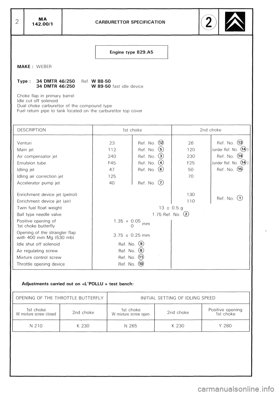
CARBURETTOR SPECIFICATION
Engine type 829.A5
t
MAKE : WEBER
Type : 34 DMTR 461250 Ref. W 88-50
34 DMTR 46/250 W 89-50 fast idle device
Choke flap in primary barrel
Idle cut off solenoid
Dual choke carburettor of the compound type
Fuel return pipe to tank located on the carburettor top cover
DESCRIPTION 1st choke 2nd choke
Venturi
23 Ref. No. @ 26 Ref. No. @
Main jet 112 Ref. No. @ 120 (under Ref No. @)
Air compensator jet
240 Ref. No. @ 230 Ref. No. @
Emulsion tube F45 Ref. No. @ F25 (under Ref. No. @)
Idling jet 47 Ref. No. @ 50 Ref. No. @
Idling air correction jet
125 70
Accelerator pump jet 40 Ref. No. @
Enrichment device jet (petrol) 130
Enrichment device jet (air) 110 Ref. No. @
Twin fuel float weight 13 -t 0.5 g
Ball type needle valve 1.75 Ref. No. @
Positive opening of 1.35 + 0.05 mm
1st choke butterfly 0
Opening of the strangler flap
with 400 mm Mg (530 nib) 3.75 f 0.25 mm
Idle shut off solenoid Ref. No. @
Air regulating screw Ref. No. @
Mixture control screw Ref. No. @
Throttle opening device Ref. No. @
Adjustments carried out on CCL’POLLU v test bench:
OPENING OF THE THROTTLE BUTTERFLY INITIAL SETTING OF IDLING SPEED
1st choke
2nd choke 1st choke Positive opening
W mrxture screw closed W mixture screw open 2nd choke
1st choke
N 210 K 230 N 265 K 230 Y 280